INFINITI QX4 2001 Factory Service Manual
QX4 2001
INFINITI
INFINITI
https://www.carmanualsonline.info/img/42/57027/w960_57027-0.png
INFINITI QX4 2001 Factory Service Manual
Page 286 of 2395
ComponentsNBAT0108
SAT147JA
GI
MA
EM
LC
EC
FE
TF
PD
AX
SU
BR
ST
RS
BT
HA
SC
EL
IDX
OVERHAUL
Components
AT-281
Page 288 of 2395
SAT155K
GI
MA
EM
LC
EC
FE
TF
PD
AX
SU
BR
ST
RS
BT
HA
SC
EL
IDX
OVERHAUL
Components (Cont'd)
AT-283
Page 290 of 2395
Locations of Needle Bearings, Thrust Washers
and Snap Rings
NBAT0110
SAT140JB
GI
MA
EM
LC
EC
FE
TF
PD
AX
SU
BR
ST
RS
BT
HA
SC
EL
IDX
OVERHAUL
Locations of Needle Bearings, Thrust Washers and Snap Rings
AT-285
Page 292 of 2395

SAT171B
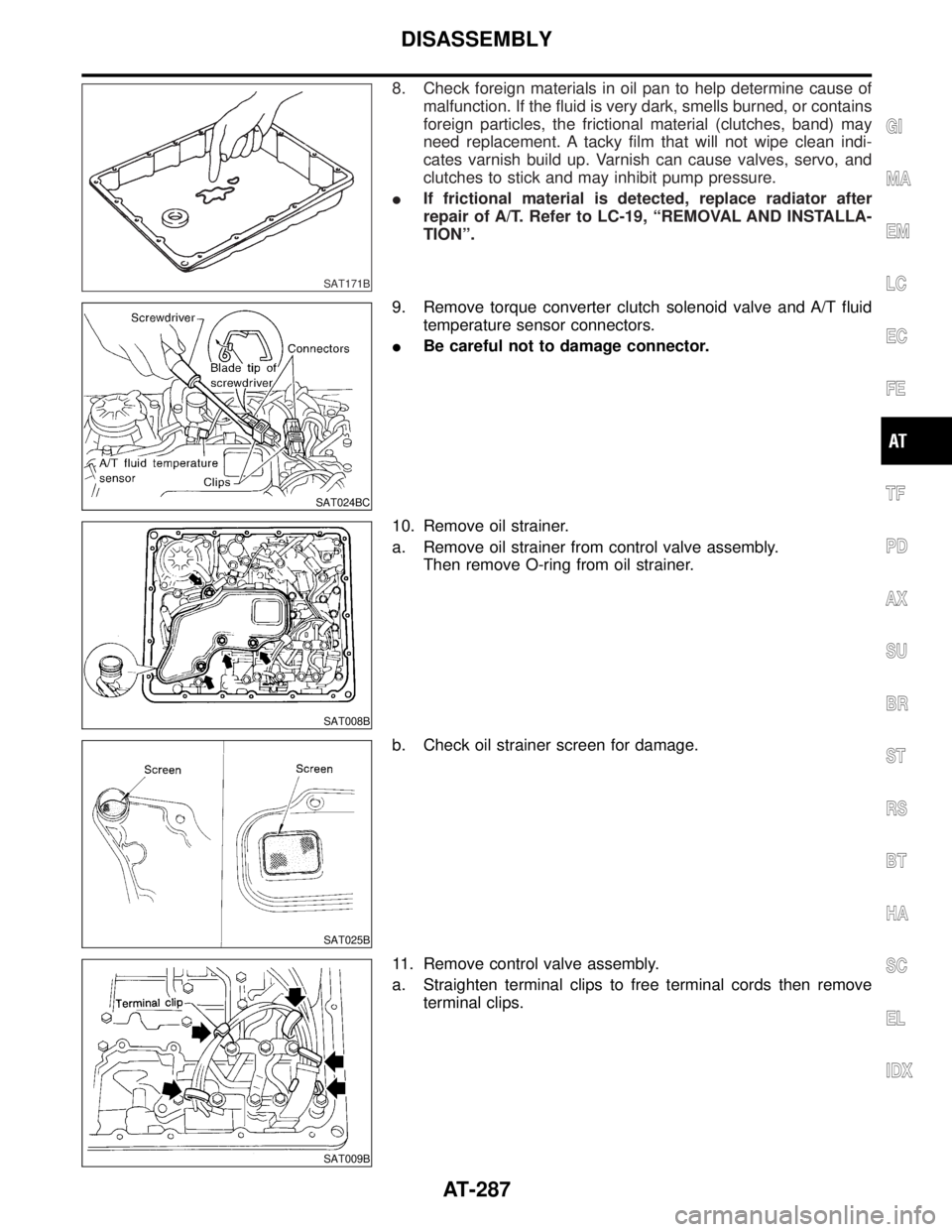
8. Check foreign materials in oil pan to help determine cause of
malfunction. If the fluid is very dark, smells burned, or contains
foreign particles, the frictional material (clutches, band) may
need replacement. A tacky film that will not wipe clean indi-
cates varnish build up. Varnish can cause valves, servo, and
clutches to stick and may inhibit pump pressure.
IIf frictional material is detected, replace radiator after
repair of A/T. Refer to LC-19, ªREMOVAL AND INSTALLA-
TIONº.
SAT024BC
9. Remove torque converter clutch solenoid valve and A/T fluid
temperature sensor connectors.
IBe careful not to damage connector.
SAT008B
10. Remove oil strainer.
a. Remove oil strainer from control valve assembly.
Then remove O-ring from oil strainer.
SAT025B
b. Check oil strainer screen for damage.
SAT009B
11. Remove control valve assembly.
a. Straighten terminal clips to free terminal cords then remove
terminal clips.
GI
MA
EM
LC
EC
FE
TF
PD
AX
SU
BR
ST
RS
BT
HA
SC
EL
IDX
DISASSEMBLY
AT-287
Page 294 of 2395
SAT999A
13. Remove converter housing from transmission case.
IBe careful not to scratch converter housing.
SAT995A
14. Remove O-ring from input shaft.
SAT027B
15. Remove oil pump assembly.
a. Attach Tool to oil pump assembly and extract it evenly from
transmission case.
SAT028B
b. Remove O-ring from oil pump assembly.
c. Remove traces of sealant from oil pump housing.
IBe careful not to scratch pump housing.
SAT108B
d. Remove needle bearing and thrust washer from oil pump
assembly.
GI
MA
EM
LC
EC
FE
TF
PD
AX
SU
BR
ST
RS
BT
HA
SC
EL
IDX
DISASSEMBLY
AT-289
Page 296 of 2395
SAT113B
b. Remove front bearing race from clutch pack.
c. Remove rear bearing race from clutch pack.
SAT031B
d. Remove front planetary carrier from transmission case.
SAT968A
e. Remove front needle bearing from front planetary carrier.
f. Remove rear bearing from front planetary carrier.
SAT974A
g. Remove rear sun gear from transmission case.
SAT546J
19. Remove rear extension assembly (2WD model only).
a. Remove rear extension assembly.
b. Remove parking gear and needle bearing.
CAUTION:
Insert your hand between rear extension and transmission
case. Detach rear extension assembly while holding parking
gear and needle bearing by hand.
c. Remove rear extension gasket.
GI
MA
EM
LC
EC
FE
TF
PD
AX
SU
BR
ST
RS
BT
HA
SC
EL
IDX
DISASSEMBLY
AT-291
Page 298 of 2395
SAT109B
d. Remove output shaft and parking gear as a unit from transmis-
sion case.
e. Remove parking gear from output shaft.
SAT033B
f. Remove needle bearing from transmission case.
SAT954A
23. Remove rear side clutch and gear components.
a. Remove front internal gear.
SAT110B
b. Remove bearing race from front internal gear.
SAT111B
c. Remove needle bearing from rear internal gear.
GI
MA
EM
LC
EC
FE
TF
PD
AX
SU
BR
ST
RS
BT
HA
SC
EL
IDX
DISASSEMBLY
AT-293
Page 300 of 2395
SAT039B
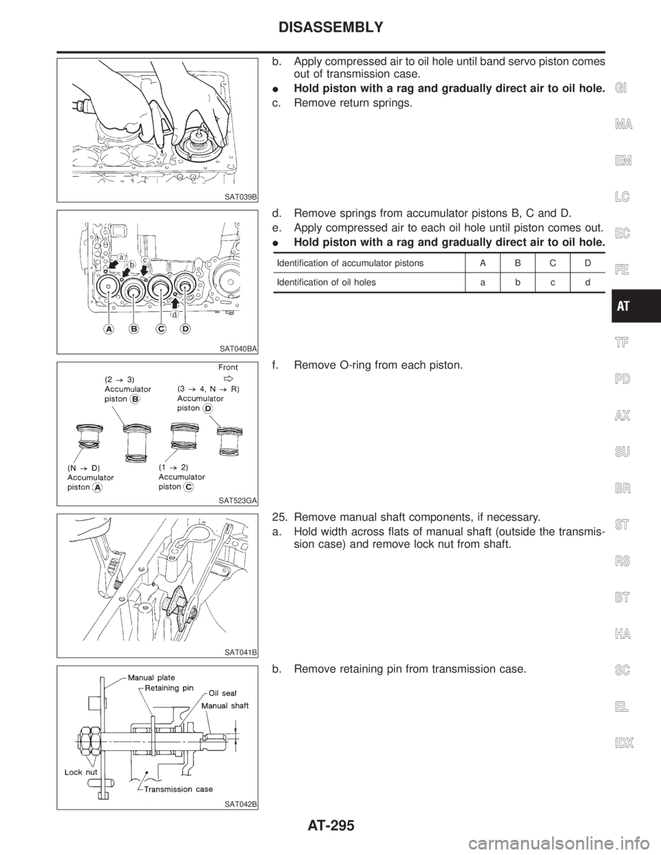
b. Apply compressed air to oil hole until band servo piston comes
out of transmission case.
IHold piston with a rag and gradually direct air to oil hole.
c. Remove return springs.
SAT040BA
d. Remove springs from accumulator pistons B, C and D.
e. Apply compressed air to each oil hole until piston comes out.
IHold piston with a rag and gradually direct air to oil hole.
Identification of accumulator pistons A B C D
Identification of oil holes a b c d
SAT523GA
f. Remove O-ring from each piston.
SAT041B
25. Remove manual shaft components, if necessary.
a. Hold width across flats of manual shaft (outside the transmis-
sion case) and remove lock nut from shaft.
SAT042B
b. Remove retaining pin from transmission case.
GI
MA
EM
LC
EC
FE
TF
PD
AX
SU
BR
ST
RS
BT
HA
SC
EL
IDX
DISASSEMBLY
AT-295
Page 302 of 2395
Oil Pump
COMPONENTSNBAT0112
SAT648AB
SAT649A
DISASSEMBLYNBAT01131. Loosen bolts in numerical order and remove oil pump cover.
SAT650A
2. Remove rotor, vane rings and vanes.
IInscribe a mark on back of rotor for identification of fore-
aft direction when reassembling rotor. Then remove rotor.
SAT651A
3. While pushing on cam ring remove pivot pin.
IBe careful not to scratch oil pump housing.
GI
MA
EM
LC
EC
FE
TF
PD
AX
SU
BR
ST
RS
BT
HA
SC
EL
IDX
REPAIR FOR COMPONENT PARTS
Oil Pump
AT-297
Page 304 of 2395

SAT657A
SAT658A
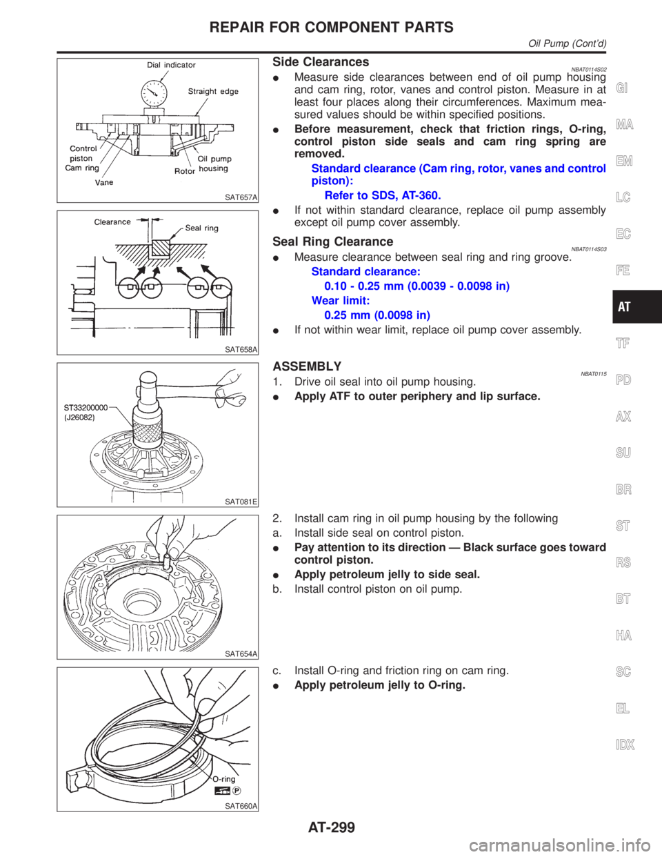
Side ClearancesNBAT0114S02IMeasure side clearances between end of oil pump housing
and cam ring, rotor, vanes and control piston. Measure in at
least four places along their circumferences. Maximum mea-
sured values should be within specified positions.
IBefore measurement, check that friction rings, O-ring,
control piston side seals and cam ring spring are
removed.
Standard clearance (Cam ring, rotor, vanes and control
piston):
Refer to SDS, AT-360.
IIf not within standard clearance, replace oil pump assembly
except oil pump cover assembly.
Seal Ring ClearanceNBAT0114S03IMeasure clearance between seal ring and ring groove.
Standard clearance:
0.10 - 0.25 mm (0.0039 - 0.0098 in)
Wear limit:
0.25 mm (0.0098 in)
IIf not within wear limit, replace oil pump cover assembly.
SAT081E
ASSEMBLYNBAT01151. Drive oil seal into oil pump housing.
IApply ATF to outer periphery and lip surface.
SAT654A
2. Install cam ring in oil pump housing by the following
a. Install side seal on control piston.
IPay attention to its direction Ð Black surface goes toward
control piston.
IApply petroleum jelly to side seal.
b. Install control piston on oil pump.
SAT660A
c. Install O-ring and friction ring on cam ring.
IApply petroleum jelly to O-ring.
GI
MA
EM
LC
EC
FE
TF
PD
AX
SU
BR
ST
RS
BT
HA
SC
EL
IDX
REPAIR FOR COMPONENT PARTS
Oil Pump (Cont'd)
AT-299


