IDX INFINITI QX4 2001 Factory Service Manual
[x] Cancel search | Manufacturer: INFINITI, Model Year: 2001, Model line: QX4, Model: INFINITI QX4 2001Pages: 2395, PDF Size: 43.2 MB
Page 386 of 2395
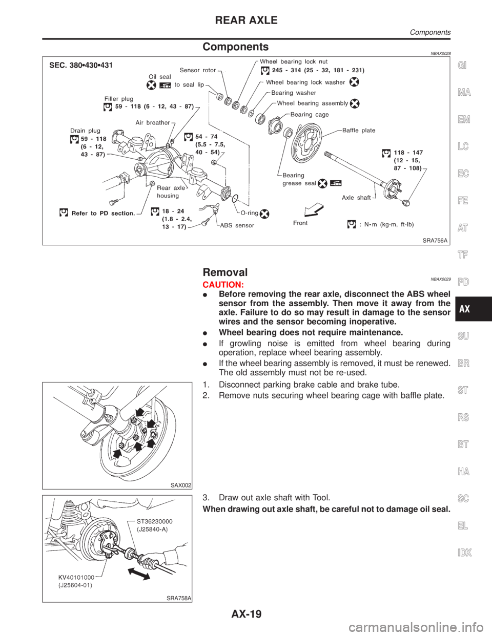
ComponentsNBAX0028
SRA756A
RemovalNBAX0029CAUTION:
IBefore removing the rear axle, disconnect the ABS wheel
sensor from the assembly. Then move it away from the
axle. Failure to do so may result in damage to the sensor
wires and the sensor becoming inoperative.
IWheel bearing does not require maintenance.
IIf growling noise is emitted from wheel bearing during
operation, replace wheel bearing assembly.
IIf the wheel bearing assembly is removed, it must be renewed.
The old assembly must not be re-used.
SAX002
1. Disconnect parking brake cable and brake tube.
2. Remove nuts securing wheel bearing cage with baffle plate.
SRA758A
3. Draw out axle shaft with Tool.
When drawing out axle shaft, be careful not to damage oil seal.
GI
MA
EM
LC
EC
FE
AT
TF
PD
SU
BR
ST
RS
BT
HA
SC
EL
IDX
REAR AXLE
Components
AX-19
Page 388 of 2395
InspectionNBAX0030AXLE SHAFTNBAX0030S01Check axle shaft for straightness, cracks, damage, wear and dis-
tortion. Replace if necessary.
BEARING CAGENBAX0030S02Check bearing cage for deformation and cracks. Replace if neces-
sary.
REAR AXLE HOUSINGNBAX0030S03Check rear axle housing for yield, deformation and cracks. Replace
if necessary.
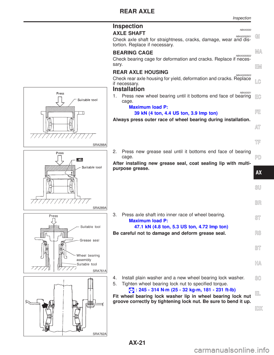
SRA288A
InstallationNBAX00311. Press new wheel bearing until it bottoms end face of bearing
cage.
Maximum load P:
39 kN (4 ton, 4.4 US ton, 3.9 Imp ton)
Always press outer race of wheel bearing during installation.
SRA289A
2. Press new grease seal until it bottoms end face of bearing
cage.
After installing new grease seal, coat sealing lip with multi-
purpose grease.
SRA761A
3. Press axle shaft into inner race of wheel bearing.
Maximum load P:
47.1 kN (4.8 ton, 5.3 US ton, 4.72 Imp ton)
Be careful not to damage and deform grease seal.
SRA762A
4. Install plain washer and a new wheel bearing lock washer.
5. Tighten wheel bearing lock nut to specified torque.
: 245 - 314 N´m (25 - 32 kg-m, 181 - 231 ft-lb)
Fit wheel bearing lock washer lip in wheel bearing lock nut
groove correctly by tightening lock nut. Be sure to bend it up.
GI
MA
EM
LC
EC
FE
AT
TF
PD
SU
BR
ST
RS
BT
HA
SC
EL
IDX
REAR AXLE
Inspection
AX-21
Page 390 of 2395

BRAKE SYSTEM
SECTION
BR
CONTENTS
PRECAUTIONS...............................................................3
Supplemental Restraint System (SRS)²AIR
BAG²and²SEAT BELT PRE-TENSIONER²...............3
Precautions for Brake System .....................................3
Wiring Diagrams and Trouble Diagnoses....................4
PREPARATION...............................................................5
Special Service Tools ..................................................5
Commercial Service Tools ...........................................5
NOISE, VIBRATION AND HARSHNESS (NVH)
TROUBLESHOOTING.....................................................6
NVH Troubleshooting Chart.........................................6
ON-VEHICLE SERVICE..................................................7
Checking Brake Fluid Level.........................................7
Checking Brake Line ...................................................7
Changing Brake Fluid ..................................................7
Bleeding Brake System ...............................................8
BRAKE HYDRAULIC LINE.............................................9
Hydraulic Circuit...........................................................9
Removal .....................................................................10
Inspection...................................................................10
Installation ..................................................................10
PROPORTIONING VALVE (2WD)................................ 11
Inspection................................................................... 11
Removal and Installation (Built-in type)..................... 11
LOAD SENSING VALVE (4WD)...................................12
Inspection...................................................................12
Removal and Installation ...........................................12
BRAKE PEDAL AND BRACKET..................................14
Removal and Installation ...........................................14
Inspection...................................................................14
Adjustment .................................................................14
MASTER CYLINDER.....................................................16
Removal .....................................................................16
Disassembly...............................................................16
Inspection...................................................................17
Assembly ...................................................................17
Installation ..................................................................18
BRAKE BOOSTER........................................................19
On-vehicle Service.....................................................19OPERATING CHECK...............................................19
AIRTIGHT CHECK...................................................19
Removal .....................................................................19
Inspection...................................................................19
OUTPUT ROD LENGTH CHECK..............................19
Installation ..................................................................20
VACUUM PIPING...........................................................21
Vacuum Hose ............................................................21
Removal and Installation ...........................................21
Inspection...................................................................21
HOSES AND CONNECTORS...................................21
CHECK VALVE........................................................21
FRONT DISC BRAKE...................................................22
Components...............................................................22
Pad Replacement ......................................................22
Removal .....................................................................23
Disassembly...............................................................24
Inspection...................................................................24
CALIPER.................................................................24
ROTOR...................................................................24
Assembly ...................................................................25
Installation ..................................................................25
Brake Burnishing Procedure......................................25
REAR DRUM BRAKE...................................................26
Components...............................................................26
Removal .....................................................................26
Inspection...................................................................27
WHEEL CYLINDER..................................................27
Wheel Cylinder Overhaul...........................................28
Inspection...................................................................28
DRUM.....................................................................28
LINING....................................................................28
Installation ..................................................................28
PARKING BRAKE CONTROL......................................30
Components...............................................................30
Removal and Installation ...........................................30
Inspection...................................................................30
Adjustment .................................................................31
GI
MA
EM
LC
EC
FE
AT
TF
PD
AX
SU
ST
RS
BT
HA
SC
EL
IDX
Page 392 of 2395
Supplemental Restraint System (SRS) ªAIR
BAGº and ªSEAT BELT PRE-TENSIONERº
NBBR0001The Supplemental Restraint System such as ªAIR BAGº and ªSEAT BELT PRE-TENSIONERº used along with
a seat belt, helps to reduce the risk or severity of injury to the driver and front passenger for certain types of
collision. The SRS system composition which is available to INFINITI QX4 is as follows:
IFor a frontal collision
The Supplemental Restraint System consists of driver air bag module (located in the center of the steer-
ing wheel), front passenger air bag module (located on the instrument panel on passenger side), seat belt
pre-tensioners, a diagnosis sensor unit, warning lamp, wiring harness and spiral cable.
IFor a side collision
The Supplemental Restraint System consists of side air bag module (located in the outer side of front seat),
satellite sensor, diagnosis sensor unit (one of components of air bags for a frontal collision), wiring harness,
warning lamp (one of components of air bags for a frontal collision).
Information necessary to service the system safely is included in theRS sectionof this Service Manual.
WARNING:
ITo avoid rendering the SRS inoperative, which could increase the risk of personal injury or death
in the event of a collision which would result in air bag inflation, all maintenance must be performed
by an authorized INFINITI dealer.
IImproper maintenance, including incorrect removal and installation of the SRS, can lead to per-
sonal injury caused by unintentional activation of the system. For removal of Spiral Cable and Air
Bag Module, see the RS section.
IDo not use electrical test equipment on any circuit related to the SRS unless instructed to in this
Service Manual. Spiral cable and wiring harnesses covered with yellow insulation tape either just
before the harness connectors or for the complete harness are related to the SRS.
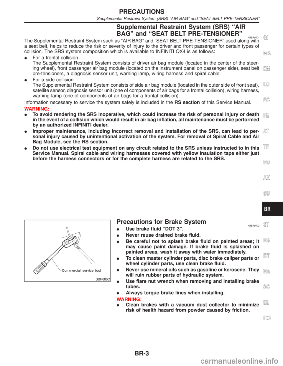
SBR686C
Precautions for Brake SystemNBBR0002IUse brake fluid ªDOT 3º.
INever reuse drained brake fluid.
IBe careful not to splash brake fluid on painted areas; it
may cause paint damage. If brake fluid is splashed on
painted areas, wash it away with water immediately.
ITo clean master cylinder parts, disc brake caliper parts or
wheel cylinder parts, use clean brake fluid.
INever use mineral oils such as gasoline or kerosene. They
will ruin rubber parts of hydraulic system.
IUse flare nut wrench when removing and installing brake
tubes.
IAlways torque brake lines when installing.
WARNING:
IClean brakes with a vacuum dust collector to minimize
risk of health hazard from powder caused by friction.
GI
MA
EM
LC
EC
FE
AT
TF
PD
AX
SU
ST
RS
BT
HA
SC
EL
IDX
PRECAUTIONS
Supplemental Restraint System (SRS) ªAIR BAGº and ªSEAT BELT PRE-TENSIONERº
BR-3
Page 394 of 2395
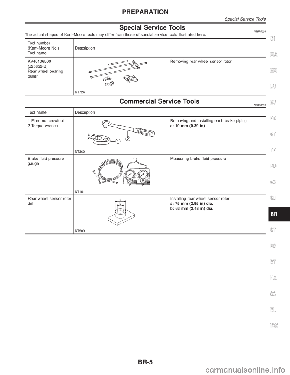
Special Service ToolsNBBR0004The actual shapes of Kent-Moore tools may differ from those of special service tools illustrated here.
Tool number
(Kent-Moore No.)
Tool nameDescription
KV40106500
(J25852-B)
Rear wheel bearing
puller
NT724
Removing rear wheel sensor rotor
Commercial Service ToolsNBBR0005
Tool name Description
1 Flare nut crowfoot
2 Torque wrench
NT360
Removing and installing each brake piping
a: 10 mm (0.39 in)
Brake fluid pressure
gauge
NT151
Measuring brake fluid pressure
Rear wheel sensor rotor
drift
NT509
Installing rear wheel sensor rotor
a: 75 mm (2.95 in) dia.
b: 63 mm (2.48 in) dia.
GI
MA
EM
LC
EC
FE
AT
TF
PD
AX
SU
ST
RS
BT
HA
SC
EL
IDX
PREPARATION
Special Service Tools
BR-5
Page 396 of 2395
SBR451D
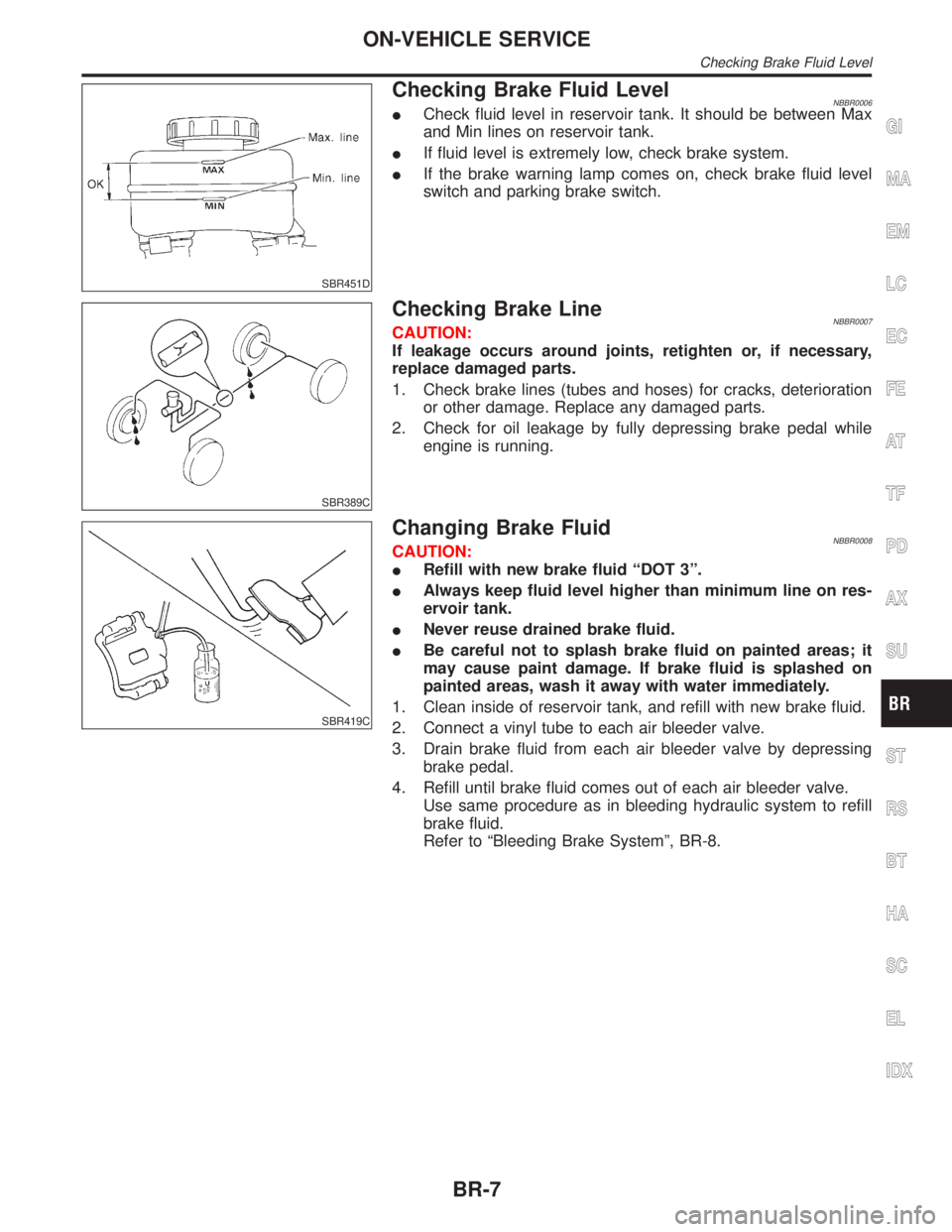
Checking Brake Fluid LevelNBBR0006ICheck fluid level in reservoir tank. It should be between Max
and Min lines on reservoir tank.
IIf fluid level is extremely low, check brake system.
IIf the brake warning lamp comes on, check brake fluid level
switch and parking brake switch.
SBR389C
Checking Brake LineNBBR0007CAUTION:
If leakage occurs around joints, retighten or, if necessary,
replace damaged parts.
1. Check brake lines (tubes and hoses) for cracks, deterioration
or other damage. Replace any damaged parts.
2. Check for oil leakage by fully depressing brake pedal while
engine is running.
SBR419C
Changing Brake FluidNBBR0008CAUTION:
IRefill with new brake fluid ªDOT 3º.
IAlways keep fluid level higher than minimum line on res-
ervoir tank.
INever reuse drained brake fluid.
IBe careful not to splash brake fluid on painted areas; it
may cause paint damage. If brake fluid is splashed on
painted areas, wash it away with water immediately.
1. Clean inside of reservoir tank, and refill with new brake fluid.
2. Connect a vinyl tube to each air bleeder valve.
3. Drain brake fluid from each air bleeder valve by depressing
brake pedal.
4. Refill until brake fluid comes out of each air bleeder valve.
Use same procedure as in bleeding hydraulic system to refill
brake fluid.
Refer to ªBleeding Brake Systemº, BR-8.
GI
MA
EM
LC
EC
FE
AT
TF
PD
AX
SU
ST
RS
BT
HA
SC
EL
IDX
ON-VEHICLE SERVICE
Checking Brake Fluid Level
BR-7
Page 398 of 2395

Hydraulic CircuitNBBR0010
SBR374DA
SBR375DE
GI
MA
EM
LC
EC
FE
AT
TF
PD
AX
SU
ST
RS
BT
HA
SC
EL
IDX
BRAKE HYDRAULIC LINE
Hydraulic Circuit
BR-9
Page 400 of 2395
SBR822BA
InspectionNBBR0116
SBR823BA
SBR705AA
CAUTION:
ICarefully monitor brake fluid level at master cylinder.
IUse new brake fluid ªDOT 3º.
IBe careful not to splash brake fluid on painted areas; it
may cause paint damage. If brake fluid is splashed on
paint areas, wash it away with water immediately.
IDepress pedal slowly when raising front brake pressure.
ICheck rear brake pressure 2 seconds after front brake
pressure reaches specified value.
IDisconnect harness connectors from ABS actuator and
electric unit before checking.
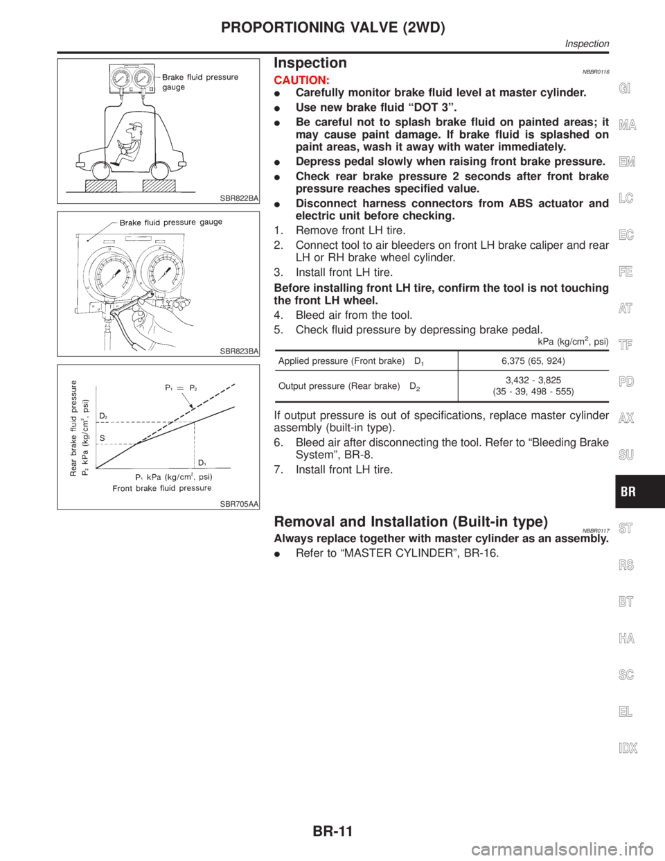
1. Remove front LH tire.
2. Connect tool to air bleeders on front LH brake caliper and rear
LH or RH brake wheel cylinder.
3. Install front LH tire.
Before installing front LH tire, confirm the tool is not touching
the front LH wheel.
4. Bleed air from the tool.
5. Check fluid pressure by depressing brake pedal.
kPa (kg/cm2, psi)
Applied pressure (Front brake) D16,375 (65, 924)
Output pressure (Rear brake) D
23,432 - 3,825
(35 - 39, 498 - 555)
If output pressure is out of specifications, replace master cylinder
assembly (built-in type).
6. Bleed air after disconnecting the tool. Refer to ªBleeding Brake
Systemº, BR-8.
7. Install front LH tire.
Removal and Installation (Built-in type)NBBR0117Always replace together with master cylinder as an assembly.
IRefer to ªMASTER CYLINDERº, BR-16.
GI
MA
EM
LC
EC
FE
AT
TF
PD
AX
SU
ST
RS
BT
HA
SC
EL
IDX
PROPORTIONING VALVE (2WD)
Inspection
BR-11
Page 402 of 2395

SBR379DC
1. Tighten all flare nuts and mounting bolts.
Flare nut:
: 15 - 17 N´m (1.5 - 1.8 kg-m, 11 - 13 ft-lb)
2. Refill until new brake fluid comes out of each air bleeder valve.
3. Bleed air. Refer to ªBleeding Brake Systemº, BR-8.
GI
MA
EM
LC
EC
FE
AT
TF
PD
AX
SU
ST
RS
BT
HA
SC
EL
IDX
LOAD SENSING VALVE (4WD)
Removal and Installation (Cont'd)
BR-13
Page 404 of 2395

SBR824B
1. Loosen lock nut and adjust pedal free height by turning brake
booster input rod. Then tighten lock nut.
Make sure that tip of input rod stays inside.
2. Adjust clearance ªC
1º and ªC2º with stop lamp switch and
ASCD switch respectively. Then tighten lock nuts.
3. Check pedal free play.
Make sure that stop lamp is off when pedal is released.
4. Check brake pedal's depressed height while engine is running.
If depressed height is below specified value, check brake sys-
tem for leaks, accumulation of air or any damage to compo-
nents (master cylinder, wheel cylinder, etc.). Then make nec-
essary repairs.
GI
MA
EM
LC
EC
FE
AT
TF
PD
AX
SU
ST
RS
BT
HA
SC
EL
IDX
BRAKE PEDAL AND BRACKET
Adjustment (Cont'd)
BR-15