IDX INFINITI QX4 2001 Factory Service Manual
[x] Cancel search | Manufacturer: INFINITI, Model Year: 2001, Model line: QX4, Model: INFINITI QX4 2001Pages: 2395, PDF Size: 43.2 MB
Page 346 of 2395

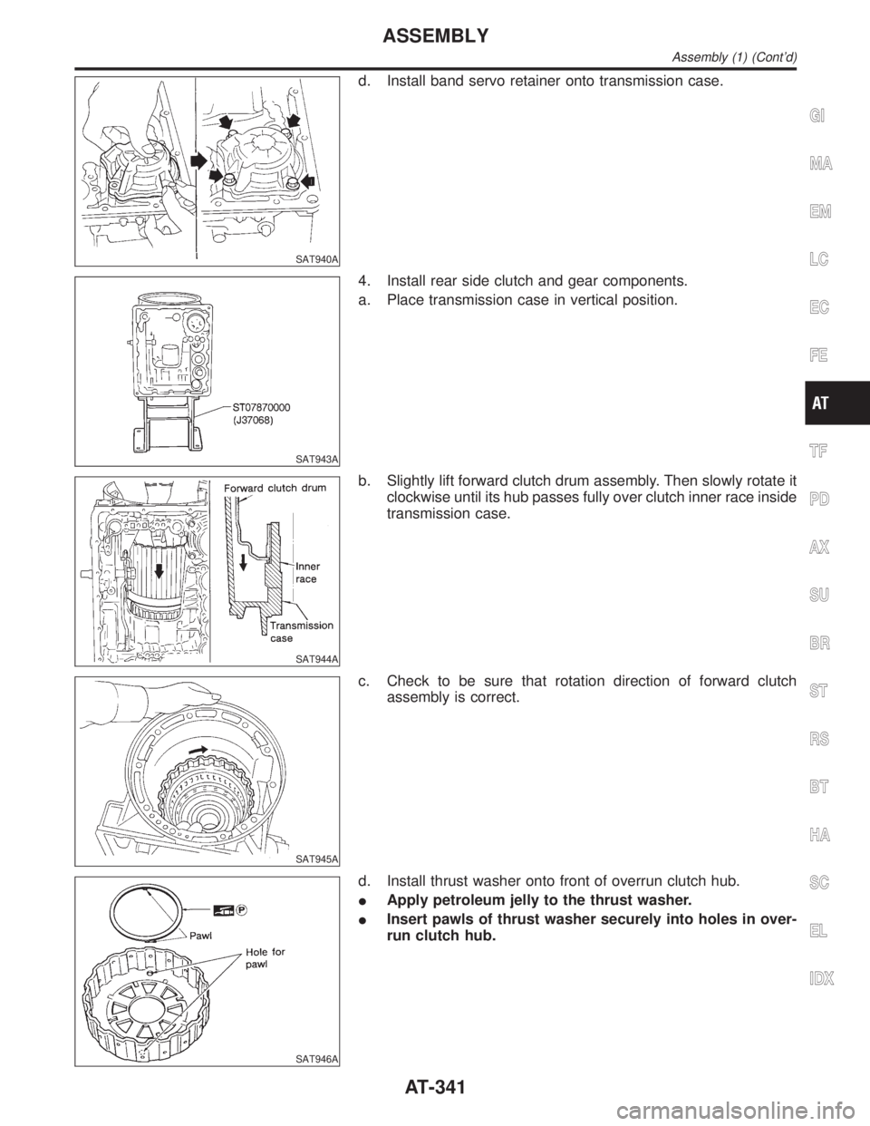
SAT940A
d. Install band servo retainer onto transmission case.
SAT943A
4. Install rear side clutch and gear components.
a. Place transmission case in vertical position.
SAT944A
b. Slightly lift forward clutch drum assembly. Then slowly rotate it
clockwise until its hub passes fully over clutch inner race inside
transmission case.
SAT945A
c. Check to be sure that rotation direction of forward clutch
assembly is correct.
SAT946A
d. Install thrust washer onto front of overrun clutch hub.
IApply petroleum jelly to the thrust washer.
IInsert pawls of thrust washer securely into holes in over-
run clutch hub.
GI
MA
EM
LC
EC
FE
TF
PD
AX
SU
BR
ST
RS
BT
HA
SC
EL
IDX
ASSEMBLY
Assembly (1) (Cont'd)
AT-341
Page 348 of 2395

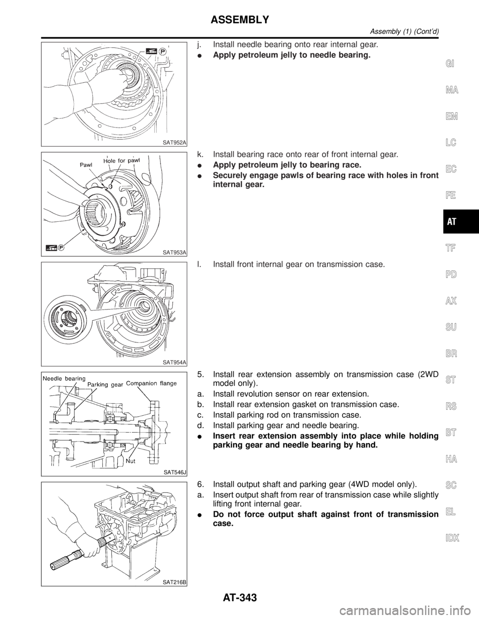
SAT952A
j. Install needle bearing onto rear internal gear.
IApply petroleum jelly to needle bearing.
SAT953A
k. Install bearing race onto rear of front internal gear.
IApply petroleum jelly to bearing race.
ISecurely engage pawls of bearing race with holes in front
internal gear.
SAT954A
l. Install front internal gear on transmission case.
SAT546J
5. Install rear extension assembly on transmission case (2WD
model only).
a. Install revolution sensor on rear extension.
b. Install rear extension gasket on transmission case.
c. Install parking rod on transmission case.
d. Install parking gear and needle bearing.
IInsert rear extension assembly into place while holding
parking gear and needle bearing by hand.
SAT216B
6. Install output shaft and parking gear (4WD model only).
a. Insert output shaft from rear of transmission case while slightly
lifting front internal gear.
IDo not force output shaft against front of transmission
case.
GI
MA
EM
LC
EC
FE
TF
PD
AX
SU
BR
ST
RS
BT
HA
SC
EL
IDX
ASSEMBLY
Assembly (1) (Cont'd)
AT-343
Page 350 of 2395

SAT757I
b. Install O-ring on revolution sensor.
IApply ATF to O-ring.
c. Install revolution sensor on adapter case.
SAT963A
d. Install adapter case gasket on transmission case.
SAT964A
e. Install parking rod on transmission case.
SAT755I
f. Install adapter case on transmission case.
SAT974A
8. Install front side clutch and gear components.
a. Install rear sun gear on transmission case.
IPay attention to its direction.
GI
MA
EM
LC
EC
FE
TF
PD
AX
SU
BR
ST
RS
BT
HA
SC
EL
IDX
ASSEMBLY
Assembly (1) (Cont'd)
AT-345
Page 352 of 2395

Adjustment=NBAT0156When any parts listed in the following table are replaced, total end
play or reverse clutch end play must be adjusted.
Part name Total end play Reverse clutch end play
Transmission caseII
Low one-way clutch inner raceII
Overrun clutch hubII
Rear internal gearII
Rear planetary carrierII
Rear sun gearII
Front planetary carrierII
Front sun gearII
High clutch hubII
High clutch drumII
Oil pump coverII
Reverse clutch drum ÐI
SAT975A
1. Adjust total end play.
Total end play ªT
1º:
0.25 - 0.55 mm (0.0098 - 0.0217 in)
SAT976A
a. With needle bearing installed, place J34291-1 (bridge),
J34291-2 (legs) and the J34291-5 (gauging cylinder) onto oil
pump. The long ends of legs should be placed firmly on
machined surface of oil pump assembly. The gauging cylinder
should rest on top of the needle bearing. Lock gauging cylin-
der in place with set screw.
SAT977A
b. Install J34291-23 (gauging plunger) into gauging cylinder.
GI
MA
EM
LC
EC
FE
TF
PD
AX
SU
BR
ST
RS
BT
HA
SC
EL
IDX
ASSEMBLY
Adjustment
AT-347
Page 354 of 2395

SAT983A
c. Install original thrust washer on oil pump. Place shim setting
gauge legs onto machined surface of oil pump assembly. Allow
gauging plunger to rest on thrust washer. Lock plunger in place
with set screw.
SAT984A
d. Use feeler gauge to measure gap between gauging plunger
and gauging cylinder. This measurement should give you exact
reverse clutch drum end play.
Reverse clutch drum end play ªT
2º:
0.55 - 0.90 mm (0.0217 - 0.0354 in)
IIf end play is out of specification, decrease or increase thick-
ness of oil pump thrust washer as necessary.
Available oil pump thrust washer:
Refer to SDS, AT-361.
SAT985A
Assembly (2)NBAT01571. Install brake band and band strut.
a. Install band strut on brake band.
IApply petroleum jelly to band strut.
SAT986A
b. Place brake band on periphery of reverse clutch drum, and
insert band strut into end of band servo piston stem.
SAT987A
c. Install anchor end bolt on transmission case. Then, tighten
anchor end bolt just enough so that reverse clutch drum (clutch
pack) will not tilt forward.
GI
MA
EM
LC
EC
FE
TF
PD
AX
SU
BR
ST
RS
BT
HA
SC
EL
IDX
ASSEMBLY
Adjustment (Cont'd)
AT-349
Page 356 of 2395

SAT993A
f. Install oil pump assembly.
IInstall two converter housing securing bolts in bolt holes
in oil pump assembly as guides.
SAT994A
IInsert oil pump assembly to the specified position in
transmission, as shown at left.
SAT114B
5. Install O-ring on input shaft.
IApply ATF to O-rings.
SAT397C
6. Install converter housing.
a. Apply recommended sealant (Genuine anaerobic liquid
gasket, Three Bond TB1215, Locktite Part No. 51813 or
equivalent) to outer periphery of bolt holes in converter hous-
ing.
IDo not apply too much sealant.
SAT158G
b. Apply recommended sealant (Genuine anaerobic liquid
gasket, Three Bond TB1215, Locktite Part No. 51813 or
equivalent) to seating surfaces of bolts that secure front of
converter housing.
c. Install converter housing on transmission case.
GI
MA
EM
LC
EC
FE
TF
PD
AX
SU
BR
ST
RS
BT
HA
SC
EL
IDX
ASSEMBLY
Assembly (2) (Cont'd)
AT-351
Page 358 of 2395

SAT006B
c. Place control valve assembly on transmission case. Connect
solenoid connector for upper body.
d. Install connector clip.
SAT353B
e. Install control valve assembly on transmission case.
f. Install connector tube brackets and tighten bolts A and B.
ICheck that terminal assembly does not catch.
Bolt symbolmm (in)
A 33 (1.30)
B 45 (1.77)
SAT221B
g. Install O-ring on oil strainer.
IApply petroleum jelly to O-ring.
h. Install oil strainer on control valve.
SAT009B
i. Securely fasten terminal harness with clips.
GI
MA
EM
LC
EC
FE
TF
PD
AX
SU
BR
ST
RS
BT
HA
SC
EL
IDX
ASSEMBLY
Assembly (2) (Cont'd)
AT-353
Page 360 of 2395

SAT428DA
13. Install torque converter.
a. Pour ATF into torque converter.
IApproximately 2 liters (2-1/8 US qt, 1-3/4 Imp qt) of fluid
are required for a new torque converter.
IWhen reusing old torque converter, add the same amount
of fluid as was drained.
SAT016B
b. Install torque converter while aligning notches and oil pump.
SAT017B
c. Measure distance A to check that torque converter is in proper
position.
Distance ªAº:
25.0 mm (0.984 in) or more
GI
MA
EM
LC
EC
FE
TF
PD
AX
SU
BR
ST
RS
BT
HA
SC
EL
IDX
ASSEMBLY
Assembly (2) (Cont'd)
AT-355
Page 362 of 2395

Return SpringsNBAT0165Unit: mm (in)
PartsItem
Part No.* Free length Outer diameter
Control valveUpper body1 Torque converter relief valve spring 31742-41X23 38.0 (1.496) 9.0 (0.354)
2 Pressure regulator valve spring 31742-41X24 44.02 (1.7331) 14.0 (0.551)
3 Pressure modifier valve spring 31742-41X19 31.95 (1.2579) 6.8 (0.268)
Ð Accumulator control valve spring Ð Ð Ð
4 Shuttle shift valve D spring 31762-41X01 25.0 (0.984) 7.0 (0.276)
5 4-2 sequence valve spring 31756-41X00 29.1 (1.146) 6.95 (0.2736)
6 Shift valve B spring 31762-41X01 25.0 (0.984) 7.0 (0.276)
7 4-2 relay valve spring 31756-41X00 29.1 (1.146) 6.95 (0.2736)
8 Shift valve A spring 31762-41X01 25.0 (0.984) 7.0 (0.276)
9 Overrun clutch control valve spring 31762-41X03 23.6 (0.929) 7.0 (0.276)
10 Overrun clutch reducing valve spring 31742-41X14 38.9 (1.531) 7.0 (0.276)
11 Shuttle shift valve S spring 31762-41X04 51.0 (2.008) 5.65 (0.2224)
12 Pilot valve spring 31742-41X13 25.7 (1.012) 9.0 (0.354)
13 Torque converter clutch control valve spring 31742-41X22 18.5 (0.728) 13.0 (0.512)
Lower body1 Modifier accumulator piston spring 31742-27X70 31.4 (1.236) 9.8 (0.386)
2 1st reducing valve spring 31756-60X00 20.5 (0.807) 7.0 (0.276)
3 3-2 timing valve spring 31742-41X06 23.0 (0.906) 6.7 (0.264)
4 Servo charger valve spring 31742-41X06 23.0 (0.906) 6.7 (0.264)
Reverse clutch Ð 31505-41X07 Ð Ð
High clutch10 pcs31521-41X03
(Assembly)24.2 (0.9528) 11.6 (0.457)
Forward clutch (Overrun clutch) 20 pcs31521-41X04
(Assembly)35.77 (1.4083) 9.7 (0.382)
Low & reverse brake 18 pcs31655-41X00
(Assembly)22.3 (0.878) 11.2 (0.441)
Band servoSpring A 31605-4AX03 45.6 (1.795) 34.3 (1.350)
Spring B 31605-41X01 29.7 (1.169) 27.6 (1.087)
AccumulatorAccumulator A 31605-41X02 43.0 (1.693) 18.0 (0.709)
Accumulator B 31605-41X14 47.6 (1.874) 26.5 (1.043)
Accumulator C 31605-41X09 45.0 (1.772) 29.3 (1.154)
Accumulator D 31605-41X06 58.4 (2.299) 17.3 (0.681)
GI
MA
EM
LC
EC
FE
TF
PD
AX
SU
BR
ST
RS
BT
HA
SC
EL
IDX
SERVICE DATA AND SPECIFICATIONS (SDS)
Return Springs
AT-357
Page 364 of 2395

FORWARD CLUTCHNBAT0167S03
Code number 4EX16 4EX17
Number of drive plates 7 8
Number of driven plates 7 8
Thickness of drive
plate mm (in)Standard 1.52 - 1.67 (0.0598 - 0.0657)
Wear limit 1.40 (0.0551)
Clearance mm (in)Standard 0.35 - 0.75 (0.0138 - 0.0295)
Allowable limit 2.15 (0.0846) 2.35 (0.0925)
Thickness of retaining plateThickness mm (in) Part number* Thickness mm (in) Part number*
4.6 (0.181)
4.8 (0.189)
5.0 (0.197)
5.2 (0.205)
5.4 (0.213)
5.6 (0.220)31537-42X13
31537-42X14
31537-42X15
31537-4AX00
31537-4AX01
31537-4AX024.2 (0.165)
4.4 (0.173)
4.6 (0.181)
4.8 (0.189)
5.0 (0.197)
5.2 (0.205)
5.4 (0.213)31537-42X11
31537-42X12
31537-42X13
31537-42X14
31537-42X15
31537-4AX00
31537-4AX01
OVERRUN CLUTCHNBAT0167S04
Code number4EX16 4EX17
Number of drive plates3
Number of driven plates5
Thickness of drive plate mm (in)Standard 1.90 - 2.05 (0.0748 - 0.0807)
Wear limit 1.80 (0.0709)
Clearance mm (in)Standard 1.0 - 1.4 (0.039 - 0.055)
Allowable limit 2.0 (0.079)
Thickness of retaining plateThickness mm (in) Part number*
4.2 (0.165)
4.4 (0.173)
4.6 (0.181)
4.8 (0.189)
5.0 (0.197)31537-41X80
31537-41X81
31537-41X82
31537-41X83
31537-41X84
GI
MA
EM
LC
EC
FE
TF
PD
AX
SU
BR
ST
RS
BT
HA
SC
EL
IDX
SERVICE DATA AND SPECIFICATIONS (SDS)
Clutches and Brakes (Cont'd)
AT-359