INSTALLATION INFINITI QX4 2001 Factory Service Manual
[x] Cancel search | Manufacturer: INFINITI, Model Year: 2001, Model line: QX4, Model: INFINITI QX4 2001Pages: 2395, PDF Size: 43.2 MB
Page 1987 of 2395

SLC334B
15. Install water control valve and water outlet housing.
a. Install gum ring to thermostat.
b. Point the arrow on the upper surface of the valve to the front
of the engine, and also be sure to install the protrusions and
the valve stopper so that they are aligned in a straight line.
16. Reinstall any removed parts in reverse order of removal.
IWhen installing intake manifold, injector tube and intake
manifold collectors, refer to EM-12, ªTIGHTENING PROCE-
DURESº.
IAfter installation, run engine for a few minutes, and check
for leaks.
IBe careful not to spill coolant over engine compartment.
Use a rag to absorb coolant.
SLC252B
INSPECTIONNBLC00331. Check valve seating condition at ordinary room temperatures.
It should seat tightly.
2. Check valve opening temperature and maximum valve lift.
Standard
Valve opening temperature 95ÉC (203ÉF)
Valve lift More than 8.0 mm/108ÉC
(0.315 in/226ÉF)
3. Then check if valve closes at 5ÉC (9ÉF) below valve opening
temperature.
ENGINE COOLING SYSTEM
Water Control Valve (Cont'd)
LC-18
Page 1988 of 2395

Radiator
REMOVAL AND INSTALLATION=NBLC00231. Remove under cover.
2. Remove suspension member stay.
3. Drain coolant from radiator.
4. Disconnect radiator upper and lower hoses.
5. Remove upper and lower radiator shroud.
6. Remove A/T oil cooler hoses.
7. Disconnect reservoir tank hose.
8. Remove radiator mounting bracket.
9. Remove radiator.
10. After repairing or replacing radiator, install any part removed in reverse order of removal.
When filling radiator with coolant, refer to MA-14, ªChanging Engine Coolantº.
SLC331B
GI
MA
EM
EC
FE
AT
TF
PD
AX
SU
BR
ST
RS
BT
HA
SC
EL
IDX
ENGINE COOLING SYSTEM
Radiator
LC-19
Page 1989 of 2395

SLC066B
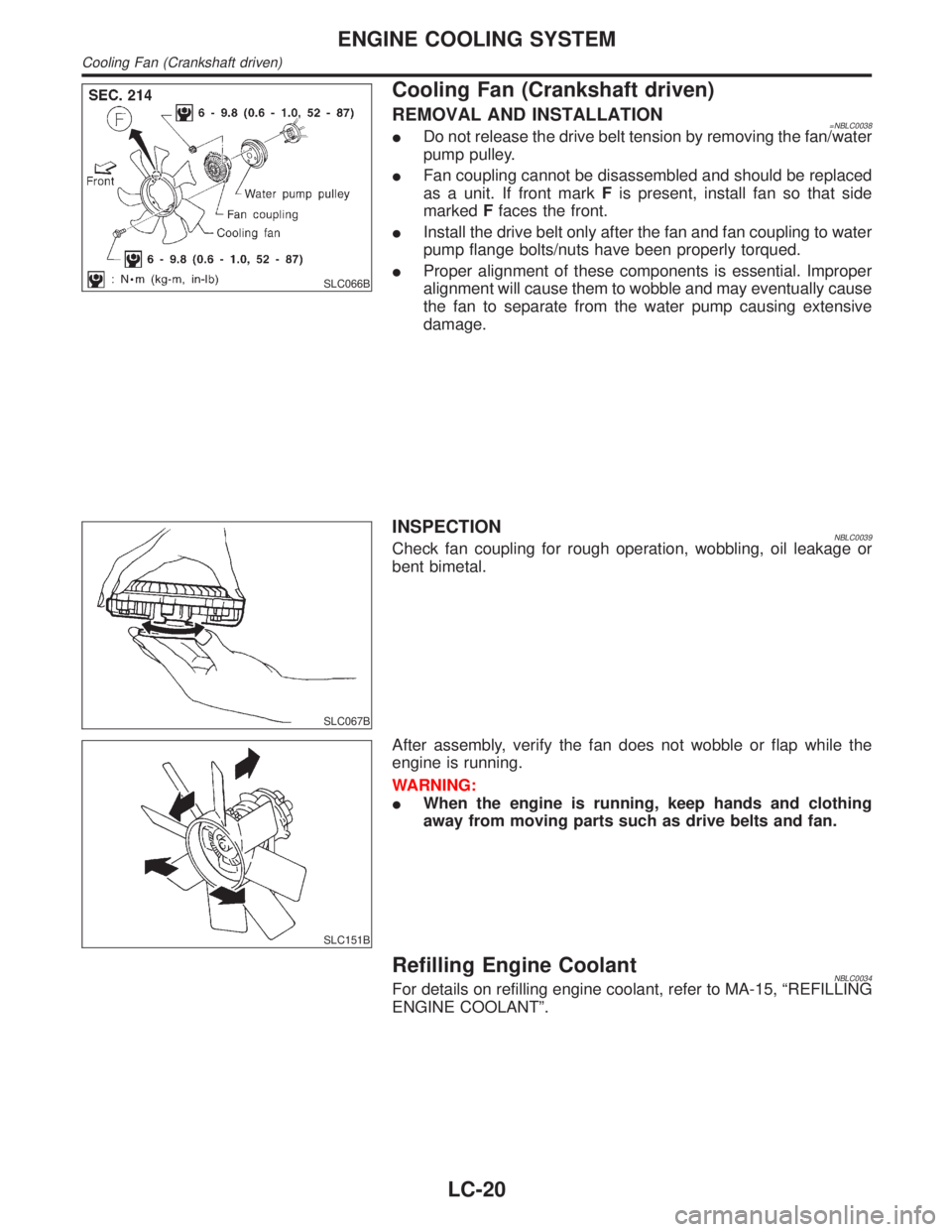
Cooling Fan (Crankshaft driven)
REMOVAL AND INSTALLATION=NBLC0038IDo not release the drive belt tension by removing the fan/water
pump pulley.
IFan coupling cannot be disassembled and should be replaced
as a unit. If front markFis present, install fan so that side
markedFfaces the front.
IInstall the drive belt only after the fan and fan coupling to water
pump flange bolts/nuts have been properly torqued.
IProper alignment of these components is essential. Improper
alignment will cause them to wobble and may eventually cause
the fan to separate from the water pump causing extensive
damage.
SLC067B
INSPECTIONNBLC0039Check fan coupling for rough operation, wobbling, oil leakage or
bent bimetal.
SLC151B
After assembly, verify the fan does not wobble or flap while the
engine is running.
WARNING:
IWhen the engine is running, keep hands and clothing
away from moving parts such as drive belts and fan.
Refilling Engine CoolantNBLC0034For details on refilling engine coolant, refer to MA-15, ªREFILLING
ENGINE COOLANTº.
ENGINE COOLING SYSTEM
Cooling Fan (Crankshaft driven)
LC-20
Page 1997 of 2395

Supplemental Restraint System (SRS) ªAIR
BAGº and ªSEAT BELT PRE-TENSIONERº
NBMA0001The Supplemental Restraint System such as ªAIR BAGº and ªSEAT BELT PRE-TENSIONERº used along with
a seat belt, helps to reduce the risk or severity of injury to the driver and front passenger for certain types of
collision. The SRS system composition which is available to INFINITI QX4 is as follows:
IFor a frontal collision
The Supplemental Restraint System consists of driver air bag module (located in the center of the steer-
ing wheel), front passenger air bag module (located on the instrument panel on passenger side), seat belt
pre-tensioners, a diagnosis sensor unit, warning lamp, wiring harness and spiral cable.
IFor a side collision
The Supplemental Restraint System consists of side air bag module (located in the outer side of front seat),
satellite sensor, diagnosis sensor unit (one of components of air bags for a frontal collision), wiring harness,
warning lamp (one of components of air bags for a frontal collision).
Information necessary to service the system safely is included in theRS sectionof this Service Manual.
WARNING:
ITo avoid rendering the SRS inoperative, which could increase the risk of personal injury or death
in the event of a collision which would result in air bag inflation, all maintenance must be performed
by an authorized INFINITI dealer.
IImproper maintenance, including incorrect removal and installation of the SRS, can lead to per-
sonal injury caused by unintentional activation of the system. For removal of Spiral Cable and Air
Bag Module, see the RS section.
IDo not use electrical test equipment on any circuit related to the SRS unless instructed to in this
Service Manual. Spiral cable and wiring harnesses covered with yellow insulation tape either just
before the harness connectors or for the complete harness are related to the SRS.
PRECAUTIONS
Supplemental Restraint System (SRS) ªAIR BAGº and ªSEAT BELT PRE-TENSIONERº
MA-2
Page 2026 of 2395

PROPELLER SHAFT &
DIFFERENTIAL CARRIER
SECTION
PD
CONTENTS
PROPELLER SHAFT......................................................3
Noise, Vibration and Harshness (NVH)
Troubleshooting ...........................................................3
NVH TROUBLESHOOTING CHART............................3
Components.................................................................4
FRONT PROPELLER SHAFT.....................................4
REAR PROPELLER SHAFT.......................................5
On-vehicle Service.......................................................6
PROPELLER SHAFT VIBRATION...............................6
APPEARANCE CHECKING........................................6
Removal and Installation .............................................6
Inspection.....................................................................7
Disassembly.................................................................7
CENTER BEARING - 2WD -.......................................7
JOURNAL (71H AND 80B)..........................................8
Assembly .....................................................................9
CENTER BEARING - 2WD -.......................................9
JOURNAL (71H AND 80B)..........................................9
Service Data and Specifications (SDS)..................... 11
GENERAL SPECIFICATIONS................................... 11
SERVICE DATA....................................................... 11
SNAP RING (80B).................................................... 11
SNAP RING (71H)...................................................12
R200A
FRONT FINAL DRIVE...................................................13
Preparation ................................................................13
SPECIAL SERVICE TOOLS......................................13
Noise, Vibration and Harshness (NVH)
Troubleshooting .........................................................15
On-vehicle Service.....................................................15
FRONT OIL SEAL REPLACEMENT...........................15
REAR COVER GASKET REPLACEMENT..................16
Components...............................................................17
Removal and Installation ...........................................18
REMOVAL...............................................................18
INSTALLATION........................................................18
Disassembly...............................................................18
PRE-INSPECTION...................................................18
FINAL DRIVE HOUSING..........................................19
DIFFERENTIAL CASE..............................................21
DIFFERENTIAL SIDE SHAFT...................................22
Inspection...................................................................23
RING GEAR AND DRIVE PINION.............................23
DIFFERENTIAL CASE ASSEMBLY...........................23
BEARING................................................................23
Adjustment .................................................................24
SIDE BEARING PRELOAD.......................................24
PINION GEAR HEIGHT AND PINION BEARING
PRELOAD
...............................................................25
TOOTH CONTACT...................................................29
Assembly ...................................................................30
DIFFERENTIAL SIDE SHAFT...................................30
DIFFERENTIAL CASE..............................................31
FINAL DRIVE HOUSING..........................................32
Service Data and Specifications (SDS).....................36
R200A.....................................................................36
H233B
REAR FINAL DRIVE.....................................................38
Preparation ................................................................38
SPECIAL SERVICE TOOLS......................................38
Noise, Vibration and Harshness (NVH)
Troubleshooting .........................................................40
On-vehicle Service.....................................................40
FRONT OIL SEAL REPLACEMENT...........................40
Components...............................................................42
Removal and Installation ...........................................43
REMOVAL...............................................................43
INSTALLATION........................................................43
Disassembly...............................................................43
PRE-INSPECTION...................................................43
DIFFERENTIAL CARRIER........................................44
DIFFERENTIAL CASE..............................................46
Inspection...................................................................47
RING GEAR AND DRIVE PINION.............................47
DIFFERENTIAL CASE ASSEMBLY...........................47
BEARING................................................................47
Limited Slip Differential ..............................................47
PREPARATION FOR DISASSEMBLY........................47
GI
MA
EM
LC
EC
FE
AT
TF
AX
SU
BR
ST
RS
BT
HA
SC
EL
IDX
Page 2031 of 2395

SPD356A
On-vehicle Service
PROPELLER SHAFT VIBRATIONNBPD0003If vibration is present at high speed, inspect propeller shaft runout
first.
1. Raise rear wheels.
2. Measure propeller shaft runout at several points by rotating
final drive companion flange with hands.
Runout limit: 0.6 mm (0.024 in)
SPD523A
Propeller shaft runout measuring points:
Unit: mm (in)
Distance A B C
3F80B-2BJ 372.5 (14.67) 240 (9.45) 240 (9.45)
2S80B-T 280 (11.02) 463.5 (18.25) 266.5 (10.49)
2F71H 173.5 (6.83) Ð Ð
SPD102
3. If runout exceeds specifications, disconnect propeller shaft at
final drive companion flange; then rotate companion flange
180 degrees and reconnect propeller shaft.
4. Check runout again. If runout still exceeds specifications,
replace propeller shaft assembly.
5. Perform road test.
APPEARANCE CHECKINGNBPD0004IInspect propeller shaft tube surface for dents or cracks.
If damaged, replace propeller shaft assembly.
IIf center bearing is noisy or damaged, replace center bearing.
SPD103
Removal and InstallationNBPD0005IPut matchmarks on flanges and separate propeller shaft from
final drive.
PROPELLER SHAFT
On-vehicle Service
PD-6
Page 2032 of 2395

SPD359
IDraw out propeller shaft from transmission and plug up rear
end of transmission rear extension housing.
SPD106
InspectionNBPD0006IInspect propeller shaft runout. If runout exceeds specifications,
replace propeller shaft assembly.
Runout limit: 0.6 mm (0.024 in)
SPD874
IIf the play exceeds specifications, replace propeller shaft
assembly.
Journal axial play:
0.02 mm (0.0008 in) or less
SPD109
DisassemblyNBPD0007CENTER BEARING Ð 2WD ÐNBPD0007S031. Put match marks on flanges, and separate 2nd tube from 1st
tube.
SPD110
2. Put match marks on the flange and shaft.
GI
MA
EM
LC
EC
FE
AT
TF
AX
SU
BR
ST
RS
BT
HA
SC
EL
IDX
PROPELLER SHAFT
Removal and Installation (Cont'd)
PD-7
Page 2043 of 2395

Removal and InstallationNBPD0017REMOVALNBPD0017S01IRemove front of propeller shaft.
Plug front end of transfer.
IRemove drive shaft. Refer to AX-11, ªRemovalº.
IRemove front final drive mounting bolts.
CAUTION:
Be careful not to damage spline, sleeve yoke and front oil seal
when removing propeller shaft.
SPD123
INSTALLATIONNBPD0017S02IFill final drive with recommended gear oil.
SPD664
DisassemblyNBPD0018PRE-INSPECTIONNBPD0018S01Before disassembling final drive, perform the following inspection.
ITotal preload
a) Turn drive pinion in both directions several times to set bear-
ing rollers.
b) Check total preload with Tool.
Tool number: ST3127S000 (J25765-A)
Total preload:
P
1+ [0.3 - 1.5 N´m (3 - 15 kg-cm, 2.6 - 13.0 in-lb)]
P
1: Drive pinion preload
SPD513
IRing gear to drive pinion backlash
Check backlash of ring gear with a dial indicator at several
points.
Ring gear-to-drive pinion backlash:
0.10 - 0.15 mm (0.0039 - 0.0059 in)
FRONT FINAL DRIVER200A
Removal and Installation
PD-18
Page 2068 of 2395

Removal and InstallationNBPD0032REMOVALNBPD0032S01IRemove rear of propeller shaft.
Plug front end of transfer.
IRemove axle shaft.
Refer to AX-19, ªRemovalº.
IRemove rear final drive mounting bolts.
CAUTION:
Be careful not to damage spline, sleeve yoke and front oil seal
when removing propeller shaft.
SPD123
INSTALLATIONNBPD0032S02IFill final drive with recommended gear oil.
SPD767
IPay attention to the direction of gasket.
SPD149
DisassemblyNBPD0033PRE-INSPECTIONNBPD0033S01Before disassembling final drive, perform the following inspection.
ITotal preload
a) Turn drive pinion in both directions several times to seat bear-
ing rollers correctly.
b) Check total preload with Tool.
Tool number: ST3127S000 (J25765-A)
Total preload:
1.2 - 2.0 N´m (12 - 20 kg-cm, 10 - 17 in-lb)
SPD246
IRing gear to drive pinion backlash
Check backlash of ring gear with a dial indicator at several
points.
Ring gear-to-drive pinion backlash:
0.13 - 0.18 mm (0.0051 - 0.0071 in)
GI
MA
EM
LC
EC
FE
AT
TF
AX
SU
BR
ST
RS
BT
HA
SC
EL
IDX
REAR FINAL DRIVEH233B
Removal and Installation
PD-43
Page 2090 of 2395

RESTRAINT SYSTEM
SECTION
RS
CONTENTS
SEAT BELTS...................................................................3
Precautions ..................................................................3
SUPPLEMENTAL RESTRAINT SYSTEM (SRS)
²AIR BAG²AND²SEAT BELT PRE-TENSIONER²
........3
PRECAUTION FOR SEAT BELT SERVICE..................3
Front Seat Belt.............................................................4
REMOVAL AND INSTALLATION.................................4
Rear Seat Belt .............................................................5
REMOVAL AND INSTALLATION.................................5
Seat Belt Inspection.....................................................7
AFTER A COLLISION.................................................7
PRELIMINARY CHECKS............................................7
SEAT BELT RETRACTOR ON-VEHICLE CHECK.........8
SEAT BELT RETRACTOR OFF-VEHICLE CHECK.......8
SUPPLEMENTAL RESTRAINT SYSTEM (SRS).........10
Precautions ................................................................10
SUPPLEMENTAL RESTRAINT SYSTEM (SRS)
²AIR BAG²AND²SEAT BELT PRE-TENSIONER²
......10
PRECAUTIONS FOR SRS²AIR BAG²AND²SEAT
BELT PRE-TENSIONER²SERVICE
...........................10
WIRING DIAGRAMS AND TROUBLE DIAGNOSIS.....10
Preparation ................................................................ 11
SPECIAL SERVICE TOOLS...................................... 11
Description .................................................................12
Seat Belt Pre-tensioner with Load Limiter.................12
Built-in Type Side Air Bag..........................................13
SRS Component Parts Location ...............................13
Maintenance Items ....................................................14
Diagnosis Sensor Unit ...............................................15
REMOVAL AND INSTALLATION...............................15
Seat Belt Pre-tensioner .............................................15
REMOVAL AND INSTALLATION...............................15
Satellite Sensor..........................................................16
REMOVAL AND INSTALLATION...............................16
Driver Air Bag Module and Spiral Cable ...................17
REMOVAL AND INSTALLATION...............................17
REMOVAL...............................................................17
INSTALLATION........................................................18
Front Passenger Air Bag Module ..............................19
REMOVAL...............................................................19
INSTALLATION........................................................20
Side Air Bag Module ..................................................21
REMOVAL...............................................................21
INSTALLATION........................................................22
Disposal of Air Bag Module and Seat Belt Pre-
tensioner ....................................................................22
CHECKING DEPLOYMENT TOOL.............................23
DEPLOYMENT PROCEDURES FOR AIR BAG
MODULE (OUTSIDE OF VEHICLE)
...........................24
DEPLOYMENT PROCEDURES FOR SEAT BELT
PRE-TENSIONER (OUTSIDE OF VEHICLE)
..............27
DEPLOYMENT OF AIR BAG MODULE AND SEAT
BELT PRE-TENSIONER WHILE MOUNTED IN
VEHICLE
.................................................................27
DISPOSING OF AIR BAG MODULE AND SEAT
BELT PRE-TENSIONER
...........................................28
Trouble Diagnoses Introduction.................................29
DIAGNOSIS FUNCTION...........................................29
DIAGNOSIS MODE FOR CONSULT-II.......................29
HOW TO CHANGE SELF-DIAGNOSIS MODE
WITH CONSULT-II
...................................................30
HOW TO CHANGE SELF-DIAGNOSIS MODE
WITHOUT CONSULT-II
............................................30
HOW TO ERASE SELF-DIAGNOSIS RESULTS.........30
How to Perform Trouble Diagnoses for Quick
and Accurate Repair ..................................................32
INFORMATION FROM CUSTOMER..........................32
PRELIMINARY CHECK............................................32
WORK FLOW..........................................................33
Schematic ..................................................................34
Wiring Diagram - SRS -.............................................35
SRS Operation Check ...............................................38
DIAGNOSTIC PROCEDURE 1..................................38
Trouble Diagnoses with CONSULT-II...................39
DIAGNOSTIC PROCEDURE 2..................................39
DIAGNOSTIC PROCEDURE 3..................................42
DIAGNOSTIC PROCEDURE 4 (CONTINUED
FROM DIAGNOSTIC PROCEDURE 2)
......................44
DIAGNOSTIC PROCEDURE 5..................................44
Trouble Diagnoses without CONSULT-II..............48
DIAGNOSTIC PROCEDURE 6..................................48
GI
MA
EM
LC
EC
FE
AT
TF
PD
AX
SU
BR
ST
BT
HA
SC
EL
IDX