lock INFINITI QX4 2001 Factory Owner's Manual
[x] Cancel search | Manufacturer: INFINITI, Model Year: 2001, Model line: QX4, Model: INFINITI QX4 2001Pages: 2395, PDF Size: 43.2 MB
Page 59 of 2395

DIAGNOSTIC WORKSHEET=NBAT0019S01Information From CustomerNBAT0019S0101KEY POINTS
WHAT..... Vehicle & A/T model
WHEN..... Date, Frequencies
WHERE..... Road conditions
HOW..... Operating conditions, Symptoms
Customer name MR/MS Model & Year VIN
Trans. model Engine Mileage
Incident Date Manuf. Date In Service Date
FrequencylContinuouslIntermittent ( times a day)
SymptomslVehicle does not move. (lAny positionlParticular position)
lNo up-shift (l1st,2ndl2nd,3rdl3rd,O/D)
lNo down-shift (lO/D,3rdl3rd,2ndl2nd,1st)
lLockup malfunction
lShift point too high or too low.
lShift shock or slip (lN,DlLockuplAny drive position)
lNoise or vibration
lNo kickdown
lNo pattern select
lOthers
()
O/D OFF indicator lamp Blinks for about 8 seconds.
lContinuously litlNot lit
Malfunction indicator lamp (MIL)lContinuously litlNot lit
TROUBLE DIAGNOSIS Ð INTRODUCTION
Introduction (Cont'd)
AT-54
Page 61 of 2395

4. 4-3. Cruise testAT-67
AT-71
Part-1
l8. Vehicle Cannot Be Started From D
1, AT-233.
l9. A/T Does Not Shift: D
1,D2Or Does Not Kickdown: D4,D2, AT-236.
l10. A/T Does Not Shift: D
2,D3, AT-239.
l11. A/T Does Not Shift: D
3,D4, AT-242.
l12. A/T Does Not Perform Lock-up, AT-245.
l13. A/T Does Not Hold Lock-up Condition, AT-247.
l14. Lock-up Is Not Released, AT-249.
l15. Engine Speed Does Not Return To Idle (Light Braking D
4,D3), AT-250.
Part-2AT-75
l16. Vehicle Does Not Start From D
1, AT-252.
l9. A/T Does Not Shift: D
1,D2Or Does Not Kickdown: D4,D2, AT-236.
l10. A/T Does Not Shift: D
2,D3, AT-239.
l11. A/T Does Not Shift: D
3,D4, AT-242.
Part-3AT-77
l17. A/T Does Not Shift: D
4,D3When Overdrive Control Switch ªONº,ªOFFº, AT-253
l15. Engine Speed Does Not Return To Idle (Engine Brake In D
3), AT-250.
l18. A/T Does Not Shift: D
3,22, When Selector Lever ªDº,ª2º Position, AT-254.
l15. Engine Speed Does Not Return To Idle (Engine Brake In 2
2), AT-250.
l19. A/T Does Not Shift: 2
2,11, When Selector Lever ª2º,ª1º Position, AT-255.
l20. Vehicle Does Not Decelerate By Engine Brake, AT-256.
lSELF-DIAGNOSTIC PROCEDURE Ð Mark detected items.
lDTC P0705 PNP switch, AT-99.
lDTC P0710 A/T fluid temperature sensor, AT-105.
lDTC P0720 Vehicle speed sensor´A/T (Revolution sensor), AT-111.
lDTC P0725 Engine speed signal, AT-116.
lDTC P0740 Torque converter clutch solenoid valve, AT-148.
lDTC P0745 Line pressure solenoid valve, AT-162.
lDTC P0750 Shift solenoid valve A, AT-168.
lDTC P0755 Shift solenoid valve B, AT-172.
lDTC P1705 Throttle position sensor, AT-176.
lDTC P1760 Overrun clutch solenoid valve, AT-185.
lDTC BATT/FLUID TEMP SEN (A/T fluid temperature sensor and TCM power source), AT-190.
lDTC Vehicle speed sensor´MTR, AT-197.
lDTC Turbine revolution sensor, AT-202.
lDTC A/T communication line, AT-207.
lDTC Control unit (RAM), control unit (ROM), AT-211.
lDTC Control unit (EEP ROM), AT-213.
lPNP, overdrive control and throttle position switches, AT-257.
lBattery
lOthers
5.lFor self-diagnosis NG items, inspect each component. Repair or replace the damaged parts. AT-38
6.lPerform all ROAD TEST and re-mark required procedures. AT-63
7.lPerform DTC CONFIRMATION PROCEDURE for following MIL indicating items and check out NG items.
Refer to EC-60, ªEmission-related Diagnostic Informationº.EC-60
lDTC (P0731, 1103) A/T 1st gear function, AT-120.
lDTC (P0732, 1104) A/T 2nd gear function, AT-126.
lDTC (P0733, 1105) A/T 3rd gear function, AT-132.
lDTC (P0734, 1106) A/T 4th gear function, AT-138.
lDTC (P0744, 1107) A/T TCC S/V function (lock-up), AT-153.
8.lPerform the Diagnostic Procedures for all remaining items marked NG. Repair or replace the damaged
parts.
Refer to the Symptom Chart when you perform the procedures. (The chart also shows some other possible
symptoms and the component inspection orders.)AT-92
AT-97
9.lErase DTC from TCM and ECM memories. AT-35
TROUBLE DIAGNOSIS Ð INTRODUCTION
Introduction (Cont'd)
AT-56
Page 64 of 2395

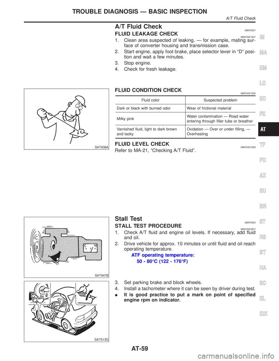
A/T Fluid CheckNBAT0021FLUID LEAKAGE CHECKNBAT0021S011. Clean area suspected of leaking. Ð for example, mating sur-
face of converter housing and transmission case.
2. Start engine, apply foot brake, place selector lever in ªDº posi-
tion and wait a few minutes.
3. Stop engine.
4. Check for fresh leakage.
SAT638A
FLUID CONDITION CHECKNBAT0021S02
Fluid color Suspected problem
Dark or black with burned odor Wear of frictional material
Milky pinkWater contamination Ð Road water
entering through filler tube or breather
Varnished fluid, light to dark brown
and tackyOxidation Ð Over or under filling, Ð
Overheating
FLUID LEVEL CHECKNBAT0021S03Refer to MA-21, ªChecking A/T Fluidº.
SAT647B
Stall TestNBAT0022STALL TEST PROCEDURENBAT0022S011. Check A/T fluid and engine oil levels. If necessary, add fluid
and oil.
2. Drive vehicle for approx. 10 minutes or until fluid and oil reach
operating temperature.
ATF operating temperature:
50 - 80ÉC (122 - 176ÉF)
SAT513G
3. Set parking brake and block wheels.
4. Install a tachometer where it can be seen by driver during test.
IIt is good practice to put a mark on point of specified
engine rpm on indicator.
GI
MA
EM
LC
EC
FE
TF
PD
AX
SU
BR
ST
RS
BT
HA
SC
EL
IDX
TROUBLE DIAGNOSIS Ð BASIC INSPECTION
A/T Fluid Check
AT-59
Page 67 of 2395

SAT209GA
Line Pressure TestNBAT0023ILocation of line pressure test ports.
IAlways replace line pressure plugs as they are self-seal-
ing bolts.
SAT647B
LINE PRESSURE TEST PROCEDURENBAT0023S011. Check A/T fluid and engine oil levels. If necessary, add fluid
and oil.
2. Drive vehicle for approx. 10 minutes or until fluid and oil reach
operating temperature.
ATF operating temperature:
50 - 80ÉC (122 - 176ÉF)
SAT518GB
SAT519GB
3. Install pressure gauge to corresponding line pressure port.
SAT513G
4. Set parking brake and block wheels.
IContinue to depress brake pedal fully while line pressure
test is being performed at stall speed.
TROUBLE DIAGNOSIS Ð BASIC INSPECTION
Line Pressure Test
AT-62
Page 72 of 2395

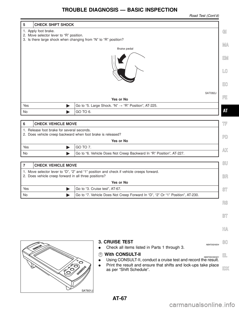
5 CHECK SHIFT SHOCK
1. Apply foot brake.
2. Move selector lever to ªRº position.
3. Is there large shock when changing from ªNº to ªRº position?
SAT082J
YesorNo
Ye s©Go to ª5. Large Shock. ªNº,ªRº Positionº, AT-225.
No©GO TO 6.
6 CHECK VEHICLE MOVE
1. Release foot brake for several seconds.
2. Does vehicle creep backward when foot brake is released?
YesorNo
Ye s©GO TO 7.
No©Go to ª6. Vehicle Does Not Creep Backward In ªRº Positionº, AT-227.
7 CHECK VEHICLE MOVE
1. Move selector lever to ªDº, ª2º and ª1º position and check if vehicle creeps forward.
2. Does vehicle creep forward in all three positions?
YesorNo
Ye s©Go to ª3. Cruise testº, AT-67.
No©Go to ª7. Vehicle Does Not Creep Forward In ªDº, ª2º Or ª1º Positionº, AT-230.
SAT601J
3. CRUISE TESTNBAT0024S04ICheck all items listed in Parts 1 through 3.
With CONSULT-IINBAT0024S0401IUsing CONSULT-II, conduct a cruise test and record the result.
IPrint the result and ensure that shifts and lock-ups take place
as per ªShift Scheduleº.
GI
MA
EM
LC
EC
FE
TF
PD
AX
SU
BR
ST
RS
BT
HA
SC
EL
IDX
TROUBLE DIAGNOSIS Ð BASIC INSPECTION
Road Test (Cont'd)
AT-67
Page 78 of 2395

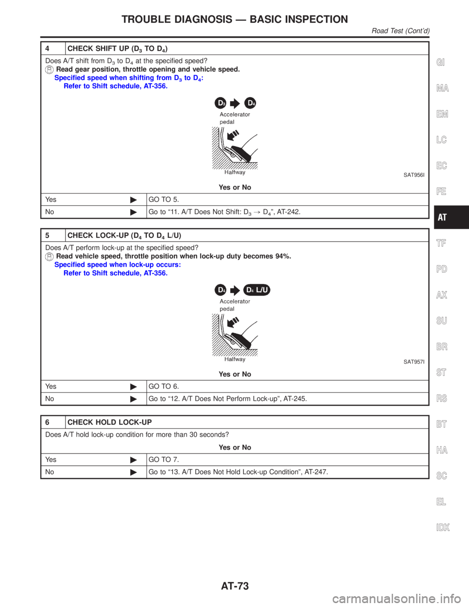
4 CHECK SHIFT UP (D3TO D4)
Does A/T shift from D3to D4at the specified speed?
Read gear position, throttle opening and vehicle speed.
Specified speed when shifting from D
3to D4:
Refer to Shift schedule, AT-356.
SAT956I
YesorNo
Ye s©GO TO 5.
No©Go to ª11. A/T Does Not Shift: D
3,D4º, AT-242.
5 CHECK LOCK-UP (D4TO D4L/U)
Does A/T perform lock-up at the specified speed?
Read vehicle speed, throttle position when lock-up duty becomes 94%.
Specified speed when lock-up occurs:
Refer to Shift schedule, AT-356.
SAT957I
YesorNo
Ye s©GO TO 6.
No©Go to ª12. A/T Does Not Perform Lock-upº, AT-245.
6 CHECK HOLD LOCK-UP
Does A/T hold lock-up condition for more than 30 seconds?
YesorNo
Ye s©GO TO 7.
No©Go to ª13. A/T Does Not Hold Lock-up Conditionº, AT-247.
GI
MA
EM
LC
EC
FE
TF
PD
AX
SU
BR
ST
RS
BT
HA
SC
EL
IDX
TROUBLE DIAGNOSIS Ð BASIC INSPECTION
Road Test (Cont'd)
AT-73
Page 79 of 2395

7 CHECK LOCK-UP OFF (D4L/U TO D4)
1. Release accelerator pedal.
2. Is lock-up released when accelerator pedal is released?
SAT958I
YesorNo
Ye s©GO TO 8.
No©Go to ª14. Lock-up Is Not Releasedº, AT-249.
8 CHECK SHIFT DOWN (D4TO D3)
1. Decelerate vehicle by applying foot brake lightly.
2. Does engine speed return to idle smoothly when A/T is shifted from D
4to D3?
Read gear position and engine speed.
SAT959I
YesorNo
Ye s©1. Stop vehicle.
2. Go to ªCruise test Ð Part 2º, AT-75.
No©Go to ª15. Engine Speed Does Not Return To Idle (Light Braking D
4,D3)º, AT-250.
TROUBLE DIAGNOSIS Ð BASIC INSPECTION
Road Test (Cont'd)
AT-74
Page 86 of 2395

Symptom ChartNBAT0233Numbers are arranged in order of inspection.
Perform inspections starting with number one and work up.
Items Symptom Condition Diagnostic Item Reference Page
No Lock-up
Engagement/TCC
InoperativeTorque converter
is not locked up.ON vehicle1. Throttle position sensor (Adjustment) EC-174
2. Vehicle speed sensor´A/T (Revolution
sensor) and vehicle speed sensor´MTRAT- 111 , 1 9 7
3. Park/neutral position (PNP) switch
adjustmentAT-276
4. Engine speed signal AT-116
5. A/T fluid temperature sensor AT-105
6. Line pressure test AT-62
7. Torque converter clutch solenoid valve AT-148
8. Control valve assembly AT-273
OFF vehicle 9. Torque converter AT-286
Torque converter
clutch piston slip.ON vehicle1. Fluid level AT-59
2. Throttle position sensor (Adjustment) EC-174
3. Line pressure test AT-62
4. Torque converter clutch solenoid valve AT-148
5. Line pressure solenoid valve AT-162
6. Control valve assembly AT-273
OFF vehicle 7. Torque converter AT-286
Lock-up point is
extremely high or
low.
AT-245ON vehicle1. Throttle position sensor (Adjustment) EC-174
2. Vehicle speed sensor´A/T (Revolution
sensor) and vehicle speed sensor´MTRAT- 111 , 1 9 7
3. Torque converter clutch solenoid valve AT-148
4. Control valve assembly AT-273
Shift ShockSharp shock in
shifting from N to
D position.ON vehicle1. Engine idling rpm EC-431
2. Throttle position sensor (Adjustment) EC-174
3. Line pressure test AT-62
4. A/T fluid temperature sensor AT-105
5. Engine speed signal AT-116
6. Line pressure solenoid valve AT-162
7. Control valve assembly AT-273
8. Accumulator N-D AT-273
OFF vehicle9. Turbine revolution sensor EC-368
10. Forward clutch AT-320
GI
MA
EM
LC
EC
FE
TF
PD
AX
SU
BR
ST
RS
BT
HA
SC
EL
IDX
TROUBLE DIAGNOSIS Ð GENERAL DESCRIPTION
Symptom Chart
AT-81
Page 97 of 2395

AAT475A
TCM Terminals and Reference Value=NBAT0027PREPARATIONNBAT0027S01IMeasure voltage between each terminal and terminal 25 or 48
by following ªTCM INSPECTION TABLEº.
SAT217JB
TCM HARNESS CONNECTOR TERMINAL LAYOUTNBAT0027S02TCM INSPECTION TABLENBAT0027S03(Data are reference values.)
Terminal
No.Wire color Item ConditionJudgement
standard
(Approx.)
1GYLine pressure
solenoid valve
When releasing accelerator pedal after warm-
ing up engine.1.5 - 3.0V
When depressing accelerator pedal fully after
warming up engine.0V
2 BR/YLine pressure
solenoid valve
(with dropping
resistor)When releasing accelerator pedal after warm-
ing up engine.5 - 14V
When depressing accelerator pedal fully after
warming up engine.0V
3 G/ORTorque converter
clutch solenoid
valve
When A/T performs lock-up. 8 - 15V
When A/T does not perform lock- up. 0V
4Ð Ð
ÐÐ
5Ð Ð Ð Ð
6Ð Ð Ð Ð
7Ð Ð Ð Ð
8Ð Ð Ð Ð
9Ð Ð Ð Ð
10 W/R Power sourceWhen turning ignition switch to ªONº.Battery volt-
age
When turning ignition switch to ªOFFº. 0V
TROUBLE DIAGNOSIS Ð GENERAL DESCRIPTION
TCM Terminals and Reference Value
AT-92
Page 103 of 2395

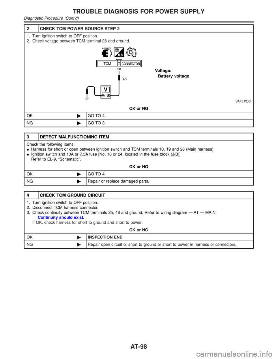
2 CHECK TCM POWER SOURCE STEP 2
1. Turn ignition switch to OFF position.
2. Check voltage between TCM terminal 28 and ground.
SAT612JC
OK or NG
OK©GO TO 4.
NG©GO TO 3.
3 DETECT MALFUNCTIONING ITEM
Check the following items:
IHarness for short or open between ignition switch and TCM terminals 10, 19 and 28 (Main harness)
IIgnition switch and 10A or 7.5A fuse [No. 18 or 24, located in the fuse block (J/B)]
Refer to EL-9, ªSchematicº.
OK or NG
OK©GO TO 4.
NG©Repair or replace damaged parts.
4 CHECK TCM GROUND CIRCUIT
1. Turn ignition switch to OFF position.
2. Disconnect TCM harness connector.
3. Check continuity between TCM terminals 25, 48 and ground. Refer to wiring diagram Ð AT Ð MAIN.
Continuity should exist.
If OK, check harness for short to ground and short to power.
OK or NG
OK©INSPECTION END
NG©Repair open circuit or short to ground or short to power in harness or connectors.
TROUBLE DIAGNOSIS FOR POWER SUPPLY
Diagnostic Procedure (Cont'd)
AT-98