turn signal INFINITI QX4 2001 Factory Owner's Manual
[x] Cancel search | Manufacturer: INFINITI, Model Year: 2001, Model line: QX4, Model: INFINITI QX4 2001Pages: 2395, PDF Size: 43.2 MB
Page 218 of 2395

SAT574J
DescriptionNBAT0215The TCM consists of a microcomputer and connectors for signal
input and output and for power supply. The unit controls the A/T.
ON BOARD DIAGNOSIS LOGICNBAT0215S01
Diagnostic trouble code Malfunction is detected when ... Check item (Possible cause)
: CONT UNIT (EEP ROM)TCM memory (EEP ROM) is malfunc-
tioning.TCM
SAT014K
SAT971J
DIAGNOSTIC TROUBLE CODE (DTC) CONFIRMATION
PROCEDURE
NBAT0215S02NOTE:
If ªDIAGNOSTIC TROUBLE CODE CONFIRMATION PROCE-
DUREº has been previously conducted, always turn ignition
switch ªOFFº and wait at least 5 seconds before conducting
the next test.
With CONSULT-II
1) Turn ignition switch ªONº and select ªDATA MONITORº mode
for A/T with CONSULT-II.
2) Start engine.
3) Run engine for at least 2 seconds at idle speed.
GI
MA
EM
LC
EC
FE
TF
PD
AX
SU
BR
ST
RS
BT
HA
SC
EL
IDX
DTC CONTROL UNIT (EEP ROM)
Description
AT-213
Page 256 of 2395

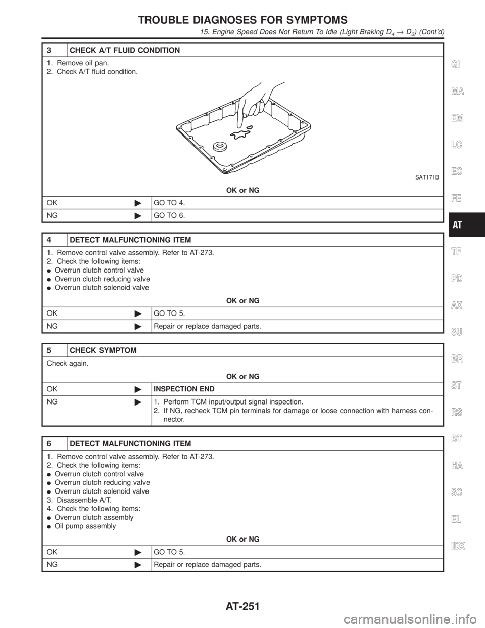
3 CHECK A/T FLUID CONDITION
1. Remove oil pan.
2. Check A/T fluid condition.
SAT171B
OK or NG
OK©GO TO 4.
NG©GO TO 6.
4 DETECT MALFUNCTIONING ITEM
1. Remove control valve assembly. Refer to AT-273.
2. Check the following items:
IOverrun clutch control valve
IOverrun clutch reducing valve
IOverrun clutch solenoid valve
OK or NG
OK©GO TO 5.
NG©Repair or replace damaged parts.
5 CHECK SYMPTOM
Check again.
OK or NG
OK©INSPECTION END
NG©1. Perform TCM input/output signal inspection.
2. If NG, recheck TCM pin terminals for damage or loose connection with harness con-
nector.
6 DETECT MALFUNCTIONING ITEM
1. Remove control valve assembly. Refer to AT-273.
2. Check the following items:
IOverrun clutch control valve
IOverrun clutch reducing valve
IOverrun clutch solenoid valve
3. Disassemble A/T.
4. Check the following items:
IOverrun clutch assembly
IOil pump assembly
OK or NG
OK©GO TO 5.
NG©Repair or replace damaged parts.
GI
MA
EM
LC
EC
FE
TF
PD
AX
SU
BR
ST
RS
BT
HA
SC
EL
IDX
TROUBLE DIAGNOSES FOR SYMPTOMS
15. Engine Speed Does Not Return To Idle (Light Braking D4®D3) (Cont'd)
AT-251
Page 263 of 2395

DIAGNOSTIC PROCEDURE=NBAT0204S03NOTE:
The diagnostic procedure includes inspections for the overdrive
control and throttle position switch circuits.
1 INSPECTION START
Do you have CONSULT-II?
YesorNo
Yes (With CONSULT-II)©GO TO 2.
No (Without CONSULT-
II)©GO TO 3.
2 CHECK PNP SWITCH CIRCUIT (With CONSULT-II)
With CONSULT-II
1. Turn ignition switch to ªONº position.
(Do not start engine.)
2. Select ªTCM INPUT SIGNALSº in ªDATA MONITORº mode for ªA/Tº with CONSULT-II.
3. Read out ªPº, ªRº, ªNº, ªDº, ª2º and ª1º position switches moving selector lever to each position. Check the signal of the
selector lever position is indicated properly.
SAT643J
OK or NG
OK©GO TO 5.
NG©GO TO 4.
TROUBLE DIAGNOSES FOR SYMPTOMS
21. TCM Self-diagnosis Does Not Activate (PNP, Overdrive Control and Throttle Position Switches Circuit Checks) (Cont'd)
AT-258
Page 265 of 2395

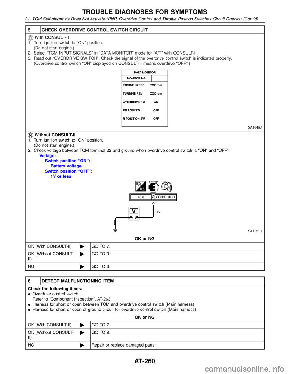
5 CHECK OVERDRIVE CONTROL SWITCH CIRCUIT
With CONSULT-II
1. Turn ignition switch to ªONº position.
(Do not start engine.)
2. Select ªTCM INPUT SIGNALSº in ªDATA MONITORº mode for ªA/Tº with CONSULT-II.
3. Read out ªOVERDRIVE SWITCHº. Check the signal of the overdrive control switch is indicated properly.
(Overdrive control switch ªONº displayed on CONSULT-II means overdrive ªOFFº.)
SAT645J
Without CONSULT-II
1. Turn ignition switch to ªONº position.
(Do not start engine.)
2. Check voltage between TCM terminal 22 and ground when overdrive control switch is ªONº and ªOFFº.
Voltage:
Switch position ªONº:
Battery voltage
Switch position ªOFFº:
1V or less
SAT531J
OK or NG
OK (With CONSULT-II)©GO TO 7.
OK (Without CONSULT-
II)©GO TO 9.
NG©GO TO 6.
6 DETECT MALFUNCTIONING ITEM
Check the following items:
IOverdrive control switch
Refer to ªComponent Inspectionº, AT-263.
IHarness for short or open between TCM and overdrive control switch (Main harness)
IHarness for short or open of ground circuit for overdrive control switch (Main harness)
OK or NG
OK (With CONSULT-II)©GO TO 7.
OK (Without CONSULT-
II)©GO TO 9.
NG©Repair or replace damaged parts.
TROUBLE DIAGNOSES FOR SYMPTOMS
21. TCM Self-diagnosis Does Not Activate (PNP, Overdrive Control and Throttle Position Switches Circuit Checks) (Cont'd)
AT-260
Page 266 of 2395

7 CHECK THROTTLE POSITION SWITCH CIRCUIT (With CONSULT-II)
With CONSULT-II
1. Turn ignition switch to ªONº position.
(Do not start engine.)
2. Select ªTCM INPUT SIGNALSº in ªDATA MONITORº mode for ªA/Tº with CONSULT-II.
3. Apply vacuum to the throttle opener, then check the following. Refer to steps 1 and 2 of ªPreparationº, ªTCM SELF-
DIAGNOSTIC PROCEDURE (No Tools)º, AT-46.
4. Read out ªCLOSED THL/SWº and ªW/O THRL/P-SWº depressing and releasing accelerator pedal.
Check the signal of throttle position switch is indicated properly.
MTBL0011
SAT646J
OK or NG
OK©GO TO 10.
NG©GO TO 8.
8 DETECT MALFUNCTIONING ITEM
Check the following items:
IThrottle position switch
Refer to ªComponent Inspectionº, AT-264.
IHarness for short or open between ignition switch and throttle position switch (Main harness)
IHarness for short or open between throttle position switch and TCM (Main harness)
OK or NG
OK©GO TO 10.
NG©Repair or replace damaged parts.
GI
MA
EM
LC
EC
FE
TF
PD
AX
SU
BR
ST
RS
BT
HA
SC
EL
IDX
TROUBLE DIAGNOSES FOR SYMPTOMS
21. TCM Self-diagnosis Does Not Activate (PNP, Overdrive Control and Throttle Position Switches Circuit Checks) (Cont'd)
AT-261
Page 267 of 2395

9 CHECK THROTTLE POSITION SWITCH CIRCUIT (Without CONSULT-II)
Without CONSULT-II
1. Turn ignition switch to ªONº position.
(Do not start engine.)
2. Check voltage between TCM terminals 16, 17 and ground while depressing, and releasing accelerator pedal slowly.
(after warming up engine)
[Refer to ªPreparationº, ªTCM SELF-DIAGNOSTIC PROCEDURE (No Tools)º, AT-46.]
MTBL0519
SAT526J
OK or NG
OK©GO TO 10.
NG©GO TO 8.
10 CHECK DTC
Perform Diagnostic procedure, AT-258.
OK or NG
OK©INSPECTION END
NG©GO TO 11.
11 CHECK TCM INSPECTION
1. Perform TCM input/output signal inspection.
2. If NG, recheck TCM pin terminals for damage or loose connection with harness connector.
OK or NG
OK©INSPECTION END
NG©Repair or replace damaged parts.
TROUBLE DIAGNOSES FOR SYMPTOMS
21. TCM Self-diagnosis Does Not Activate (PNP, Overdrive Control and Throttle Position Switches Circuit Checks) (Cont'd)
AT-262
Page 273 of 2395
![INFINITI QX4 2001 Factory Owners Manual 4 DETECT MALFUNCTIONING ITEM
Check the following items:
1. Harness for short or open between ignition switch and A/T device harness terminal 5
2. 7.5A fuse [No. 11, located in the fuse block (J/B)]
3. INFINITI QX4 2001 Factory Owners Manual 4 DETECT MALFUNCTIONING ITEM
Check the following items:
1. Harness for short or open between ignition switch and A/T device harness terminal 5
2. 7.5A fuse [No. 11, located in the fuse block (J/B)]
3.](/img/42/57027/w960_57027-272.png)
4 DETECT MALFUNCTIONING ITEM
Check the following items:
1. Harness for short or open between ignition switch and A/T device harness terminal 5
2. 7.5A fuse [No. 11, located in the fuse block (J/B)]
3. Ignition switch (Refer to EL-9, ªSchematicº.)
OK or NG
OK©GO TO 5.
NG©Repair or replace damaged parts.
5 CHECK INPUT SIGNAL A/T DEVICE
Turn ignition switch to OFF position.
ICheck voltage between A/T device harness terminal 7 and ground.
SAT179K
OK or NG
OK©GO TO 7.
NG©GO TO 6.
6 DETECT MALFUNCTIONING ITEM
Check the following items:
1. Harness for short or open between battery and stop lamp switch harness connector 1
2. Harness for short or open between stop lamp switch harness connector 2 and A/T device harness connector 7
3. Diode
4. 10A fuse [No. 14, located in the fuse block (J/B)]
5. Stop lamp switch
a. Check continuity between terminals 1 and 2.
SAT146K
Check stop lamp switch after adjusting brake pedal Ð refer to BR-14, ªAdjustmentº.
OK or NG
OK©GO TO 7.
NG©Repair or replace damaged parts.
A/T SHIFT LOCK SYSTEM
Diagnostic Procedure (Cont'd)
AT-268
Page 275 of 2395

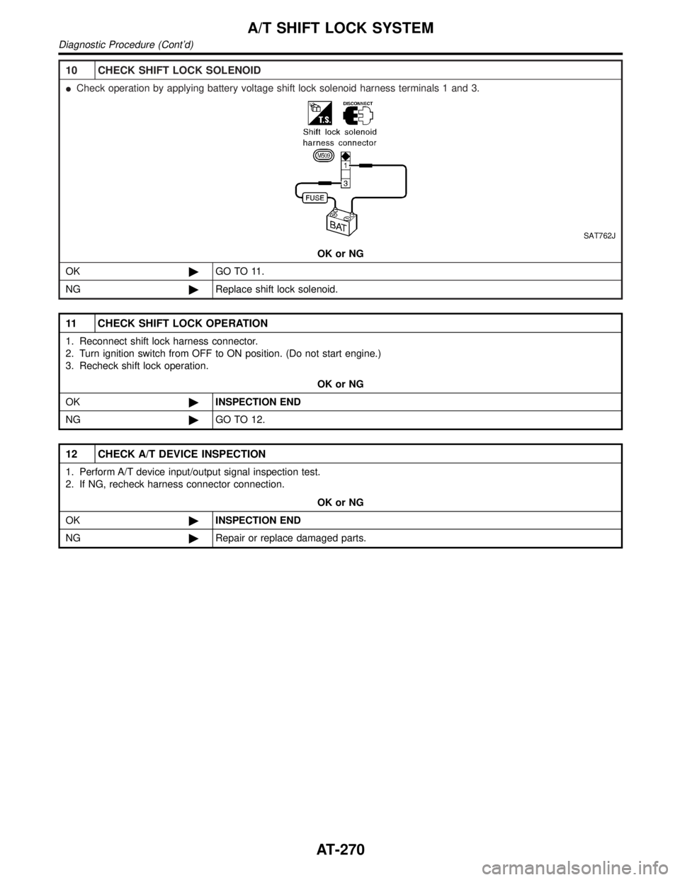
10 CHECK SHIFT LOCK SOLENOID
ICheck operation by applying battery voltage shift lock solenoid harness terminals 1 and 3.
SAT762J
OK or NG
OK©GO TO 11.
NG©Replace shift lock solenoid.
11 CHECK SHIFT LOCK OPERATION
1. Reconnect shift lock harness connector.
2. Turn ignition switch from OFF to ON position. (Do not start engine.)
3. Recheck shift lock operation.
OK or NG
OK©INSPECTION END
NG©GO TO 12.
12 CHECK A/T DEVICE INSPECTION
1. Perform A/T device input/output signal inspection test.
2. If NG, recheck harness connector connection.
OK or NG
OK©INSPECTION END
NG©Repair or replace damaged parts.
A/T SHIFT LOCK SYSTEM
Diagnostic Procedure (Cont'd)
AT-270
Page 423 of 2395

This component controls the hydraulic circuit and increases, holds
or decreases hydraulic pressure to all or individual wheels. The
ABS actuator and electric unit is serviced as an assembly.
ABS Actuator OperationNBBR0091S0301
Inlet solenoid
valveOutlet solenoid
valve
Normal brake operation OFF (Open) OFF (Closed)Master cylinder brake fluid pressure is directly
transmitted to caliper via the inlet solenoid valve.
ABS operationPressure hold ON (Closed) OFF (Closed)Hydraulic circuit is shut off to hold the caliper
brake fluid pressure.
Pressure
decreaseON (Closed) ON (Open)Caliper brake fluid is sent to reservoir via the out-
let solenoid valve. Then it is pushed up to the
master cylinder by pump.
Pressure increase OFF (Open) OFF (Closed)Master cylinder brake fluid pressure is transmitted
to caliper.
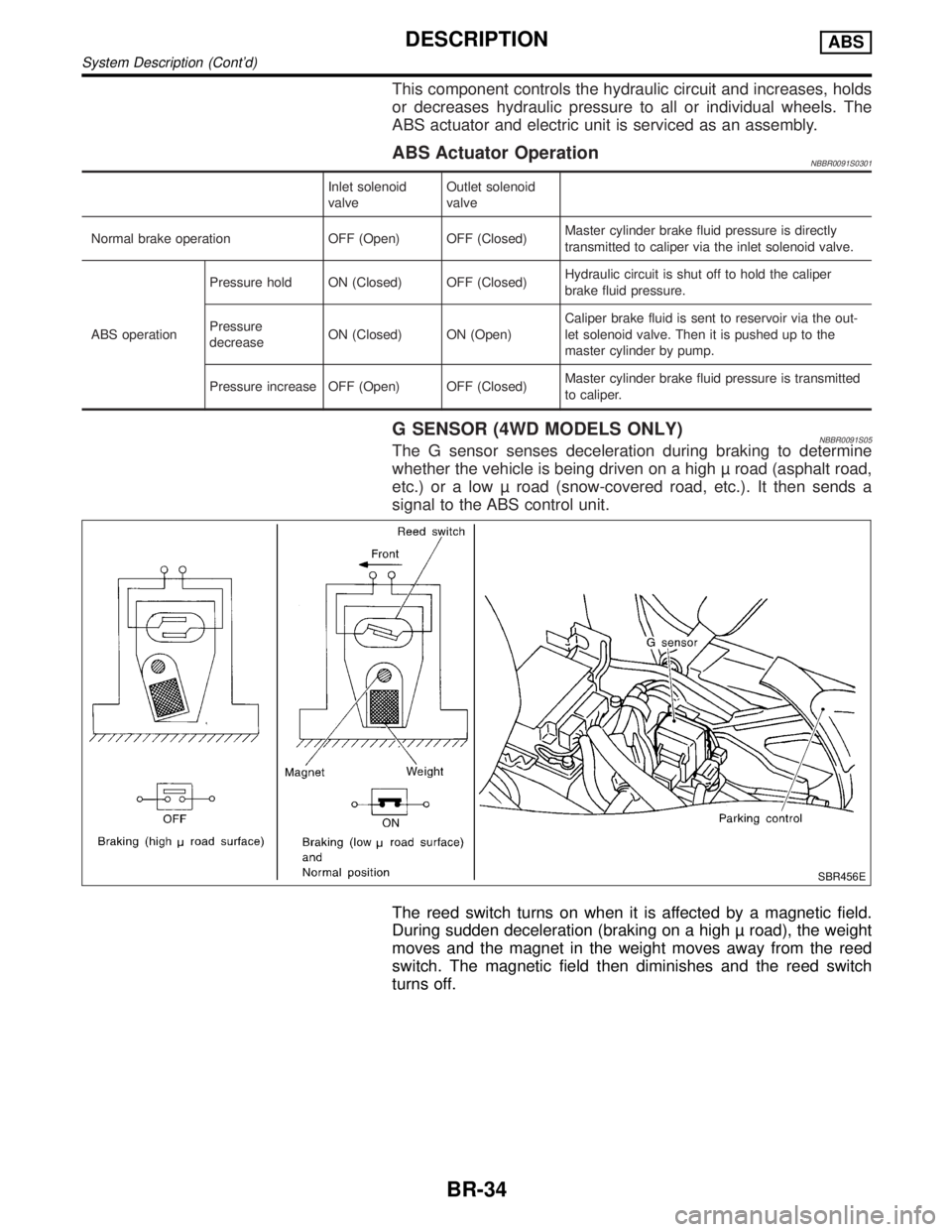
G SENSOR (4WD MODELS ONLY)NBBR0091S05The G sensor senses deceleration during braking to determine
whether the vehicle is being driven on a high road (asphalt road,
etc.) or a low road (snow-covered road, etc.). It then sends a
signal to the ABS control unit.
SBR456E
The reed switch turns on when it is affected by a magnetic field.
During sudden deceleration (braking on a high road), the weight
moves and the magnet in the weight moves away from the reed
switch. The magnetic field then diminishes and the reed switch
turns off.
DESCRIPTIONABS
System Description (Cont'd)
BR-34
Page 434 of 2395
![INFINITI QX4 2001 Factory Owners Manual SELF-DIAGNOSTIC RESULTS MODENBBR0097S02
Diagnostic item Diagnostic item is detected when ... Reference Page
FR RH SENSOR*1
[OPEN]ICircuit for front right wheel sensor is open.
(An abnormally high inpu INFINITI QX4 2001 Factory Owners Manual SELF-DIAGNOSTIC RESULTS MODENBBR0097S02
Diagnostic item Diagnostic item is detected when ... Reference Page
FR RH SENSOR*1
[OPEN]ICircuit for front right wheel sensor is open.
(An abnormally high inpu](/img/42/57027/w960_57027-433.png)
SELF-DIAGNOSTIC RESULTS MODENBBR0097S02
Diagnostic item Diagnostic item is detected when ... Reference Page
FR RH SENSOR*1
[OPEN]ICircuit for front right wheel sensor is open.
(An abnormally high input voltage is entered.)BR-56
FR LH SENSOR*1
[OPEN]ICircuit for front left wheel sensor is open.
(An abnormally high input voltage is entered.)BR-56
RR RH SENSOR*1
[OPEN]ICircuit for rear right sensor is open.
(An abnormally high input voltage is entered.)BR-56
RR LH SENSOR*1
[OPEN]ICircuit for rear left sensor is open.
(An abnormally high input voltage is entered.)BR-56
FR RH SENSOR*1
[SHORT]ICircuit for front right wheel sensor is shorted.
(An abnormally low input voltage is entered.)BR-56
FR LH SENSOR*1
[SHORT]ICircuit for front left wheel sensor is shorted.
(An abnormally low input voltage is entered.)BR-56
RR RH SENSOR*1
[SHORT]ICircuit for rear right sensor is shorted.
(An abnormally low input voltage is entered.)BR-56
RR LH SENSOR*1
[SHORT]ICircuit for rear left sensor is shorted.
(An abnormally low input voltage is entered.)BR-56
ABS SENSOR*1
[ABNORMAL SIGNAL]ITeeth damage on sensor rotor or improper installation of wheel sensor.
(Abnormal wheel sensor signal is entered.)BR-56
FR RH IN ABS SOL
[OPEN, SHORT]ICircuit for front right inlet solenoid valve is open.
(An abnormally low output voltage is entered.)BR-59
FR LH IN ABS SOL
[OPEN, SHORT]ICircuit for front left inlet solenoid valve is open.
(An abnormally low output voltage is entered.)BR-59
FR RH OUT ABS SOL
[OPEN, SHORT]ICircuit for front right outlet solenoid valve is open.
(An abnormally low output voltage is entered.)BR-59
FR LH OUT ABS SOL
[OPEN, SHORT]ICircuit for front left outlet solenoid valve is open.
(An abnormally low output voltage is entered.)BR-59
RR IN ABS SOL
[OPEN, SHORT]ICircuit for rear inlet solenoid valve is shorted.
(An abnormally high output voltage is entered.)BR-59
RR OUT ABS SOL
[OPEN, SHORT]ICircuit for rear out solenoid valve is shorted.
(An abnormally high output voltage is entered.)BR-59
ABS ACTUATOR RELAY
[ABNORMAL]IActuator solenoid valve relay is ON, even if control unit sends off signal.
IActuator solenoid valve relay is OFF, even if control unit sends on signal.BR-59
ABS MOTOR RELAY
[ABNORMAL]ICircuit for ABS motor relay is open or shorted.
ICircuit for actuator motor is open or shorted.
IActuator motor relay is stuck.BR-61
BATTERY VOLT
[VB-LOW]IPower source voltage supplied to ABS control unit is abnormally low.
BR-63
CONTROL UNITIFunction of calculation in ABS control unit has failed. BR-68
G SENSOR*2
[ABNORMAL]IG sensor circuit is open or shorted.
BR-65
*1: If one or more wheels spin on a rough or slippery road for 40 seconds or more, the ABS warning lamp will illuminate. This does not
indicate a malfunction. Only in the case of the short-circuit (Code Nos. 26, 22, 32 and 36), after repair the ABS warning lamp also illu-
minates when the ignition switch is turned ON. In this case, drive the vehicle at speeds greater than 30 km/h (19 MPH) for approxi-
mately 1 minute as specified in ªSELF-DIAGNOSIS PROCEDUREº, BR-41. Check to ensure that the ABS warning lamp goes out while
the vehicle is being driven.
*2: 4WD models onlyGI
MA
EM
LC
EC
FE
AT
TF
PD
AX
SU
ST
RS
BT
HA
SC
EL
IDX
ON BOARD DIAGNOSTIC SYSTEM DESCRIPTIONABS
CONSULT-II Inspection Procedure (Cont'd)
BR-45