check engine INFINITI QX4 2001 Factory Service Manual
[x] Cancel search | Manufacturer: INFINITI, Model Year: 2001, Model line: QX4, Model: INFINITI QX4 2001Pages: 2395, PDF Size: 43.2 MB
Page 1693 of 2395
SEM653F
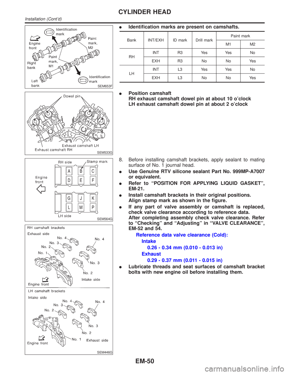
IIdentification marks are present on camshafts.
Bank INT/EXH ID mark Drill markPaint mark
M1 M2
RHINT R3 Yes Yes No
EXH R3 No No Yes
LHINT L3 Yes Yes No
EXH L3 No No Yes
SEM533G
IPosition camshaft
RH exhaust camshaft dowel pin at about 10 o'clock
LH exhaust camshaft dowel pin at about 2 o'clock
SEM564G
SEM446G
8. Before installing camshaft brackets, apply sealant to mating
surface of No. 1 journal head.
IUse Genuine RTV silicone sealant Part No. 999MP-A7007
or equivalent.
IRefer to ªPOSITION FOR APPLYING LIQUID GASKETº,
EM-21.
IInstall camshaft brackets in their original positions.
Align stamp mark as shown in the figure.
IIf any part of valve assembly or camshaft is replaced,
check valve clearance according to reference data.
After completing assembly check valve clearance. Refer
to ªCheckingº and ªAdjustingº in ªVALVE CLEARANCEº,
EM-52 and 54.
Reference data valve clearance (Cold):
Intake
0.26 - 0.34 mm (0.010 - 0.013 in)
Exhaust
0.29 - 0.37 mm (0.011 - 0.015 in)
ILubricate threads and seat surfaces of camshaft bracket
bolts with new engine oil before installing them.
CYLINDER HEAD
Installation (Cont'd)
EM-50
Page 1695 of 2395
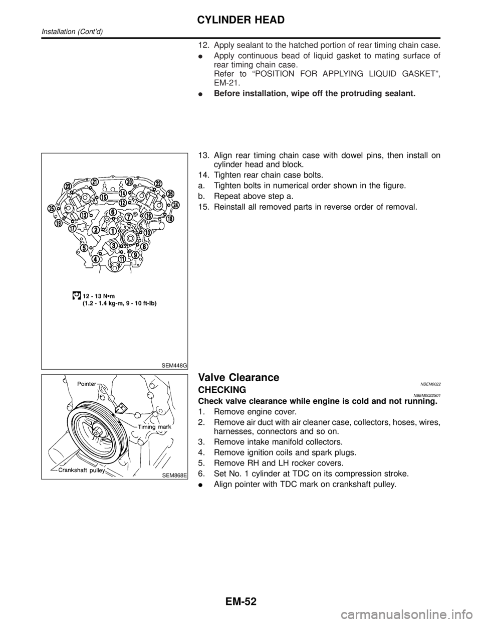
12. Apply sealant to the hatched portion of rear timing chain case.
IApply continuous bead of liquid gasket to mating surface of
rear timing chain case.
Refer to ªPOSITION FOR APPLYING LIQUID GASKETº,
EM-21.
IBefore installation, wipe off the protruding sealant.
SEM448G
13. Align rear timing chain case with dowel pins, then install on
cylinder head and block.
14. Tighten rear chain case bolts.
a. Tighten bolts in numerical order shown in the figure.
b. Repeat above step a.
15. Reinstall all removed parts in reverse order of removal.
SEM868E
Valve ClearanceNBEM0022CHECKINGNBEM0022S01Check valve clearance while engine is cold and not running.
1. Remove engine cover.
2. Remove air duct with air cleaner case, collectors, hoses, wires,
harnesses, connectors and so on.
3. Remove intake manifold collectors.
4. Remove ignition coils and spark plugs.
5. Remove RH and LH rocker covers.
6. Set No. 1 cylinder at TDC on its compression stroke.
IAlign pointer with TDC mark on crankshaft pulley.
CYLINDER HEAD
Installation (Cont'd)
EM-52
Page 1697 of 2395
SEM894E
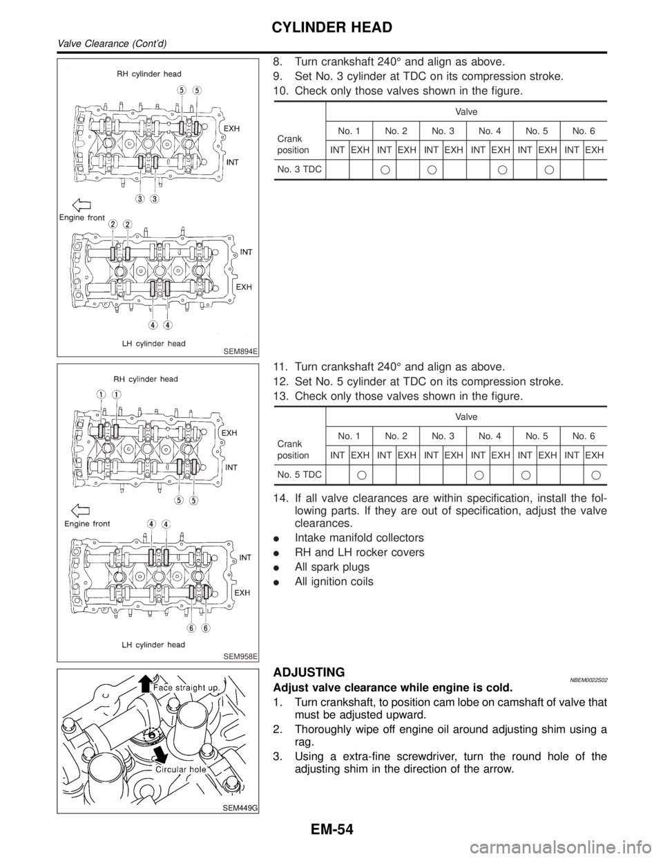
8. Turn crankshaft 240É and align as above.
9. Set No. 3 cylinder at TDC on its compression stroke.
10. Check only those valves shown in the figure.
Crank
positionValve
No. 1 No. 2 No. 3 No. 4 No. 5 No. 6
INT EXH INT EXH INT EXH INT EXH INT EXH INT EXH
No. 3 TDCqq qq
SEM958E
11. Turn crankshaft 240É and align as above.
12. Set No. 5 cylinder at TDC on its compression stroke.
13. Check only those valves shown in the figure.
Crank
positionValve
No. 1 No. 2 No. 3 No. 4 No. 5 No. 6
INT EXH INT EXH INT EXH INT EXH INT EXH INT EXH
No. 5 TDCqqqq
14. If all valve clearances are within specification, install the fol-
lowing parts. If they are out of specification, adjust the valve
clearances.
IIntake manifold collectors
IRH and LH rocker covers
IAll spark plugs
IAll ignition coils
SEM449G
ADJUSTINGNBEM0022S02Adjust valve clearance while engine is cold.
1. Turn crankshaft, to position cam lobe on camshaft of valve that
must be adjusted upward.
2. Thoroughly wipe off engine oil around adjusting shim using a
rag.
3. Using a extra-fine screwdriver, turn the round hole of the
adjusting shim in the direction of the arrow.
CYLINDER HEAD
Valve Clearance (Cont'd)
EM-54
Page 1708 of 2395
SEM038F
SEM003F
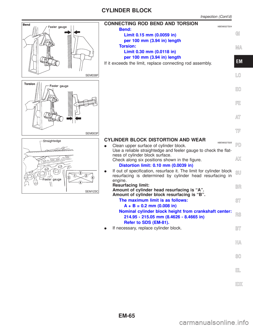
CONNECTING ROD BEND AND TORSIONNBEM0027S04Bend:
Limit 0.15 mm (0.0059 in)
per 100 mm (3.94 in) length
Torsion:
Limit 0.30 mm (0.0118 in)
per 100 mm (3.94 in) length
If it exceeds the limit, replace connecting rod assembly.
SEM123C
CYLINDER BLOCK DISTORTION AND WEARNBEM0027S05IClean upper surface of cylinder block.
Use a reliable straightedge and feeler gauge to check the flat-
ness of cylinder block surface.
Check along six positions shown in the figure.
Distortion limit: 0.10 mm (0.0039 in)
IIf out of specification, resurface it. The limit for cylinder block
resurfacing is determined by cylinder head resurfacing in
engine.
Resurfacing limit:
Amount of cylinder head resurfacing is ªAº.
Amount of cylinder block resurfacing is ªBº.
The maximum limit is as follows:
A + B = 0.2 mm (0.008 in)
Nominal cylinder block height from crankshaft center:
214.95 - 215.05 mm (8.4626 - 8.4665 in)
Refer to SDS (EM-81).
IIf necessary, replace cylinder block.
GI
MA
LC
EC
FE
AT
TF
PD
AX
SU
BR
ST
RS
BT
HA
SC
EL
IDX
CYLINDER BLOCK
Inspection (Cont'd)
EM-65
Page 1733 of 2395
Removal and InstallationNBFE0004WARNING:
When replacing fuel line parts, be sure to observe the follow-
ing:
IPut a ªCAUTION: INFLAMMABLEº sign in workshop.
IDo not smoke while servicing fuel system. Keep open
flames and sparks away from work area.
IBe sure to furnish the workshop with a CO
2fire extin-
guisher.
CAUTION:
IBefore removing fuel line parts, carry out the following
procedures:
a) Put drained fuel in an explosion-proof container and put
lid on securely.
b) Release fuel pressure from fuel line. Refer to MA-16,
ªChanging Fuel Filterº.
c) Disconnect battery ground cable.
IAlways replace O-ring with new ones.
IDo not kink or twist hose and tube when they are installed.
IDo not tighten hose clamps excessively to avoid damag-
ing hoses.
IWhen installing fuel check valve, be careful of its desig-
nated direction. Refer to EC-32, ªEVAPORATIVE EMIS-
SION SYSTEMº.
IAfter installation, run engine and check for fuel leaks at
connections.
FUEL SYSTEM
Removal and Installation
FE-4
Page 1737 of 2395
Removal and InstallationNBFE0005CAUTION:
IAlways replace exhaust gaskets with new ones when reassembling.
IWith engine running, check all tube connections for exhaust gas leaks, and entire system for
unusual noises.
ICheck to ensure that mounting brackets and mounting insulators are installed properly and free
from undue stress. Improper installation could result in excessive noise or vibration.
IDiscard any heated oxygen sensor which has been dropped from a height of more than 0.5 m (19.7
in) onto a hard surface such as a concrete floor; use a new one.
IBefore installing new oxygen sensor, clean exhaust system threads using Oxygen Sensor Thread
Cleaner tool J-43897-18 of J-43897-12 and approved anti-seize lubricant.
IDo not overtorque the oxygen sensor. Doing so may cause damage to the oxygen sensor, result-
ing in the MIL coming on.
EXHAUST SYSTEM
Removal and Installation
FE-8
Page 1746 of 2395
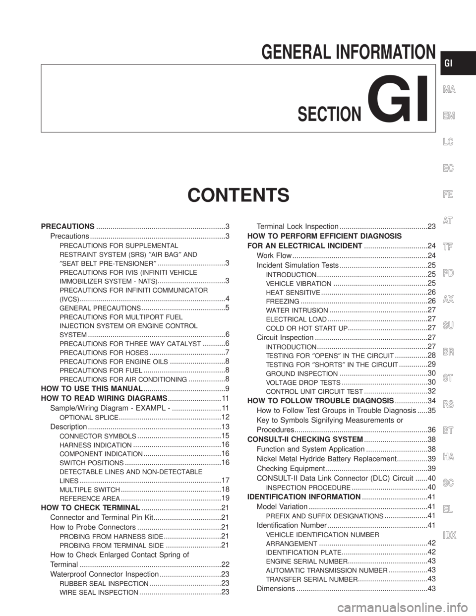
GENERAL INFORMATION
SECTION
GI
CONTENTS
PRECAUTIONS...............................................................3
Precautions ..................................................................3
PRECAUTIONS FOR SUPPLEMENTAL
RESTRAINT SYSTEM (SRS)²AIR BAG²AND
²SEAT BELT PRE-TENSIONER²
.................................3
PRECAUTIONS FOR IVIS (INFINITI VEHICLE
IMMOBILIZER SYSTEM - NATS)
.................................3
PRECAUTIONS FOR INFINITI COMMUNICATOR
(IVCS)
.......................................................................4
GENERAL PRECAUTIONS.........................................5
PRECAUTIONS FOR MULTIPORT FUEL
INJECTION SYSTEM OR ENGINE CONTROL
SYSTEM
...................................................................6
PRECAUTIONS FOR THREE WAY CATALYST...........6
PRECAUTIONS FOR HOSES.....................................7
PRECAUTIONS FOR ENGINE OILS...........................8
PRECAUTIONS FOR FUEL........................................8
PRECAUTIONS FOR AIR CONDITIONING..................8
HOW TO USE THIS MANUAL........................................9
HOW TO READ WIRING DIAGRAMS.......................... 11
Sample/Wiring Diagram - EXAMPL - ........................ 11
OPTIONAL SPLICE..................................................12
Description .................................................................13
CONNECTOR SYMBOLS.........................................15
HARNESS INDICATION...........................................16
COMPONENT INDICATION......................................16
SWITCH POSITIONS...............................................16
DETECTABLE LINES AND NON-DETECTABLE
LINES
.....................................................................17
MULTIPLE SWITCH.................................................18
REFERENCE AREA.................................................19
HOW TO CHECK TERMINAL.......................................21
Connector and Terminal Pin Kit.................................21
How to Probe Connectors .........................................21
PROBING FROM HARNESS SIDE............................21
PROBING FROM TERMINAL SIDE...........................21
How to Check Enlarged Contact Spring of
Terminal .....................................................................22
Waterproof Connector Inspection ..............................23
RUBBER SEAL INSPECTION...................................23
WIRE SEAL INSPECTION........................................23Terminal Lock Inspection ...........................................23
HOW TO PERFORM EFFICIENT DIAGNOSIS
FOR AN ELECTRICAL INCIDENT...............................24
Work Flow ..................................................................24
Incident Simulation Tests ...........................................25
INTRODUCTION......................................................25
VEHICLE VIBRATION..............................................25
HEAT SENSITIVE....................................................26
FREEZING..............................................................26
WATER INTRUSION................................................27
ELECTRICAL LOAD.................................................27
COLD OR HOT START UP.......................................27
Circuit Inspection .......................................................27
INTRODUCTION......................................................27
TESTING FOR²OPENS²IN THE CIRCUIT................28
TESTING FOR²SHORTS²IN THE CIRCUIT..............29
GROUND INSPECTION...........................................30
VOLTAGE DROP TESTS..........................................30
CONTROL UNIT CIRCUIT TEST...............................32
HOW TO FOLLOW TROUBLE DIAGNOSIS................34
How to Follow Test Groups in Trouble Diagnosis .....35
Key to Symbols Signifying Measurements or
Procedures.................................................................36
CONSULT-II CHECKING SYSTEM...............................38
Function and System Application ..............................38
Nickel Metal Hydride Battery Replacement...............39
Checking Equipment..................................................39
CONSULT-II Data Link Connector (DLC) Circuit ......40
INSPECTION PROCEDURE.....................................40
IDENTIFICATION INFORMATION................................41
Model Variation ..........................................................41
PREFIX AND SUFFIX DESIGNATIONS.....................41
Identification Number .................................................41
VEHICLE IDENTIFICATION NUMBER
ARRANGEMENT
.....................................................42
IDENTIFICATION PLATE..........................................42
ENGINE SERIAL NUMBER.......................................43
AUTOMATIC TRANSMISSION NUMBER...................43
TRANSFER SERIAL NUMBER..................................43
Dimensions ................................................................43
MA
EM
LC
EC
FE
AT
TF
PD
AX
SU
BR
ST
RS
BT
HA
SC
EL
IDX
Page 1751 of 2395
IClean all disassembled parts in the designated liquid or solvent
prior to inspection or assembly.
IReplace oil seals, gaskets, packings, O-rings, locking washers,
cotter pins, self-locking nuts, etc. with new ones.
IReplace inner and outer races of tapered roller bearings and
needle bearings as a set.
IArrange the disassembled parts in accordance with their
assembled locations and sequence.
IDo not touch the terminals of electrical components which use
microcomputers (such as ECMs).
Static electricity may damage internal electronic components.
IAfter disconnecting vacuum or air hoses, attach a tag to indi-
cate the proper connection.
IUse only the fluids and lubricants specified in this manual.
IUse approved bonding agent, sealants or their equivalents
when required.
IUse tools and recommended special tools where specified for
safe and efficient service repairs.
IWhen repairing the fuel, oil, water, vacuum or exhaust
systems, check all affected lines for leaks.
IDispose of drained oil or the solvent used for cleaning parts in
an appropriate manner.
WARNING:
To prevent ECM from storing the diagnostic trouble codes, do
not carelessly disconnect the harness connectors which are
related to the engine control system and TCM (Transmission
Control Module) system. The connectors should be discon-
nected only when working according to the WORK FLOW of
TROUBLE DIAGNOSES in EC and AT sections.
SGI787
PRECAUTIONS FOR MULTIPORT FUEL INJECTION
SYSTEM OR ENGINE CONTROL SYSTEM
NBGI0001S03IBefore connecting or disconnecting any harness connector for
the multiport fuel injection system or ECM (Engine Control
Module):
Turn ignition switch to OFF position.
Disconnect negative battery terminal.
Otherwise, there may be damage to ECM.
IBefore disconnecting pressurized fuel line from fuel pump to
injectors, be sure to release fuel pressure.
IBe careful not to jar components such as ECM and mass air
flow sensor.
PRECAUTIONS FOR THREE WAY CATALYSTNBGI0001S04If a large amount of unburned fuel flows into the catalyst, the cata-
lyst temperature will be excessively high. To prevent this, follow the
instructions below:
IUse unleaded gasoline only. Leaded gasoline will seriously
damage the three way catalyst.
IWhen checking for ignition spark or measuring engine
compression, make tests quickly and only when necessary.
IDo not run engine when the fuel tank level is low, otherwise the
engine may misfire causing damage to the catalyst.
PRECAUTIONS
Precautions (Cont'd)
GI-6
Page 1753 of 2395
PRECAUTIONS FOR ENGINE OILSNBGI0001S05Prolonged and repeated contact with used engine oil may cause
skin cancer. Try to avoid direct skin contact with used oil.
If skin contact is made, wash thoroughly with soap or hand cleaner
as soon as possible.
Health Protection PrecautionsNBGI0001S0501IAvoid prolonged and repeated contact with oils, particularly
used engine oils.
IWear protective clothing, including impervious gloves where
practicable.
IDo not put oily rags in pockets.
IAvoid contaminating clothes, particularly underpants, with oil.
IHeavily soiled clothing and oil-impregnated footwear should
not be worn. Overalls must be cleaned regularly.
IFirst Aid treatment should be obtained immediately for open
cuts and wounds.
IUse barrier creams, applying them before each work period, to
help the removal of oil from the skin.
IWash with soap and water to ensure all oil is removed (skin
cleansers and nail brushes will help). Preparations containing
lanolin replace the natural skin oils which have been removed.
IDo not use gasoline, kerosine, diesel fuel, gas oil, thinners or
solvents for cleaning skin.
IIf skin disorders develop, obtain medical advice without delay.
IWhere practicable, degrease components prior to handling.
IWhere there is a risk of eye contact, eye protection should be
worn, for example, chemical goggles or face shields; in addi-
tion an eye wash facility should be provided.
Environmental Protection PrecautionsNBGI0001S0502Burning used engine oil in small space heaters or boilers can be
recommended only for units of approved design. The heating sys-
tem must meet the requirements of HM Inspectorate of Pollution for
small burners of less than 0.4 MW. If in doubt check with the
appropriate local authority and/or manufacturer of the approved
appliance.
Dispose of used oil and used oil filters through authorized waste
disposal contractors to licensed waste disposal sites, or to the
waste oil reclamation trade. If in doubt, contact the local authority
for advice on disposal facilities.
It is illegal to pour used oil on to the ground, down sewers or drains,
or into water courses.
The regulations concerning pollution vary between regions.
PRECAUTIONS FOR FUELNBGI0001S06Use unleaded gasoline with an octane rating of at least 87 AKI
(Anti-Knock Index) number (research octane number 91).
CAUTION:
Do not use leaded gasoline. Using leaded gasoline will dam-
age the three way catalyst.
Using a fuel other than that specified could adversely affect
the emission control devices and systems, and could also
affect the warranty coverage validity.
PRECAUTIONS FOR AIR CONDITIONINGNBGI0001S07Use an approved refrigerant recovery unit any time the air condi-
tioning system must be discharged. Refer to HA-144, ªHFC-134a
(R-134a) Service Procedureº for specific instructions.
PRECAUTIONS
Precautions (Cont'd)
GI-8
Page 1755 of 2395
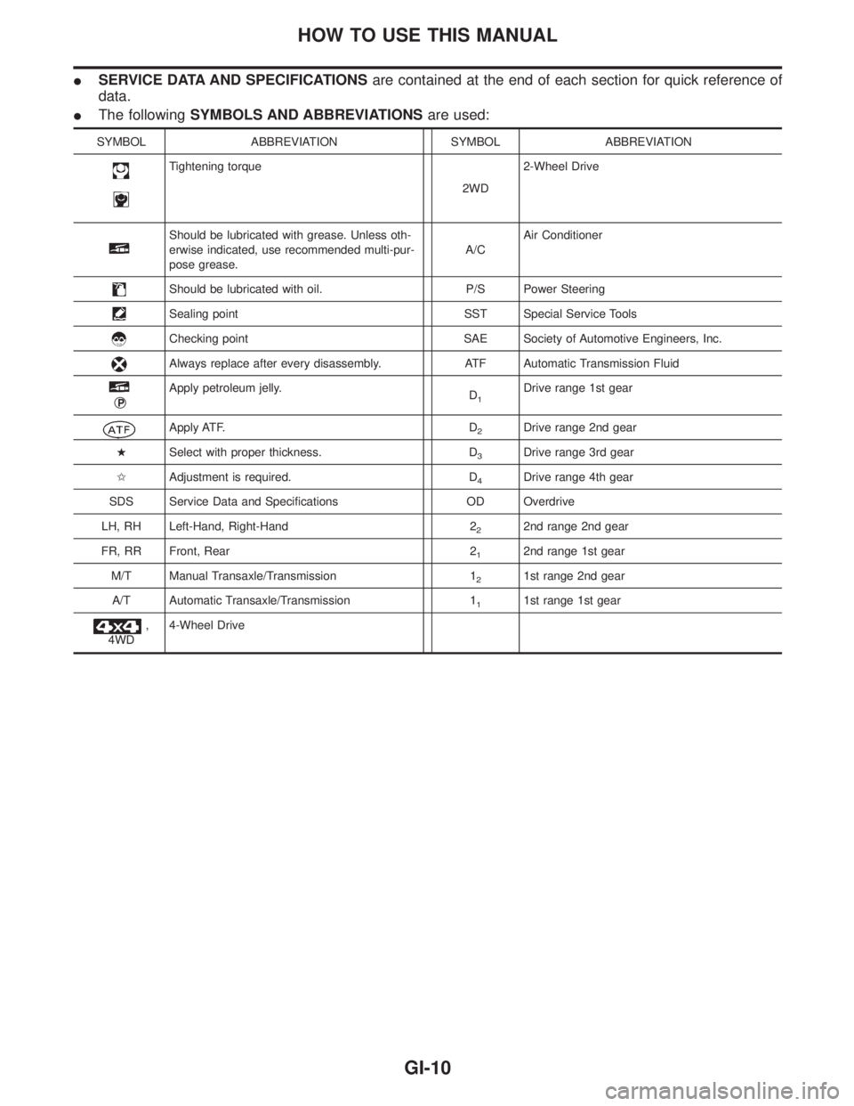
ISERVICE DATA AND SPECIFICATIONSare contained at the end of each section for quick reference of
data.
IThe followingSYMBOLS AND ABBREVIATIONSare used:
SYMBOL ABBREVIATION SYMBOL ABBREVIATION
Tightening torque
2WD2-Wheel Drive
Should be lubricated with grease. Unless oth-
erwise indicated, use recommended multi-pur-
pose grease.A/CAir Conditioner
Should be lubricated with oil. P/S Power Steering
Sealing point SST Special Service Tools
Checking point SAE Society of Automotive Engineers, Inc.
Always replace after every disassembly. ATF Automatic Transmission Fluid
qP
Apply petroleum jelly.
D1Drive range 1st gear
Apply ATF. D2Drive range 2nd gear
HSelect with proper thickness. D
3Drive range 3rd gear
IAdjustment is required. D
4Drive range 4th gear
SDS Service Data and Specifications OD Overdrive
LH, RH Left-Hand, Right-Hand 2
22nd range 2nd gear
FR, RR Front, Rear 2
12nd range 1st gear
M/T Manual Transaxle/Transmission 1
21st range 2nd gear
A/T Automatic Transaxle/Transmission 1
11st range 1st gear
,
4WD4-Wheel Drive
HOW TO USE THIS MANUAL
GI-10