check engine INFINITI QX4 2001 Factory Service Manual
[x] Cancel search | Manufacturer: INFINITI, Model Year: 2001, Model line: QX4, Model: INFINITI QX4 2001Pages: 2395, PDF Size: 43.2 MB
Page 1977 of 2395

IInspect the oil cooler after removing it.
SLC333B
3. Installation is in reverse order of removal.
IWhen installing the oil cooler, align the oil cooler stopper
with the stopper of the oil cooler bracket.
INSPECTIONNBLC0037Oil CoolerNBLC0037S011. Check oil cooler for cracks.
2. Check oil cooler for clogging by blowing through coolant inlet.
If necessary, replace oil cooler assembly.
Oil Pressure Relief ValveNBLC0037S02Inspect oil pressure relief valve for movement, cracks and breaks
by pushing the ball. If replacement is necessary, remove valve by
prying it out with a suitable tool. Install a new valve in place by
tapping it.
Service Data and Specifications (SDS)
OIL PRESSURENBLC0010
Engine speed
rpmApproximate discharge pressure
kPa (kg/cm2, psi)
Idle speed
2,000More than 98 (1.0, 14)
294 (3.0, 43)
REGULATOR VALVENBLC0011Unit: mm (in)
Regulator valve to oil pump cover clearance 0.040 - 0.097 (0.0016 - 0.0038)
OIL PUMPNBLC0012Unit: mm (in)
Body to outer rotor radial clearance 0.114 - 0.200 (0.0045 - 0.0079)
Inner rotor to outer rotor tip clearance Below 0.18 (0.0071)
Body to inner rotor axial clearance 0.030 - 0.070 (0.0012 - 0.0028)
Body to outer rotor axial clearance 0.050 - 0.110 (0.0020 - 0.0043)
Inner rotor to brazed portion of housing clearance 0.045 - 0.091 (0.0018 - 0.0036)
ENGINE LUBRICATION SYSTEM
Oil Cooler (Cont'd)
LC-8
Page 1980 of 2395

System CheckNBLC0016WARNING:
Never remove the radiator cap when the engine is hot; serious
burns could be caused by high pressure fluid escaping from
the radiator.
Wrap a thick cloth around the cap and carefully remove it by
turning it a quarter turn to allow built-up pressure to escape
and then turn the cap all the way off.
CHECKING COOLING SYSTEM HOSESNBLC0016S01Check hoses for improper attachment, leaks, cracks, damage,
loose connections, chafing and deterioration.
CHECKING RADIATORNBLC0016S02Check radiator for mud or clogging. If necessary, clean radiator as
follows.
IBe careful not to bend or damage the radiator fins.
IWhen radiator is cleaned without removal, remove all sur-
rounding parts such as cooling fan, radiator shroud and horns.
Then tape the harness and connectors to prevent water from
entering.
1. Apply water by hose to the back side of the radiator core ver-
tically downward.
2. Apply water again to all radiator core surfaces once per
minute.
3. Stop washing if any stains no longer flow out from the radia-
tor.
4. Blow air into the back side of radiator core vertically downward.
IUse compressed air lower than 490 kPa (5 kg/cm
2, 71 psi) and
keep distance more than 30 cm (11.8 in).
5. Blow air again into all the radiator core surfaces once per
minute until no water sprays out.
SLC755A
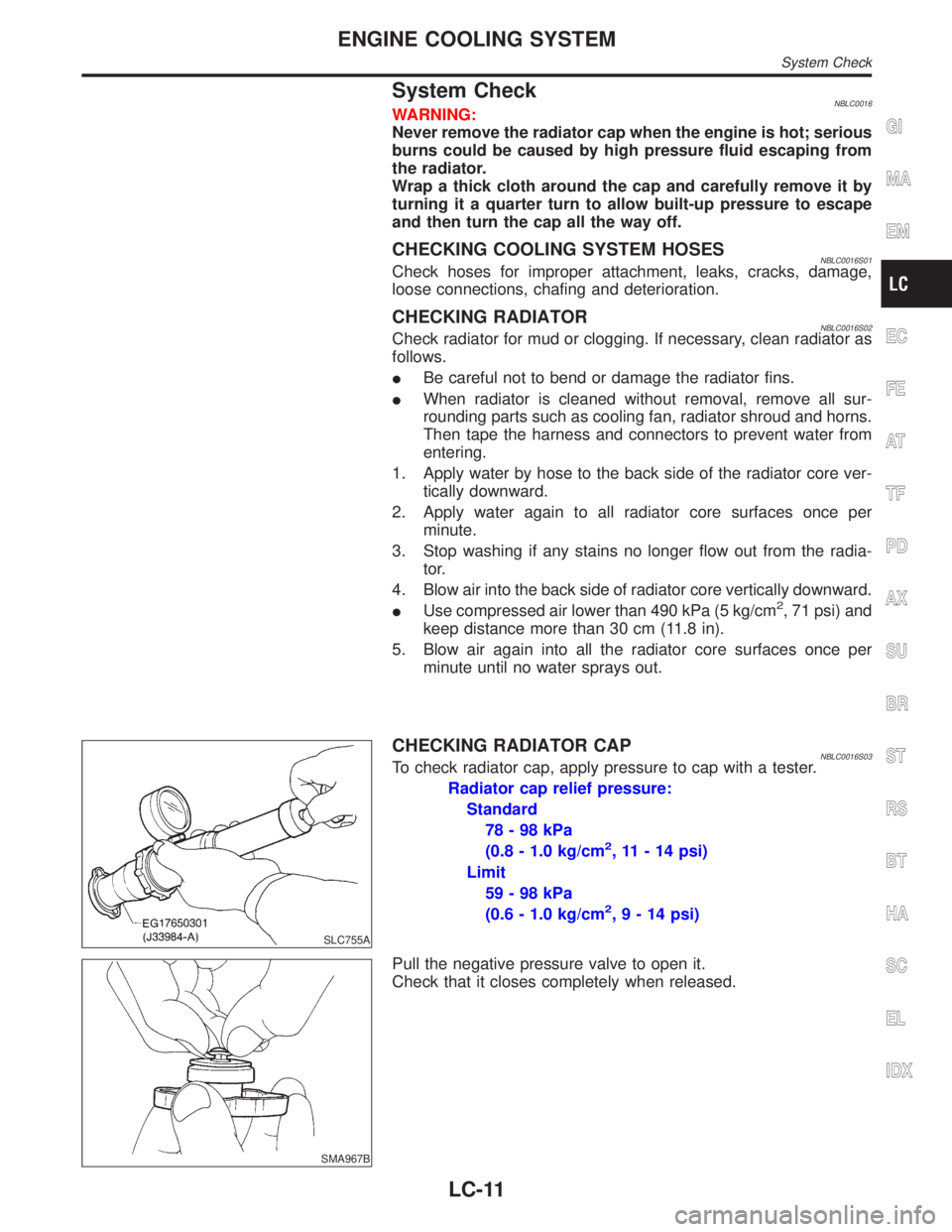
CHECKING RADIATOR CAPNBLC0016S03To check radiator cap, apply pressure to cap with a tester.
Radiator cap relief pressure:
Standard
78-98kPa
(0.8 - 1.0 kg/cm
2, 11 - 14 psi)
Limit
59-98kPa
(0.6 - 1.0 kg/cm
2,9-14psi)
SMA967B
Pull the negative pressure valve to open it.
Check that it closes completely when released.
GI
MA
EM
EC
FE
AT
TF
PD
AX
SU
BR
ST
RS
BT
HA
SC
EL
IDX
ENGINE COOLING SYSTEM
System Check
LC-11
Page 1981 of 2395

SLC756A
CHECKING COOLING SYSTEM FOR LEAKSNBLC0016S04To check for leakage, apply pressure to the cooling system with a
tester.
Testing pressure:
157 kPa (1.6 kg/cm
2, 23 psi)
CAUTION:
Higher than the specified pressure may cause radiator
damage.
Water Pump
REMOVAL AND INSTALLATIONNBLC0017CAUTION:
IWhen removing water pump assembly, be careful not to
get coolant on drive belt.
IWater pump cannot be disassembled and should be
replaced as a unit.
IAfter installing water pump, connect hose and clamp
securely, then check for leaks using radiator cap tester.
SLC326B
SLC327B
REMOVALNBLC00181. Remove under cover.
2. Remove suspension member stay.
3. Drain coolant from radiator.
4. Remove radiator shrouds.
5. Remove drive belts.
6. Remove cooling fan.
7. Remove water drain plug on water pump side of cylinder block.
8. Remove chain tensioner cover and water pump cover.
ENGINE COOLING SYSTEM
System Check (Cont'd)
LC-12
Page 1983 of 2395

SLC116B
12. Tighten M8 bolts by turning half turn alternately until they reach
timing chain rear case.
IIn order to prevent damages to water pump or timing chain rear
case, do not tighten one bolt continuously. Always turn each
bolt half turn each time.
13. Lift up water pump and remove it.
IWhen lifting up water pump, do not allow water pump gear to
hit timing chain.
SLC943A
INSPECTIONNBLC00191. Check for badly rusted or corroded body assembly.
2. Check for rough operation due to excessive end play.
SLC244B
INSTALLATIONNBLC00201. Apply engine oil and coolant to O-rings as shown in the figure.
ENGINE COOLING SYSTEM
Water Pump (Cont'd)
LC-14
Page 1985 of 2395

Thermostat
REMOVAL AND INSTALLATIONNBLC0021
SLC329B
SLC962AA
1. Remove under cover.
2. Remove suspension member stay.
3. Drain coolant from radiator.
4. Remove drive belts.
5. Remove water drain plug on water pump side of cylinder block.
6. Disconnect lower radiator hose.
7. Remove water inlet and thermostat assembly.
IDo not disassemble water inlet and thermostat. Replace
them as a unit, if necessary.
SLC948A
8. Install thermostat with jiggle valve facing upward.
IAfter installation, run engine for a few minutes, and check
for leaks.
IBe careful not to spill coolant over engine compartment.
Use a rag to absorb coolant.
9. Reinstall any removed parts in reverse order of removal.
SLC949A
INSPECTIONNBLC00221. Check valve seating condition at ordinary room temperatures.
It should seat tightly.
2. Check valve opening temperature and maximum valve lift.
Standard
Valve opening temperature 76.5ÉC (170ÉF)
Valve lift More than 8.6 mm/90ÉC
(0.339 in/194ÉF)
ENGINE COOLING SYSTEM
Thermostat
LC-16
Page 1986 of 2395

3. Then check if valve closes at 5ÉC (9ÉF) below valve opening
temperature.
Water Control Valve
REMOVAL AND INSTALLATIONNBLC0032
SLC330B
1. Water outlet housing
2. Water control valve
3. Water outlet4. Water hose
5. Cylinder block water outlet
6. Thermal transmitter7. Engine coolant temperature sen-
sor
1. Release fuel pressure.
Refer to EC-39, ªFuel Pressure Releaseº.
2. Remove under cover.
3. Remove suspension member stay.
4. Drain coolant from radiator.
5. Remove engine cover.
6. Remove air duct with air cleaner assembly.
7. Disconnect wires, hoses, harness and so on.
8. Remove upper intake manifold corrector.
9. Remove intake manifold corrector support bolts.
10. Remove lower intake manifold corrector.
11. Disconnect injector harness connectors.
12. Remove injector tube.
13. Remove intake manifold.
14. Remove water outlet housing and water control valve.
GI
MA
EM
EC
FE
AT
TF
PD
AX
SU
BR
ST
RS
BT
HA
SC
EL
IDX
ENGINE COOLING SYSTEM
Thermostat (Cont'd)
LC-17
Page 1987 of 2395

SLC334B
15. Install water control valve and water outlet housing.
a. Install gum ring to thermostat.
b. Point the arrow on the upper surface of the valve to the front
of the engine, and also be sure to install the protrusions and
the valve stopper so that they are aligned in a straight line.
16. Reinstall any removed parts in reverse order of removal.
IWhen installing intake manifold, injector tube and intake
manifold collectors, refer to EM-12, ªTIGHTENING PROCE-
DURESº.
IAfter installation, run engine for a few minutes, and check
for leaks.
IBe careful not to spill coolant over engine compartment.
Use a rag to absorb coolant.
SLC252B
INSPECTIONNBLC00331. Check valve seating condition at ordinary room temperatures.
It should seat tightly.
2. Check valve opening temperature and maximum valve lift.
Standard
Valve opening temperature 95ÉC (203ÉF)
Valve lift More than 8.0 mm/108ÉC
(0.315 in/226ÉF)
3. Then check if valve closes at 5ÉC (9ÉF) below valve opening
temperature.
ENGINE COOLING SYSTEM
Water Control Valve (Cont'd)
LC-18
Page 1989 of 2395

SLC066B
Cooling Fan (Crankshaft driven)
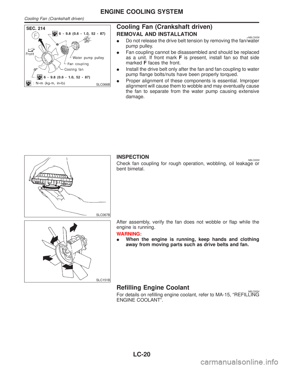
REMOVAL AND INSTALLATION=NBLC0038IDo not release the drive belt tension by removing the fan/water
pump pulley.
IFan coupling cannot be disassembled and should be replaced
as a unit. If front markFis present, install fan so that side
markedFfaces the front.
IInstall the drive belt only after the fan and fan coupling to water
pump flange bolts/nuts have been properly torqued.
IProper alignment of these components is essential. Improper
alignment will cause them to wobble and may eventually cause
the fan to separate from the water pump causing extensive
damage.
SLC067B
INSPECTIONNBLC0039Check fan coupling for rough operation, wobbling, oil leakage or
bent bimetal.
SLC151B
After assembly, verify the fan does not wobble or flap while the
engine is running.
WARNING:
IWhen the engine is running, keep hands and clothing
away from moving parts such as drive belts and fan.
Refilling Engine CoolantNBLC0034For details on refilling engine coolant, refer to MA-15, ªREFILLING
ENGINE COOLANTº.
ENGINE COOLING SYSTEM
Cooling Fan (Crankshaft driven)
LC-20
Page 1993 of 2395

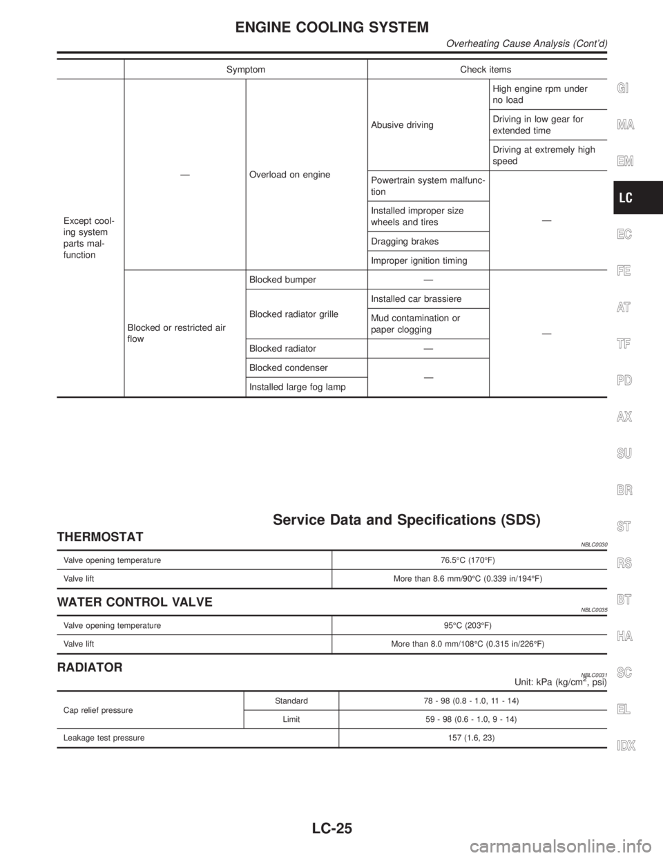
Overheating Cause AnalysisNBLC0029
Symptom Check items
Cooling sys-
tem parts
malfunctionPoor heat transferWater pump malfunction Worn or loose drive belt
Ð Thermostat stuck closed Ð
Damaged finsDust contamination or
paper clogging
Mechanical damage
Clogged radiator cooling
tubeExcess foreign material
(rust, dirt, sand, etc.)
Reduced air flowCooling fan does not oper-
ate
ÐÐ High resistance to fan rota-
tion
Damaged fan blades
Damaged radiator shroud Ð Ð Ð
Improper coolant mixture
ratioÐÐÐ
Poor coolant quality Ð Ð Ð
Insufficient coolantCoolant leaksCooling hoseLoose clamp
Cracked hose
Water pump Poor sealing
Radiator capLoose
Poor sealing
RadiatorO-ring for damage, dete-
rioration or improper fit-
ting
Cracked radiator tank
Cracked radiator core
Reservoir tank Cracked reservoir tank
Overflowing reservoir tankExhaust gas leaks into
cooling systemCylinder head deteriora-
tion
Cylinder head gasket
deterioration
ENGINE COOLING SYSTEM
Overheating Cause Analysis
LC-24
Page 1994 of 2395

Symptom Check items
Except cool-
ing system
parts mal-
functionÐ Overload on engineAbusive drivingHigh engine rpm under
no load
Driving in low gear for
extended time
Driving at extremely high
speed
Powertrain system malfunc-
tion
Ð Installed improper size
wheels and tires
Dragging brakes
Improper ignition timing
Blocked or restricted air
flowBlocked bumper Ð
Ð Blocked radiator grilleInstalled car brassiere
Mud contamination or
paper clogging
Blocked radiator Ð
Blocked condenser
Ð
Installed large fog lamp
Service Data and Specifications (SDS)
THERMOSTATNBLC0030
Valve opening temperature76.5ÉC (170ÉF)
Valve liftMore than 8.6 mm/90ÉC (0.339 in/194ÉF)
WATER CONTROL VALVENBLC0035
Valve opening temperature95ÉC (203ÉF)
Valve liftMore than 8.0 mm/108ÉC (0.315 in/226ÉF)
RADIATORNBLC0031Unit: kPa (kg/cm2, psi)
Cap relief pressureStandard 78 - 98 (0.8 - 1.0, 11 - 14)
Limit 59 - 98 (0.6 - 1.0,9-14)
Leakage test pressure157 (1.6, 23)
GI
MA
EM
EC
FE
AT
TF
PD
AX
SU
BR
ST
RS
BT
HA
SC
EL
IDX
ENGINE COOLING SYSTEM
Overheating Cause Analysis (Cont'd)
LC-25