check engine INFINITI QX4 2001 Factory Service Manual
[x] Cancel search | Manufacturer: INFINITI, Model Year: 2001, Model line: QX4, Model: INFINITI QX4 2001Pages: 2395, PDF Size: 43.2 MB
Page 1769 of 2395

NBGI0004
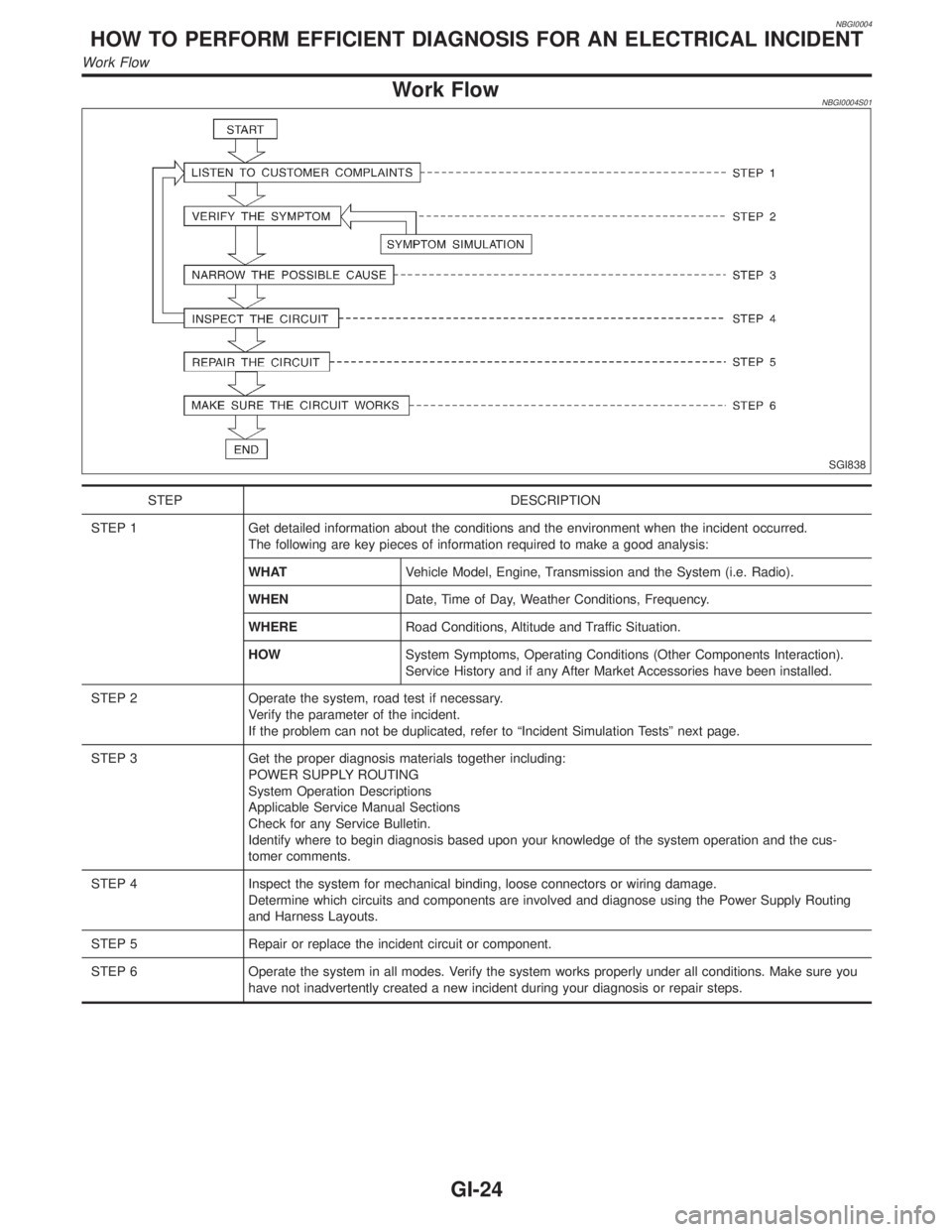
Work FlowNBGI0004S01
SGI838
STEP DESCRIPTION
STEP 1 Get detailed information about the conditions and the environment when the incident occurred.
The following are key pieces of information required to make a good analysis:
WHATVehicle Model, Engine, Transmission and the System (i.e. Radio).
WHENDate, Time of Day, Weather Conditions, Frequency.
WHERERoad Conditions, Altitude and Traffic Situation.
HOWSystem Symptoms, Operating Conditions (Other Components Interaction).
Service History and if any After Market Accessories have been installed.
STEP 2 Operate the system, road test if necessary.
Verify the parameter of the incident.
If the problem can not be duplicated, refer to ªIncident Simulation Testsº next page.
STEP 3 Get the proper diagnosis materials together including:
POWER SUPPLY ROUTING
System Operation Descriptions
Applicable Service Manual Sections
Check for any Service Bulletin.
Identify where to begin diagnosis based upon your knowledge of the system operation and the cus-
tomer comments.
STEP 4 Inspect the system for mechanical binding, loose connectors or wiring damage.
Determine which circuits and components are involved and diagnose using the Power Supply Routing
and Harness Layouts.
STEP 5 Repair or replace the incident circuit or component.
STEP 6 Operate the system in all modes. Verify the system works properly under all conditions. Make sure you
have not inadvertently created a new incident during your diagnosis or repair steps.
HOW TO PERFORM EFFICIENT DIAGNOSIS FOR AN ELECTRICAL INCIDENT
Work Flow
GI-24
Page 1770 of 2395

Incident Simulation TestsNBGI0004S02INTRODUCTIONNBGI0004S0201Sometimes the symptom is not present when the vehicle is brought
in for service. If possible, re-create the conditions present at the
time of the incident. Doing so may help avoid a No Trouble Found
Diagnosis. The following section illustrates ways to simulate the
conditions/environment under which the owner experiences an
electrical incident.
The section is broken into the six following topics:
IVehicle vibration
IHeat sensitive
IFreezing
IWater intrusion
IElectrical load
ICold or hot start up
Get a thorough description of the incident from the customer. It is
important for simulating the conditions of the problem.
VEHICLE VIBRATIONNBGI0004S0202The problem may occur or become worse while driving on a rough
road or when engine is vibrating (idle with A/C on). In such a case,
you will want to check for a vibration related condition. Refer to the
illustration below.
Connectors & Harness
Determine which connectors and wiring harness would affect the
electrical system you are inspecting.Gentlyshake each connec-
tor and harness while monitoring the system for the incident you
are trying to duplicate. This test may indicate a loose or poor elec-
trical connection.
Hint
Connectors can be exposed to moisture. It is possible to get a thin
film of corrosion on the connector terminals. A visual inspection
may not reveal this without disconnecting the connector. If the
problem occurs intermittently, perhaps the problem is caused by
corrosion. It is a good idea to disconnect, inspect and clean the
terminals on related connectors in the system.
Sensors & Relays
Gentlyapply a slight vibration to sensors and relays in the system
you are inspecting.
This test may indicate a loose or poorly mounted sensor or relay.
SGI839
MA
EM
LC
EC
FE
AT
TF
PD
AX
SU
BR
ST
RS
BT
HA
SC
EL
IDX
HOW TO PERFORM EFFICIENT DIAGNOSIS FOR AN ELECTRICAL INCIDENT
Incident Simulation Tests
GI-25
Page 1771 of 2395

Engine Compartment
There are several reasons a vehicle or engine vibration could
cause an electrical complaint. Some of the things to check for are:
IConnectors not fully seated.
IWiring harness not long enough and is being stressed due to
engine vibrations or rocking.
IWires laying across brackets or moving components.
ILoose, dirty or corroded ground wires.
IWires routed too close to hot components.
To inspect components under the hood, start by verifying the integ-
rity of ground connections. (Refer to GROUND INSPECTION
described later.) First check that the system is properly grounded.
Then check for loose connection bygently shakingthe wiring or
components as previously explained. Using the wiring diagrams
inspect the wiring for continuity.
Behind The Instrument Panel
An improperly routed or improperly clamped harness can become
pinched during accessory installation. Vehicle vibration can aggra-
vate a harness which is routed along a bracket or near a screw.
Under Seating Areas
An unclamped or loose harness can cause wiring to be pinched by
seat components (such as slide guides) during vehicle vibration. If
the wiring runs under seating areas, inspect wire routing for pos-
sible damage or pinching.
SGI842
HEAT SENSITIVENBGI0004S0203The owner's problem may occur during hot weather or after car has
sat for a short time. In such cases you will want to check for a heat
sensitive condition.
To determine if an electrical component is heat sensitive, heat the
component with a heat gun or equivalent.
Do not heat components above 60ÉC (140ÉF).If incident occurs
while heating the unit, either replace or properly insulate the com-
ponent.
SGI843
FREEZINGNBGI0004S0204The customer may indicate the incident goes away after the car
warms up (winter time). The cause could be related to water freez-
ing somewhere in the wiring/electrical system.
There are two methods to check for this. The first is to arrange for
the owner to leave his car overnight. Make sure it will get cold
enough to demonstrate his complaint. Leave the car parked out-
side overnight. In the morning, do a quick and thorough diagnosis
of those electrical components which could be affected.
HOW TO PERFORM EFFICIENT DIAGNOSIS FOR AN ELECTRICAL INCIDENT
Incident Simulation Tests (Cont'd)
GI-26
Page 1781 of 2395

Key to Symbols Signifying Measurements or
Procedures
NBGI0005S02
Symbol Symbol explanation Symbol Symbol explanation
Check after disconnecting the con-
nector to be measured.Procedure with Generic Scan Tool
(GST, OBD-II scan tool)
Check after connecting the connec-
tor to be measured.Procedure without CONSULT-II or
GST
Insert key into ignition switch.A/C switch is ªOFFº.
Remove key from ignition switch.A/C switch is ªONº.
Turn ignition switch to ªOFFº posi-
tion.REC switch is ªONº.
Turn ignition switch to ªONº position.REC switch is ªOFFº.
Turn ignition switch to ªSTARTº posi-
tion.Fan switch is ªONº. (At any position
except for ªOFFº position)
Turn ignition switch from ªOFFº to
ªACCº position.Fan switch is ªOFFº.
Turn ignition switch from ªACCº to
ªOFFº position.Apply positive voltage from battery
with fuse directly to components.
Turn ignition switch from ªOFFº to
ªONº position.Drive vehicle.
Turn ignition switch from ªONº to
ªOFFº position.Disconnect battery negative cable.
Do not start engine, or check with
engine stopped.Depress brake pedal.
Start engine, or check with engine
running.Release brake pedal.
Apply parking brake.Depress accelerator pedal.
Release parking brake.Release accelerator pedal.
HOW TO FOLLOW TROUBLE DIAGNOSIS
Key to Symbols Signifying Measurements or Procedures
GI-36
Page 1782 of 2395

Symbol Symbol explanation Symbol Symbol explanation
Check after engine is warmed up
sufficiently.Pin terminal check for SMJ type
ECM and TCM connectors.
For details regarding the terminal
arrangement, refer to the ªELEC-
TRICAL UNITSº electrical refer-
ence page at the end of the
manual.
Voltage should be measured with a
voltmeter.
Circuit resistance should be mea-
sured with an ohmmeter.
Current should be measured with an
ammeter.
Procedure with CONSULT-II
Procedure without CONSULT-II
MA
EM
LC
EC
FE
AT
TF
PD
AX
SU
BR
ST
RS
BT
HA
SC
EL
IDX
HOW TO FOLLOW TROUBLE DIAGNOSIS
Key to Symbols Signifying Measurements or Procedures (Cont'd)
GI-37
Page 1783 of 2395

NBGI0006
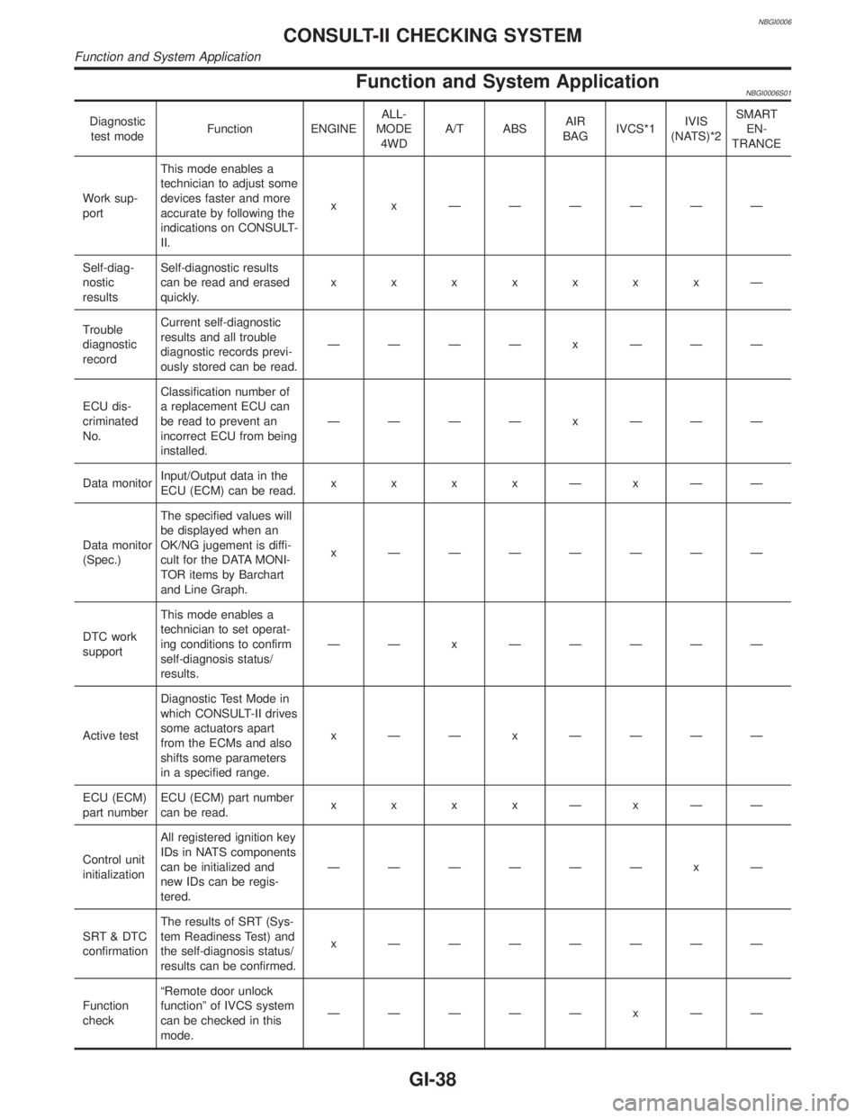
Function and System ApplicationNBGI0006S01
Diagnostic
test modeFunction ENGINEALL-
MODE
4WDA/T ABSAIR
BAGIVCS*1IVIS
(NATS)*2SMART
EN-
TRANCE
Work sup-
portThis mode enables a
technician to adjust some
devices faster and more
accurate by following the
indications on CONSULT-
II.x x ÐÐÐÐÐÐ
Self-diag-
nostic
resultsSelf-diagnostic results
can be read and erased
quickly.xxxxxxxÐ
Trouble
diagnostic
recordCurrent self-diagnostic
results and all trouble
diagnostic records previ-
ously stored can be read.ÐÐÐÐ x ÐÐÐ
ECU dis-
criminated
No.Classification number of
a replacement ECU can
be read to prevent an
incorrect ECU from being
installed.ÐÐÐÐ x ÐÐÐ
Data monitorInput/Output data in the
ECU (ECM) can be read.x x x xÐxÐÐ
Data monitor
(Spec.)The specified values will
be displayed when an
OK/NG jugement is diffi-
cult for the DATA MONI-
TOR items by Barchart
and Line Graph.x ÐÐÐÐÐÐÐ
DTC work
supportThis mode enables a
technician to set operat-
ing conditions to confirm
self-diagnosis status/
results.ÐÐ x ÐÐÐÐÐ
Active testDiagnostic Test Mode in
which CONSULT-II drives
some actuators apart
from the ECMs and also
shifts some parameters
in a specified range.x ÐÐ x ÐÐÐÐ
ECU (ECM)
part numberECU (ECM) part number
can be read.x x x xÐxÐÐ
Control unit
initializationAll registered ignition key
IDs in NATS components
can be initialized and
new IDs can be regis-
tered.ÐÐÐÐÐÐ x Ð
SRT & DTC
confirmationThe results of SRT (Sys-
tem Readiness Test) and
the self-diagnosis status/
results can be confirmed.x ÐÐÐÐÐÐÐ
Function
checkªRemote door unlock
functionº of IVCS system
can be checked in this
mode.ÐÐÐÐÐ x ÐÐ
CONSULT-II CHECKING SYSTEM
Function and System Application
GI-38
Page 1784 of 2395

Diagnostic
test modeFunction ENGINEALL-
MODE
4WDA/T ABSAIR
BAGIVCS*1IVIS
(NATS)*2SMART
EN-
TRANCE
Registered
dataDisplay the VIN, etc. data
registered in the IVCS
unit.ÐÐÐÐÐ x ÐÐ
Configura-
tionIThe IVCS system can
be set up in the dem-
onstration mode to
confirm system opera-
tion.
IVarious data related to
both the Communica-
tor Response Center
contract and cellular
provider can be
written/rewritten in this
mode.ÐÐÐÐÐ x ÐÐ
REMO
CONT ID
SET UPA maximum of four IDs
(identifications) can be
registered in the memory
using the remote control-
ler. These IDs can be
also be confirmed and
erased as required.ÐÐÐÐÐÐÐ x
x: Applicable
*1: INFINITI Communicator (IVCS)
*2: IVIS (NATS) [INFINITI Vehicle Immobilizer System (Nissan Anti-Theft System)]
Nickel Metal Hydride Battery ReplacementNBGI0006S06CONSULT-II contains a nickel metal hydride battery. When replacing the battery obey the following:
WARNING:
Replace the nickel metal hydride battery with Genuine CONSULT-II battery only. Use of another bat-
tery may present a risk of fire or explosion. The battery may present a fire or chemical burn hazard if
mistreated. Do not recharge, disassemble of dispose of in fire.
Keep the battery out of reach of children and discard used battery conforming to the local regulations.
Checking EquipmentNBGI0006S07When ordering the below equipment, contact your NISSAN/INFINITI distributor.
Tool name Description
NISSAN CONSULT-II
q
1CONSULT-II unit (Tester internal soft:
Resident version 3.2.0) and accessories
q
2Program card AED99C (Version 3.0)
and UEN99A (For IVIS and IVCS)
To confirm the best combination of these
softwares, refer to CONSULT-II Operation
Manual.
SGI100A
NOTE:
IThe CONSULT-II must be used in conjunction with a program card.
CONSULT-II does not require loading (Initialization) procedure.
IBe sure the CONSULT-II is turned off before installing or removing a program card.
MA
EM
LC
EC
FE
AT
TF
PD
AX
SU
BR
ST
RS
BT
HA
SC
EL
IDX
CONSULT-II CHECKING SYSTEM
Function and System Application (Cont'd)
GI-39
Page 1797 of 2395

NEW TERMNEW ACRONYM /
ABBREVIATIONOLD TERM
Evaporative emission canister EVAP canister Canister
Evaporative emission system EVAP system Canister control solenoid valve
Exhaust gas recirculation valve EGR valve EGR valve
Exhaust gas recirculation control-BPT
valveEGRC-BPT valve BPT valve
Exhaust gas recirculation control-solenoid
valveEGRC-solenoid valve EGR control solenoid valve
Exhaust gas recirculation temperature
sensorEGRT sensor Exhaust gas temperature sensor
EGR temperature sensor
Flash electrically erasable programmable
read only memoryFEEPROM ***
Flash erasable programmable read only
memoryFEPROM ***
Flexible fuel sensor FFS ***
Flexible fuel system FF system ***
Fuel pressure regulator *** Pressure regulator
Fuel pressure regulator control solenoid
valve*** PRVR control solenoid valve
Fuel tank temperature sensor FTT sensor Tank fuel temperature sensor
Fuel trim FT ***
Heated Oxygen sensor HO2S Exhaust gas sensor
Idle air control system IAC system Idle speed control
Idle air control valve-air regulator IACV-air regulator Air regulator
Idle air control valve-auxiliary air control
valveIACV-AAC valve Auxiliary air control (AAC) valve
Idle air control valve-FICD solenoid valve IACV-FICD solenoid valve FICD solenoid valve
Idle air control valve-idle up control sole-
noid valveIACV-idle up control solenoid valve Idle up control solenoid valve
Idle speed control-FI pot ISC-FI pot FI pot
Idle speed control system ISC system ***
Ignition control IC ***
Ignition control module ICM ***
Indirect fuel injection system IFI system ***
Intake air IA Air
Intake air temperature sensor IAT sensor Air temperature sensor
Knock *** Detonation
Knock sensor KS Detonation sensor
Malfunction indicator lamp MIL Check engine light
Manifold absolute pressure MAP ***
Manifold absolute pressure sensor MAPS ***
SAE J1930 TERMINOLOGY LIST
SAE J1930 Terminology List (Cont'd)
GI-52
Page 1800 of 2395

HEATER &
AIR CONDITIONER
SECTION
HA
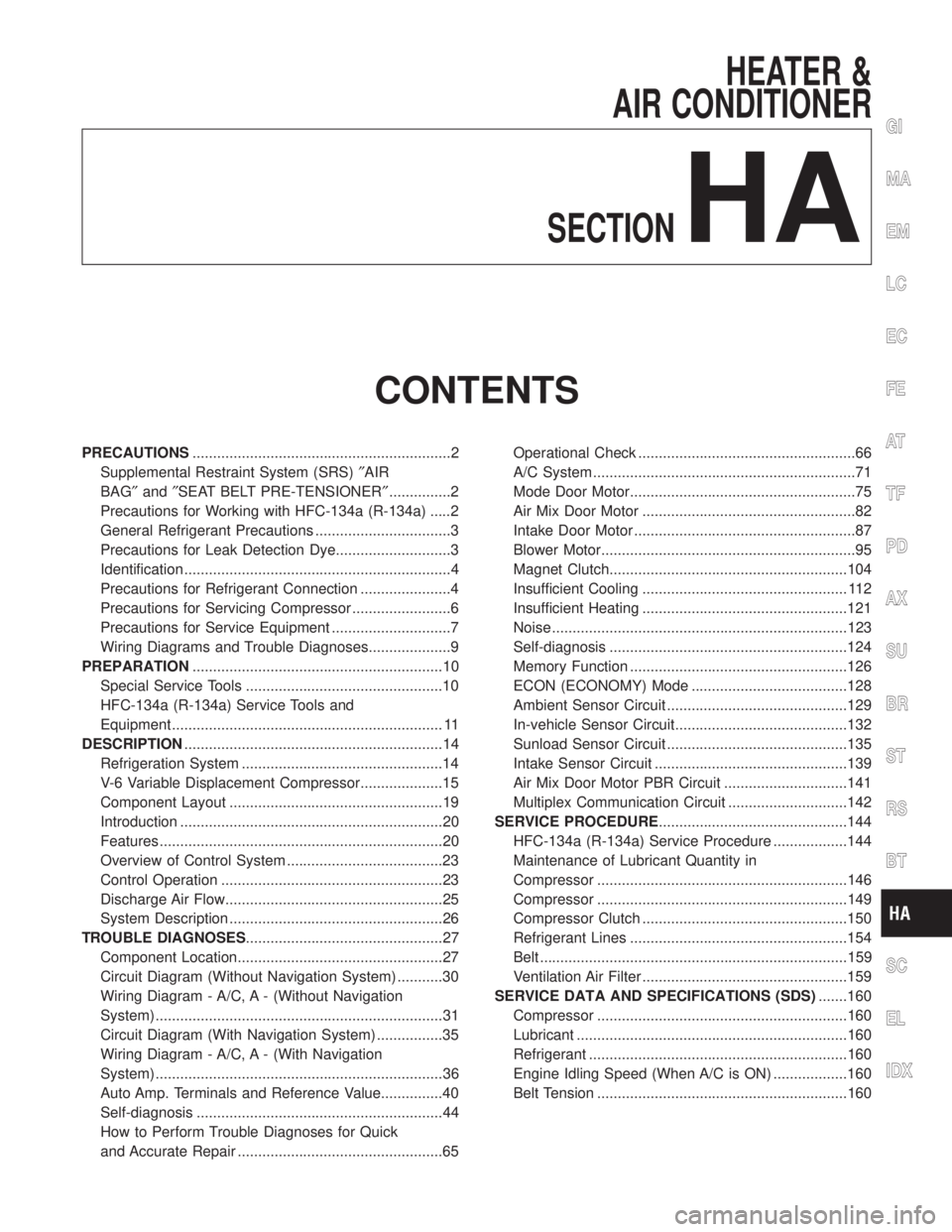
CONTENTS
PRECAUTIONS...............................................................2
Supplemental Restraint System (SRS)²AIR
BAG²and²SEAT BELT PRE-TENSIONER²...............2
Precautions for Working with HFC-134a (R-134a) .....2
General Refrigerant Precautions .................................3
Precautions for Leak Detection Dye............................3
Identification .................................................................4
Precautions for Refrigerant Connection ......................4
Precautions for Servicing Compressor ........................6
Precautions for Service Equipment .............................7
Wiring Diagrams and Trouble Diagnoses....................9
PREPARATION.............................................................10
Special Service Tools ................................................10
HFC-134a (R-134a) Service Tools and
Equipment .................................................................. 11
DESCRIPTION...............................................................14
Refrigeration System .................................................14
V-6 Variable Displacement Compressor....................15
Component Layout ....................................................19
Introduction ................................................................20
Features .....................................................................20
Overview of Control System ......................................23
Control Operation ......................................................23
Discharge Air Flow.....................................................25
System Description ....................................................26
TROUBLE DIAGNOSES................................................27
Component Location..................................................27
Circuit Diagram (Without Navigation System) ...........30
Wiring Diagram - A/C, A - (Without Navigation
System) ......................................................................31
Circuit Diagram (With Navigation System) ................35
Wiring Diagram - A/C, A - (With Navigation
System) ......................................................................36
Auto Amp. Terminals and Reference Value...............40
Self-diagnosis ............................................................44
How to Perform Trouble Diagnoses for Quick
and Accurate Repair ..................................................65Operational Check .....................................................66
A/C System ................................................................71
Mode Door Motor.......................................................75
Air Mix Door Motor ....................................................82
Intake Door Motor ......................................................87
Blower Motor..............................................................95
Magnet Clutch..........................................................104
Insufficient Cooling .................................................. 112
Insufficient Heating ..................................................121
Noise ........................................................................123
Self-diagnosis ..........................................................124
Memory Function .....................................................126
ECON (ECONOMY) Mode ......................................128
Ambient Sensor Circuit ............................................129
In-vehicle Sensor Circuit..........................................132
Sunload Sensor Circuit ............................................135
Intake Sensor Circuit ...............................................139
Air Mix Door Motor PBR Circuit ..............................141
Multiplex Communication Circuit .............................142
SERVICE PROCEDURE..............................................144
HFC-134a (R-134a) Service Procedure ..................144
Maintenance of Lubricant Quantity in
Compressor .............................................................146
Compressor .............................................................149
Compressor Clutch ..................................................150
Refrigerant Lines .....................................................154
Belt ...........................................................................159
Ventilation Air Filter ..................................................159
SERVICE DATA AND SPECIFICATIONS (SDS).......160
Compressor .............................................................160
Lubricant ..................................................................160
Refrigerant ...............................................................160
Engine Idling Speed (When A/C is ON) ..................160
Belt Tension .............................................................160
GI
MA
EM
LC
EC
FE
AT
TF
PD
AX
SU
BR
ST
RS
BT
SC
EL
IDX
Page 1805 of 2395

CAUTION:
When replacing or cleaning refrigerant cycle components, observe the following.
IWhen the compressor is removed, store it in the same position as it is when mounted on the car.
Failure to do so will cause lubricant to enter the low pressure chamber.
IWhen connecting tubes, always use a torque wrench and a back-up wrench.
IAfter disconnecting tubes, immediately plug all openings to prevent entry of dirt and moisture.
IWhen installing an air conditioner in the vehicle, connect the pipes as the final stage of the opera-
tion. Do not remove the seal caps of pipes and other components until just before required for
connection.
IAllow components stored in cool areas to warm to working area temperature before removing seal
caps. This prevents condensation from forming inside A/C components.
IThoroughly remove moisture from the refrigeration system before charging the refrigerant.
IAlways replace used O-rings.
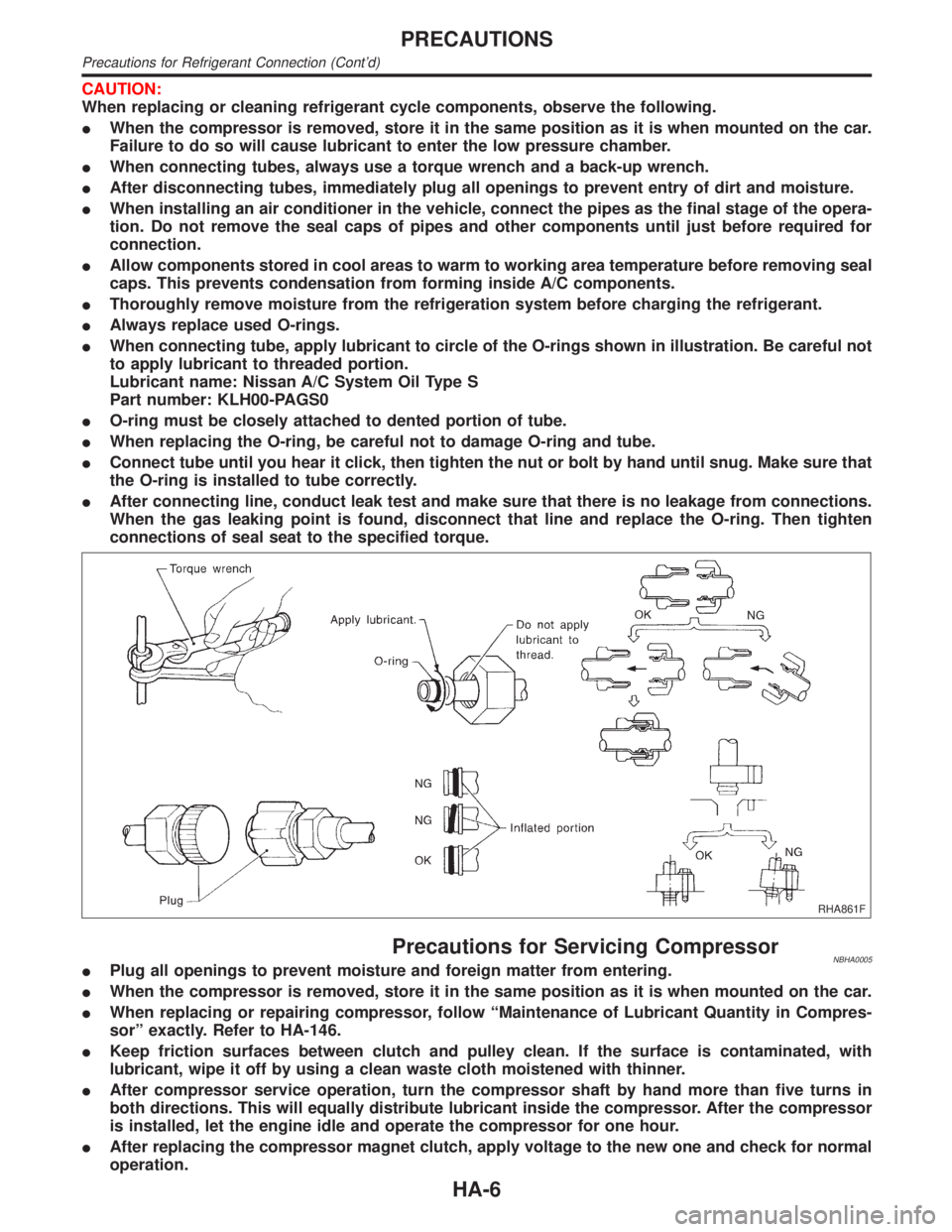
IWhen connecting tube, apply lubricant to circle of the O-rings shown in illustration. Be careful not
to apply lubricant to threaded portion.
Lubricant name: Nissan A/C System Oil Type S
Part number: KLH00-PAGS0
IO-ring must be closely attached to dented portion of tube.
IWhen replacing the O-ring, be careful not to damage O-ring and tube.
IConnect tube until you hear it click, then tighten the nut or bolt by hand until snug. Make sure that
the O-ring is installed to tube correctly.
IAfter connecting line, conduct leak test and make sure that there is no leakage from connections.
When the gas leaking point is found, disconnect that line and replace the O-ring. Then tighten
connections of seal seat to the specified torque.
RHA861F
Precautions for Servicing CompressorNBHA0005IPlug all openings to prevent moisture and foreign matter from entering.
IWhen the compressor is removed, store it in the same position as it is when mounted on the car.
IWhen replacing or repairing compressor, follow ªMaintenance of Lubricant Quantity in Compres-
sorº exactly. Refer to HA-146.
IKeep friction surfaces between clutch and pulley clean. If the surface is contaminated, with
lubricant, wipe it off by using a clean waste cloth moistened with thinner.
IAfter compressor service operation, turn the compressor shaft by hand more than five turns in
both directions. This will equally distribute lubricant inside the compressor. After the compressor
is installed, let the engine idle and operate the compressor for one hour.
IAfter replacing the compressor magnet clutch, apply voltage to the new one and check for normal
operation.
PRECAUTIONS
Precautions for Refrigerant Connection (Cont'd)
HA-6