check engine INFINITI QX4 2001 Factory Service Manual
[x] Cancel search | Manufacturer: INFINITI, Model Year: 2001, Model line: QX4, Model: INFINITI QX4 2001Pages: 2395, PDF Size: 43.2 MB
Page 2191 of 2395
6. If rack sliding force is not within specification, overhaul steer-
ing gear assembly.
7. If rack sliding force is OK, inspect steering column. Refer to
ªInspectionº, ªSTEERING WHEEL AND STEERING
COLUMNº, ST-14.
SST834-F
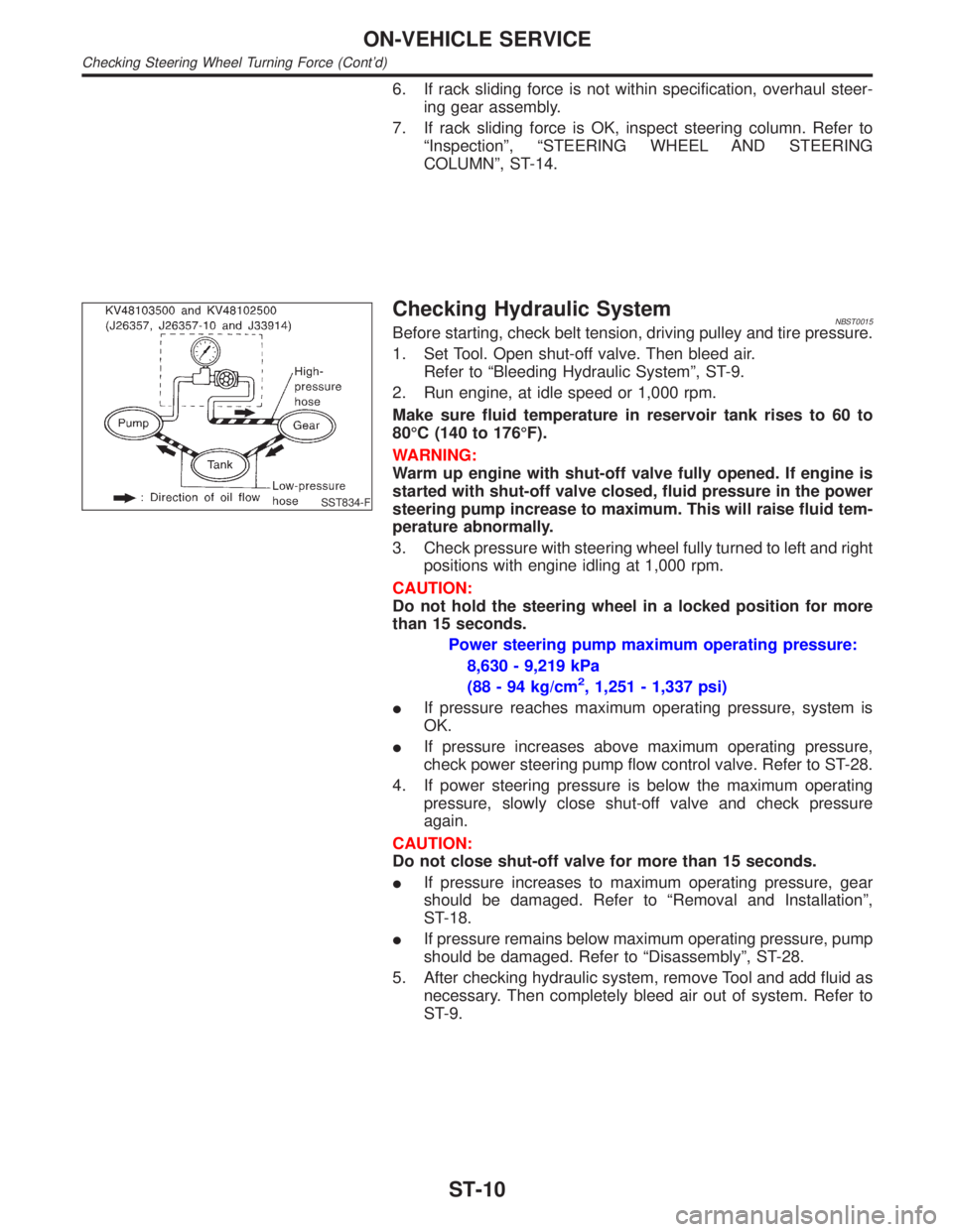
Checking Hydraulic SystemNBST0015Before starting, check belt tension, driving pulley and tire pressure.
1. Set Tool. Open shut-off valve. Then bleed air.
Refer to ªBleeding Hydraulic Systemº, ST-9.
2. Run engine, at idle speed or 1,000 rpm.
Make sure fluid temperature in reservoir tank rises to 60 to
80ÉC (140 to 176ÉF).
WARNING:
Warm up engine with shut-off valve fully opened. If engine is
started with shut-off valve closed, fluid pressure in the power
steering pump increase to maximum. This will raise fluid tem-
perature abnormally.
3. Check pressure with steering wheel fully turned to left and right
positions with engine idling at 1,000 rpm.
CAUTION:
Do not hold the steering wheel in a locked position for more
than 15 seconds.
Power steering pump maximum operating pressure:
8,630 - 9,219 kPa
(88 - 94 kg/cm
2, 1,251 - 1,337 psi)
IIf pressure reaches maximum operating pressure, system is
OK.
IIf pressure increases above maximum operating pressure,
check power steering pump flow control valve. Refer to ST-28.
4. If power steering pressure is below the maximum operating
pressure, slowly close shut-off valve and check pressure
again.
CAUTION:
Do not close shut-off valve for more than 15 seconds.
IIf pressure increases to maximum operating pressure, gear
should be damaged. Refer to ªRemoval and Installationº,
ST-18.
IIf pressure remains below maximum operating pressure, pump
should be damaged. Refer to ªDisassemblyº, ST-28.
5. After checking hydraulic system, remove Tool and add fluid as
necessary. Then completely bleed air out of system. Refer to
ST-9.
ON-VEHICLE SERVICE
Checking Steering Wheel Turning Force (Cont'd)
ST-10
Page 2206 of 2395
SST718CA
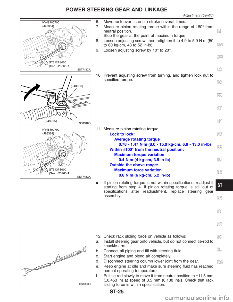
6. Move rack over its entire stroke several times.
7. Measure pinion rotating torque within the range of 180É from
neutral position.
Stop the gear at the point of maximum torque.
8. Loosen adjusting screw, then retighten it to 4.9 to 5.9 N´m (50
to 60 kg-cm, 43 to 52 in-lb).
9. Loosen adjusting screw by 10É to 20É.
SST940C
10. Prevent adjusting screw from turning, and tighten lock nut to
specified torque.
SST718CA
11. Measure pinion rotating torque.
Lock to lock:
Average rotating torque
0.78 - 1.47 N´m (8.0 - 15.0 kg-cm, 6.9 - 13.0 in-lb)
Within±100É from the neutral position:
Maximum torque variation
0.4 N´m (4 kg-cm, 3.5 in-lb)
Outside the above range:
Maximum force variation
0.6 N´m (6 kg-cm, 5.2 in-lb)
IIf pinion rotating torque is not within specifications, readjust it
starting from step 4. If pinion rotating torque is still out of
specifications after readjustment, replace steering gear
assembly.
SST090B
12. Check rack sliding force on vehicle as follows:
a. Install steering gear onto vehicle, but do not connect tie-rod to
knuckle arm.
b. Connect all piping and fill with steering fluid.
c. Start engine and bleed air completely.
d. Disconnect steering column lower joint from the gear.
e. Keep engine at idle and make sure steering fluid has reached
normal operating temperature.
f. Pull tie-rod slowly to move it from neutral position to±11.5 mm
(±0.453 in) at speed of 3.5 mm (0.138 in)/s. Check that rack
sliding force is within specification.
GI
MA
EM
LC
EC
FE
AT
TF
PD
AX
SU
BR
RS
BT
HA
SC
EL
IDX
POWER STEERING GEAR AND LINKAGE
Adjustment (Cont'd)
ST-25
Page 2217 of 2395
SBR686C
Precautions
PRECAUTIONSNBSU0001IWhen installing rubber parts, final tightening must be car-
ried out under unladen condition* with tires on ground.
*Fuel, radiator coolant and engine oil full. Spare tire, jack,
hand tools and mats in designated positions.
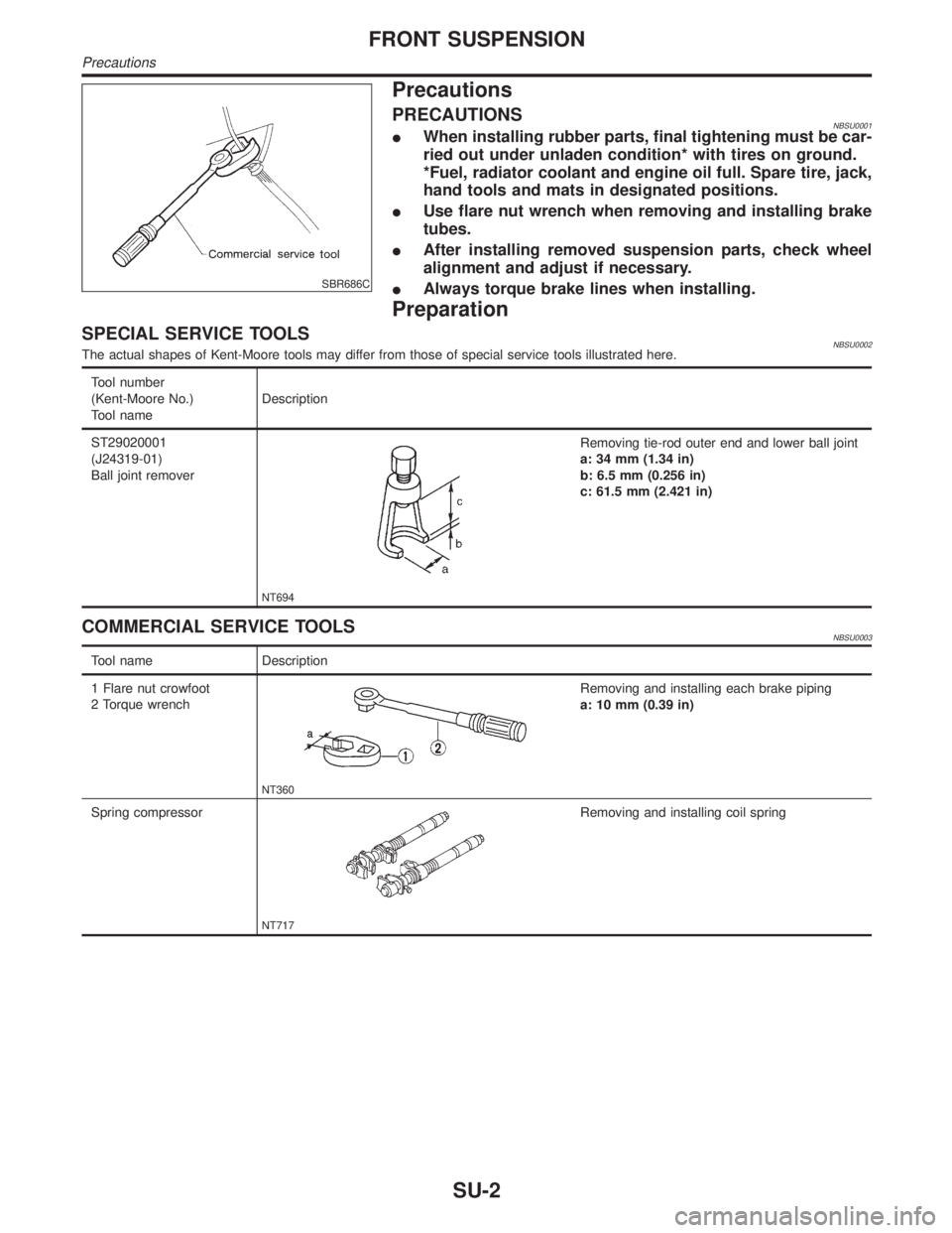
IUse flare nut wrench when removing and installing brake
tubes.
IAfter installing removed suspension parts, check wheel
alignment and adjust if necessary.
IAlways torque brake lines when installing.
Preparation
SPECIAL SERVICE TOOLSNBSU0002The actual shapes of Kent-Moore tools may differ from those of special service tools illustrated here.
Tool number
(Kent-Moore No.)
Tool nameDescription
ST29020001
(J24319-01)
Ball joint remover
NT694
Removing tie-rod outer end and lower ball joint
a: 34 mm (1.34 in)
b: 6.5 mm (0.256 in)
c: 61.5 mm (2.421 in)
COMMERCIAL SERVICE TOOLSNBSU0003
Tool name Description
1 Flare nut crowfoot
2 Torque wrench
NT360
Removing and installing each brake piping
a: 10 mm (0.39 in)
Spring compressor
NT717
Removing and installing coil spring
FRONT SUSPENSION
Precautions
SU-2
Page 2220 of 2395
SMA525A
On-vehicle Service
FRONT SUSPENSION PARTSNBSU0005Check front axle and front suspension parts for excessive play,
cracks, wear and other damage.
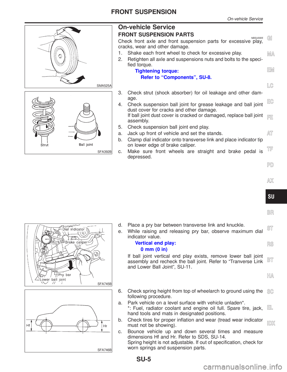
1. Shake each front wheel to check for excessive play.
2. Retighten all axle and suspensions nuts and bolts to the speci-
fied torque.
Tightening torque:
Refer to ªComponentsº, SU-8.
SFA392B
3. Check strut (shock absorber) for oil leakage and other dam-
age.
4. Check suspension ball joint for grease leakage and ball joint
dust cover for cracks and other damage.
If ball joint dust cover is cracked or damaged, replace ball joint
assembly.
5. Check suspension ball joint end play.
a. Jack up front of vehicle and set the stands.
b. Clamp dial indicator onto transverse link and place indicator tip
on lower edge of brake caliper.
c. Make sure front wheels are straight and brake pedal is
depressed.
SFA745B
d. Place a pry bar between transverse link and knuckle.
e. While raising and releasing pry bar, observe maximum dial
indicator value.
Vertical end play:
0mm(0in)
If ball joint vertical end play exists, remove lower ball joint
assembly and recheck the ball joint. Refer to ªTranverse Link
and Lower Ball Jointº, SU-11.
SFA746B
6. Check spring height from top of wheelarch to ground using the
following procedure.
a. Park vehicle on a level surface with vehicle unladen*.
*: Fuel, radiator coolant and engine oil full. Spare tire, jack,
hand tools and mats in designated positions.
b. Check tires for proper inflation and wear (tread wear indicator
must not be showing).
c. Bounce vehicle up and down several times and measure
dimensions Hf and Hr. Refer to SDS, SU-14.
Spring height is not adjustable. If out of specification, check for
worn springs and suspension parts.
GI
MA
EM
LC
EC
FE
AT
TF
PD
AX
BR
ST
RS
BT
HA
SC
EL
IDX
FRONT SUSPENSION
On-vehicle Service
SU-5
Page 2221 of 2395
SFA975B
FRONT WHEEL ALIGNMENTNBSU0006Before checking front wheel alignment, be sure to make a prelimi-
nary inspection (Unladen*).
*: Fuel, radiator coolant and engine oil full. Spare tire, jack, hand
tools and mats in designated positions.
Preliminary InspectionNBSU0006S011. Check tires for wear and improper inflation.
2. Check wheels for deformation, cracks and other damage.
If deformed, remove wheel and check wheel runout.
NOTE:
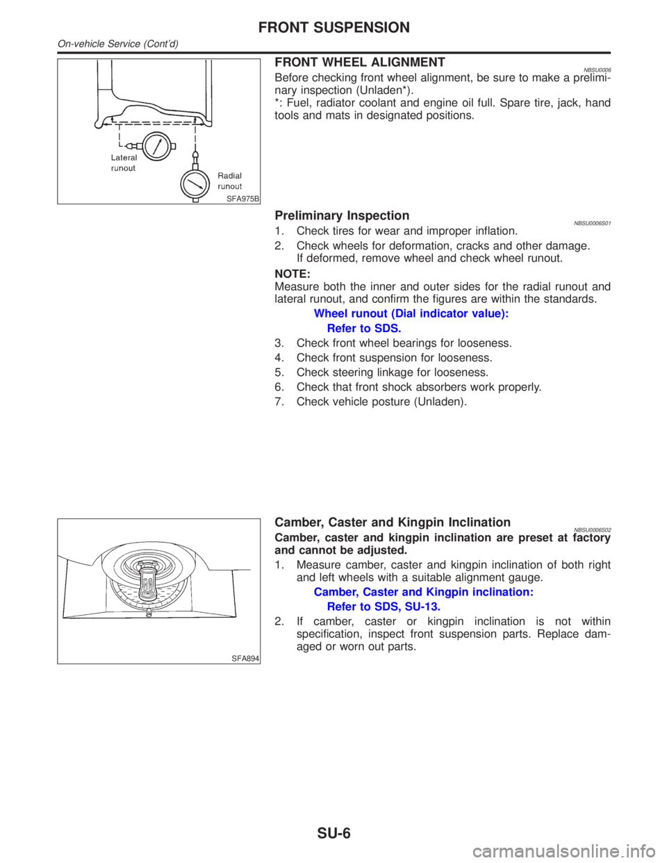
Measure both the inner and outer sides for the radial runout and
lateral runout, and confirm the figures are within the standards.
Wheel runout (Dial indicator value):
Refer to SDS.
3. Check front wheel bearings for looseness.
4. Check front suspension for looseness.
5. Check steering linkage for looseness.
6. Check that front shock absorbers work properly.
7. Check vehicle posture (Unladen).
SFA894
Camber, Caster and Kingpin InclinationNBSU0006S02Camber, caster and kingpin inclination are preset at factory
and cannot be adjusted.
1. Measure camber, caster and kingpin inclination of both right
and left wheels with a suitable alignment gauge.
Camber, Caster and Kingpin inclination:
Refer to SDS, SU-13.
2. If camber, caster or kingpin inclination is not within
specification, inspect front suspension parts. Replace dam-
aged or worn out parts.
FRONT SUSPENSION
On-vehicle Service (Cont'd)
SU-6
Page 2230 of 2395

SBR686C
Precautions
PRECAUTIONSNBSU0021IWhen installing rubber parts, final tightening must be car-
ried out under unladen condition* with tires on ground.
*Fuel, radiator coolant and engine oil full. Spare tire, jack,
hand tools and mats in designated positions.
IUse flare nut wrench when removing and installing brake
tubes.
IAfter installing removed suspension parts, check wheel
alignment and adjust if necessary.
IAlways torque brake lines when installing.
Preparation
COMMERCIAL SERVICE TOOLSNBSU0023
Tool name Description
1 Flare nut crowfoot
2 Torque wrench
NT360
Removing and installing each brake piping
a: 10 mm (0.39 in)
Noise, Vibration and Harshness (NVH)
Troubleshooting
NBSU0036Refer to ªNoise, Vibration and Harshness (NVH) Troubleshootingº,
ªFRONT SUSPENSIONº, SU-3.
GI
MA
EM
LC
EC
FE
AT
TF
PD
AX
BR
ST
RS
BT
HA
SC
EL
IDX
REAR SUSPENSION
Precautions
SU-15
Page 2236 of 2395
TRANSFER
SECTION
TF
CONTENTS
PRECAUTIONS...............................................................3
Supplemental Restraint System (SRS)²AIR
BAG²and²SEAT BELT PRE-TENSIONER²...............3
Precautions ..................................................................3
Service Notice..............................................................4
Wiring Diagrams and Trouble Diagnosis .....................4
PREPARATION...............................................................5
Special Service Tools ..................................................5
Commercial Service Tools ...........................................9
ALL-MODE 4WD SYSTEM...........................................10
Cross-sectional View .................................................10
Control System .......................................................... 11
ALL-MODE 4WD TRANSFER BASIC CONTROL........12
HYDRAULIC CONTROL CIRCUITS...........................12
OUTLINE................................................................12
CONTROL SYSTEM DIAGRAM................................13
INDICATIONS OF 4WD WARNING LAMP..................13
Location of Electrical Parts ........................................14
Description of Electrical Parts ...................................15
TRANSFER MOTOR................................................15
WAIT DETECTION SWITCH.....................................15
2-4WD SHIFT SOLENOID VALVE.............................16
LINE PRESSURE SWITCH.......................................16
Circuit Diagram for Quick Pinpoint Check.................17
Wiring Diagram - TF -................................................18
ON BOARD DIAGNOSTIC SYSTEM
DESCRIPTION...............................................................27
Trouble Diagnosis without CONSULT-II ....................27
DESCRIPTION........................................................27
SELF-DIAGNOSTIC PROCEDURE............................28
INDICATIONS OF 4WD WARNING LAMP..................29
Trouble Diagnosis with CONSULT-II .........................30
SELF-DIAGNOSIS...................................................30
SELF-DIAGNOSTIC ITEMS......................................31
DATA MONITOR......................................................33
DATA MONITOR ITEMS...........................................34
REFERENCE VALUE IN DATA MONITOR MODE......36
WORK SUPPORT....................................................38
CLUTCH FORCE RELEASE LIMIT ADJUSTMENT.....39
TROUBLE DIAGNOSIS - INTRODUCTION..................41Introduction ................................................................41
DESCRIPTION........................................................41
DIAGNOSTIC WORKSHEET.....................................41
Work Flow ..................................................................43
HOW TO PERFORM TROUBLE DIAGNOSES FOR
QUICK AND ACCURATE REPAIR
.............................43
TROUBLE DIAGNOSIS - BASIC INSPECTION...........44
Listen to Customer Complaints .................................44
Transfer Fluid Check .................................................44
Road Test...................................................................44
PREPARATION FOR ROAD TEST............................44
1. CHECK BEFORE ENGINE IS STARTED...............45
2. CHECK AT IDLE..................................................47
3. CRUISE TEST.....................................................51
TROUBLE DIAGNOSIS - GENERAL
DESCRIPTION...............................................................54
Transfer Control Unit Terminals and Reference
Value ..........................................................................54
REMOVAL AND INSTALLATION OF TRANSFER
CONTROL UNIT
......................................................54
INSPECTION OF TRANSFER CONTROL UNIT..........54
TRANSFER CONTROL UNIT INSPECTION TABLE....55
VEHICLE SPEED SENSOR (FRONT
REVOLUTION SENSOR)..............................................61
Diagnostic Procedure ................................................61
4WD SOLENOID VALVE...............................................64
Diagnostic Procedure ................................................64
2-4WD SHIFT SOLENOID VALVE AND 4WD
SHIFT SWITCH..............................................................66
Diagnostic Procedure ................................................66
TRANSFER MOTOR AND TRANSFER MOTOR
RELAY...........................................................................70
Diagnostic Procedure ................................................70
TRANSFER FLUID TEMPERATURE SENSOR............73
Diagnostic Procedure ................................................73
ATP SWITCH, WAIT DETECTION SWITCH AND
NEUTRAL-4LO SWITCH...............................................76
Diagnostic Procedure ................................................76
CLUTCH PRESSURE SWITCH....................................80
Diagnostic Procedure ................................................80
GI
MA
EM
LC
EC
FE
AT
PD
AX
SU
BR
ST
RS
BT
HA
SC
EL
IDX
Page 2248 of 2395

CONTROL SYSTEM DIAGRAMNBTF0007S04
SMT763D
INDICATIONS OF 4WD WARNING LAMPNBTF0007S05
Condition Content 4WD warning lamp
During self-diagnosis Indicates the malfunction position by number of flickers. Flickers at malfunction mode.
Lamp check*Checks the lamp by turning ON during engine starting. After
engine starts, it turns OFF if there are no malfunctions.ON
Malfunction in 4WD system*Turns ON to indicate malfunction. When ignition switch is
turned to ªOFFº or the malfunction is corrected, it turns OFF.ON
When vehicle is driven with different
diameters of front and rear tiresFlickers once every 2 seconds.
Turns OFF when ignition switch is ªOFFº.Flickers once every 2 sec-
onds.
High fluid temperature in transfer
unitWhen fluid temperature is high or fluid temperature sensor
circuit is shorted, it flickers twice every second.
It turns OFF when fluid temperature becomes normal.Flickers twice a second.
Other than above (System is nor-
mal.)Lamp is OFF. OFF
*: When 4WD warning lamp is ON, all the 4WD shift indicator lamps turn OFF.
GI
MA
EM
LC
EC
FE
AT
PD
AX
SU
BR
ST
RS
BT
HA
SC
EL
IDX
ALL-MODE 4WD SYSTEM
Control System (Cont'd)
TF-13
Page 2264 of 2395

INDICATIONS OF 4WD WARNING LAMPNBTF0011S03
Flickering pattern or flick-
ering conditionMalfunction Check items
1 Front revolution sensor circuit is shorted or open.Revolution sensor (front) circuit,
TF-61.
2 Rear revolution sensor circuit is shorted or open.Revolution sensor (rear) [Refer to
AT-111, ªDTC P0720 Vehicle Speed
Sensor´A/T (Revolution sensor)º.]
3 4WD solenoid valve circuit is shorted or open. 4WD solenoid valve circuit, TF-64.
42-4WD shift solenoid valve circuit is shorted or 2WD switch of
4WD shift switch is shorted.2-4WD shift solenoid valve circuit or
4WD shift switch circuit, TF-66.
5 Transfer motor relay circuit is shorted or open. Transfer motor relay circuit, TF-70.
8Power supply voltage of throttle position sensor is improper. Or
A/D converter of transfer control unit functions improperly.Throttle position sensor (Refer to
AT-176, ªDTC P1705 Throttle Posi-
tion Sensorº.)
9 Transfer fluid temperature sensor circuit is open.Transfer fluid temperature sensor
circuit, TF-73.
10 Neutral-4LO switch circuit is shorted or open. Neutral-4LO switch circuit, TF-76.
112-4WD shift solenoid valve circuit, 2WD switch of 4WD shift
switch circuit or clutch pressure switch circuit is shorted or open.2-4WD shift solenoid valve circuit,
4WD shift switch circuit or clutch
pressure switch circuit, TF-66, 80.
12 Line pressure switch circuit is shorted or open. Line pressure switch circuit, TF-83.
13 Engine speed signal circuit is shorted or open.Engine speed signal (Refer to
AT-116, ªDTC P0725 Engine Speed
Signalº.)
14 Throttle position sensor circuit is shorted or open.Throttle position sensor (Refer to
AT-176, ªDTC P1705 Throttle Posi-
tion Sensorº.)
15 Failure in power supply circuit of transfer control unit. Power supply of transfer control unit
16 4WD shift switch circuit is shorted. 4WD shift switch circuit, TF-66.
17 ABS operation signal circuit is shorted. ABS operation signal circuit, TF-86.
18ATP switch, wait detection switch or neutral-4LO switch circuit is
shorted or open.ATP switch, wait detection switch or
neutral-4LO switch circuit*, TF-76.
19Transfer control device actuator motor is faulty. (Abnormalities
are detected when actuator motor fails to operate while shifting
from ª4Hº to ª4LOº or vice versa.)Actuator motor and motor circuit,
TF-115, 89.
20Transfer control device actuator motor arm position sensing
switch is faulty.Actuator motor arm position sensing
switch and sensing switch circuit,
TF-115, 92.
21Transfer control device actuator circuit is faulty (Abnormalities
are detected when motor relay circuit is open/shorted or relay
monitor circuit is open/shorted.)Actuator motor, actuator motor arm
position sensing switch and their
associated circuits, TF-114, 115 and
94.
Repeats flickering every
2 to 5 sec.Circuits that the self-diagnosis covers have no malfunction. Ð
Repeats flickering every
0.25 sec.IPower supply failure of memory back-up.
IBattery is disconnected for a long time.
IBattery performance is poor.Data erase/display circuit, TF-88.GI
MA
EM
LC
EC
FE
AT
PD
AX
SU
BR
ST
RS
BT
HA
SC
EL
IDX
ON BOARD DIAGNOSTIC SYSTEM DESCRIPTION
Trouble Diagnosis without CONSULT-II (Cont'd)
TF-29
Page 2265 of 2395

Flickering pattern or flick-
ering conditionMalfunction Check items
No flickering PNP switch or 4WD shift switch circuit is shorted or open.PNP switch (Refer to AT-99, ªDTC
P0705 Park/Neutral Position
Switchº.) or 4WD shift switch circuit,
TF-66.
*: If revolution sensor malfunction is simultaneously detected, check revolution sensor first.
SAT601J
Trouble Diagnosis with CONSULT-IINBTF0012SELF-DIAGNOSISNBTF0012S01CONSULT-II Setting ProcedureNBTF0012S01011. Turn ignition switch to ªOFFº position.
SMT962D
2. Connect CONSULT-II to data link connector which is located
in instrument lower panel on driver side.
SAT586J
3. Start engine.
4. On CONSULT-II screen, touch ªSTARTº.
SMT964D
5. Touch ªALL MODE 4WDº on SELECT SYSTEM screen.
ON BOARD DIAGNOSTIC SYSTEM DESCRIPTION
Trouble Diagnosis without CONSULT-II (Cont'd)
TF-30