INFINITI QX4 2001 Factory Service Manual
Manufacturer: INFINITI, Model Year: 2001, Model line: QX4, Model: INFINITI QX4 2001Pages: 2395, PDF Size: 43.2 MB
Page 381 of 2395

SFA443B
6. Lock new larger boot band securely with a suitable tool, then
lock new smaller boot band.
7. Install new plug seal to slide joint housing by lightly tapping it.
Apply sealant to mating surface of plug seal.
SFA800
Wheel Side (ZF100)NBAX0020S021. Install new small boot band and boot on drive shaft.
Cover drive shaft serration with tape so as not to damage boot
during installation.
SFA884
2. Set joint assembly onto drive shaft by lightly tapping it.
Install joint assembly securely, ensuring marks which were
made during disassembly are properly aligned.
SFA473BA
3. Pack drive shaft with specified amount of grease.
Specified amount of grease:
135 - 145 g (4.76 - 5.11 oz)
4. Make sure that boot is properly installed on the drive shaft
groove. Set boot so that it does not swell and deform when its
length is ªL
2º.
Length ªL
2º: 96 - 98 mm (3.78 - 3.86 in)
5. Lock new larger boot band securely with a suitable tool.
6. Lock new smaller boot band.
SFA887
INSTALLATIONNBAX00211. Apply multi-purpose grease.
FRONT AXLE
Drive Shaft (Cont'd)
AX-14
Page 382 of 2395
SFA846-A
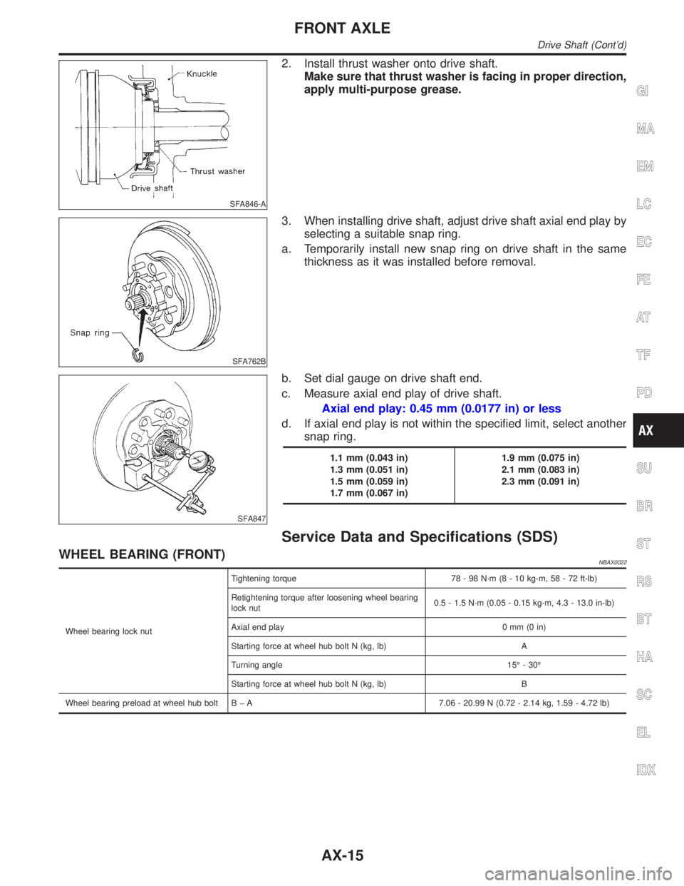
2. Install thrust washer onto drive shaft.
Make sure that thrust washer is facing in proper direction,
apply multi-purpose grease.
SFA762B
3. When installing drive shaft, adjust drive shaft axial end play by
selecting a suitable snap ring.
a. Temporarily install new snap ring on drive shaft in the same
thickness as it was installed before removal.
SFA847
b. Set dial gauge on drive shaft end.
c. Measure axial end play of drive shaft.
Axial end play: 0.45 mm (0.0177 in) or less
d. If axial end play is not within the specified limit, select another
snap ring.
1.1 mm (0.043 in)
1.3 mm (0.051 in)
1.5 mm (0.059 in)
1.7 mm (0.067 in)1.9 mm (0.075 in)
2.1 mm (0.083 in)
2.3 mm (0.091 in)
Service Data and Specifications (SDS)
WHEEL BEARING (FRONT)NBAX0022
Wheel bearing lock nutTightening torque 78 - 98 N´m (8 - 10 kg-m, 58 - 72 ft-lb)
Retightening torque after loosening wheel bearing
lock nut0.5 - 1.5 N´m (0.05 - 0.15 kg-m, 4.3 - 13.0 in-lb)
Axial end play 0 mm (0 in)
Starting force at wheel hub bolt N (kg, lb) A
Turning angle 15É - 30É
Starting force at wheel hub bolt N (kg, lb) B
Wheel bearing preload at wheel hub bolt B þ A 7.06 - 20.99 N (0.72 - 2.14 kg, 1.59 - 4.72 lb)
GI
MA
EM
LC
EC
FE
AT
TF
PD
SU
BR
ST
RS
BT
HA
SC
EL
IDX
FRONT AXLE
Drive Shaft (Cont'd)
AX-15
Page 383 of 2395

DRIVE SHAFT=NBAX0033
Drive shaft joint typeFinal drive sideTS82F
Wheel sideZF100
Fixed joint axial end play limit 1 mm (0.04 in)
Diameter Wheel side (D
1)29.0 mm (1.142 in)
GreaseQualityNissan genuine grease or equivalent
Specified amount of greaseFinal drive side 95 - 105 g (3.35 - 3.70 oz)
Wheel side 135 - 145 g (4.76 - 5.11 oz)
Drive shaft axial end play0.45 mm (0.0177 in) or less
Boot lengthFinal drive side (L
1) 95 - 97 mm (3.74 - 3.82 in)
Wheel side (L
2) 96 - 98 mm (3.78 - 3.86 in)
SAX001
Drive Shaft End Snap RingNBAX0033S01
Thickness mm (in) Part No. Thickness mm (in) Part No.
1.1 (0.043)
1.3 (0.051)
1.5 (0.059)
1.7 (0.067)39253-88G10
39253-88G11
39253-88G12
39253-88G131.9 (0.075)
2.1 (0.083)
2.3 (0.091)39253-88G14
39253-88G15
39253-88G16
FRONT AXLE
Service Data and Specifications (SDS) (Cont'd)
AX-16
Page 384 of 2395
SBR686C
Precautions
PRECAUTIONSNBAX0023IWhen installing rubber parts, final tightening must be car-
ried out under unladen condition* with tires on ground.
*Fuel, radiator coolant and engine oil full. Spare tire, jack,
hand tools and mats in designated positions.
IUse flare nut wrench when removing and installing brake
tubes.
IAfter installing removed suspension parts, check wheel
alignment and adjust if necessary.
IAlways torque brake lines when installing.
Preparation
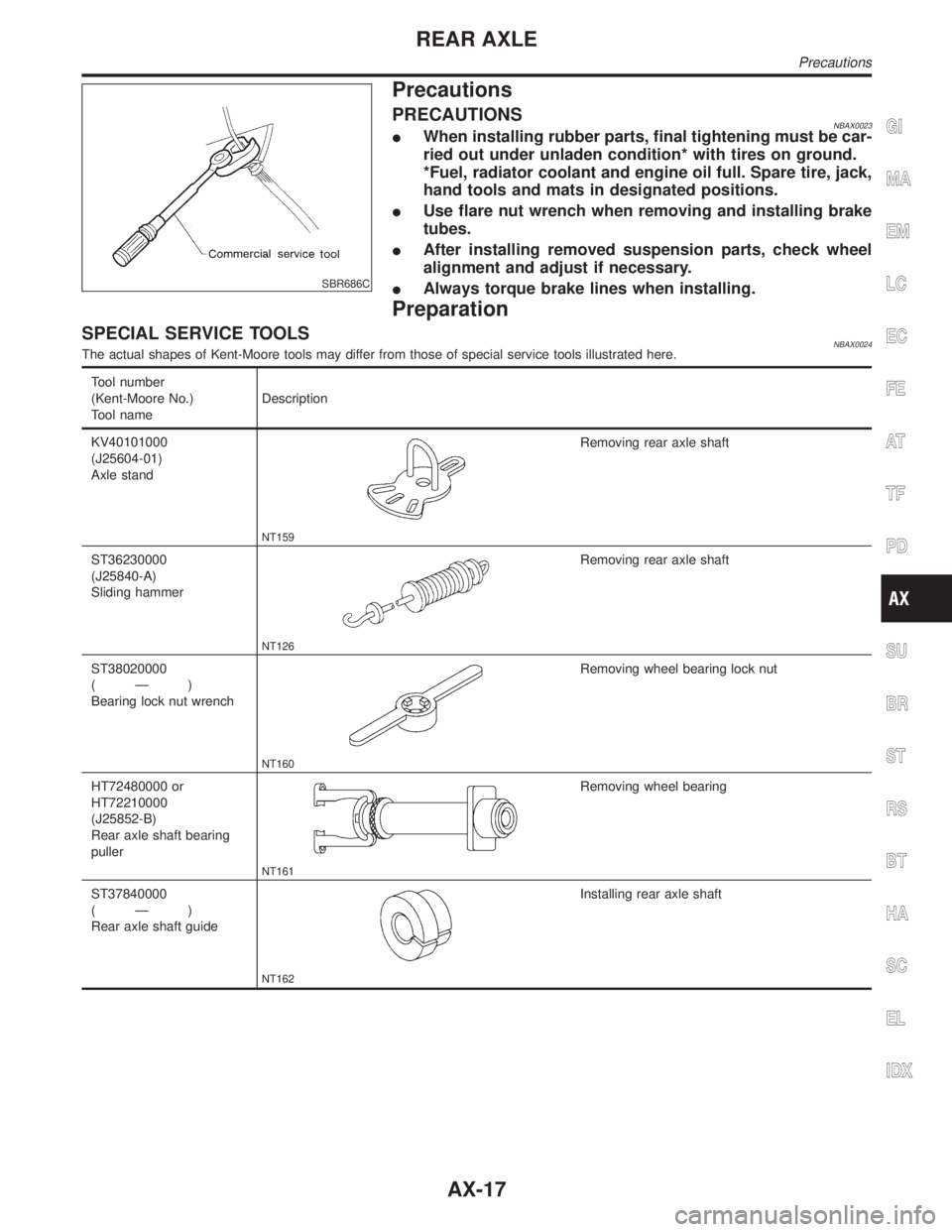
SPECIAL SERVICE TOOLSNBAX0024The actual shapes of Kent-Moore tools may differ from those of special service tools illustrated here.
Tool number
(Kent-Moore No.)
Tool nameDescription
KV40101000
(J25604-01)
Axle stand
NT159
Removing rear axle shaft
ST36230000
(J25840-A)
Sliding hammer
NT126
Removing rear axle shaft
ST38020000
(Ð)
Bearing lock nut wrench
NT160
Removing wheel bearing lock nut
HT72480000 or
HT72210000
(J25852-B)
Rear axle shaft bearing
puller
NT161
Removing wheel bearing
ST37840000
(Ð)
Rear axle shaft guide
NT162
Installing rear axle shaft
GI
MA
EM
LC
EC
FE
AT
TF
PD
SU
BR
ST
RS
BT
HA
SC
EL
IDX
REAR AXLE
Precautions
AX-17
Page 385 of 2395
COMMERCIAL SERVICE TOOLSNBAX0025
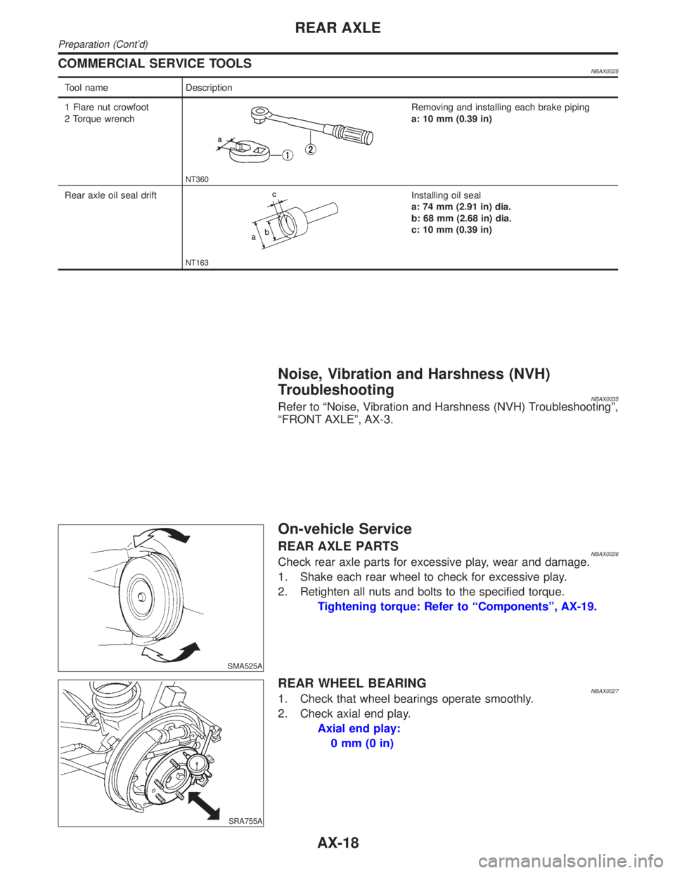
Tool name Description
1 Flare nut crowfoot
2 Torque wrench
NT360
Removing and installing each brake piping
a: 10 mm (0.39 in)
Rear axle oil seal drift
NT163
Installing oil seal
a: 74 mm (2.91 in) dia.
b: 68 mm (2.68 in) dia.
c: 10 mm (0.39 in)
Noise, Vibration and Harshness (NVH)
Troubleshooting
NBAX0035Refer to ªNoise, Vibration and Harshness (NVH) Troubleshootingº,
ªFRONT AXLEº, AX-3.
SMA525A
On-vehicle Service
REAR AXLE PARTSNBAX0026Check rear axle parts for excessive play, wear and damage.
1. Shake each rear wheel to check for excessive play.
2. Retighten all nuts and bolts to the specified torque.
Tightening torque: Refer to ªComponentsº, AX-19.
SRA755A
REAR WHEEL BEARINGNBAX00271. Check that wheel bearings operate smoothly.
2. Check axial end play.
Axial end play:
0mm(0in)
REAR AXLE
Preparation (Cont'd)
AX-18
Page 386 of 2395
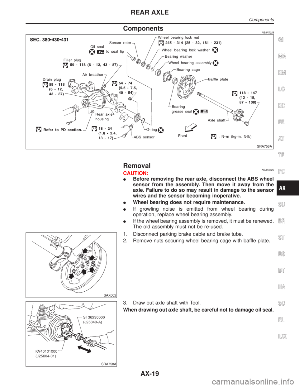
ComponentsNBAX0028
SRA756A
RemovalNBAX0029CAUTION:
IBefore removing the rear axle, disconnect the ABS wheel
sensor from the assembly. Then move it away from the
axle. Failure to do so may result in damage to the sensor
wires and the sensor becoming inoperative.
IWheel bearing does not require maintenance.
IIf growling noise is emitted from wheel bearing during
operation, replace wheel bearing assembly.
IIf the wheel bearing assembly is removed, it must be renewed.
The old assembly must not be re-used.
SAX002
1. Disconnect parking brake cable and brake tube.
2. Remove nuts securing wheel bearing cage with baffle plate.
SRA758A
3. Draw out axle shaft with Tool.
When drawing out axle shaft, be careful not to damage oil seal.
GI
MA
EM
LC
EC
FE
AT
TF
PD
SU
BR
ST
RS
BT
HA
SC
EL
IDX
REAR AXLE
Components
AX-19
Page 387 of 2395
SRA759A
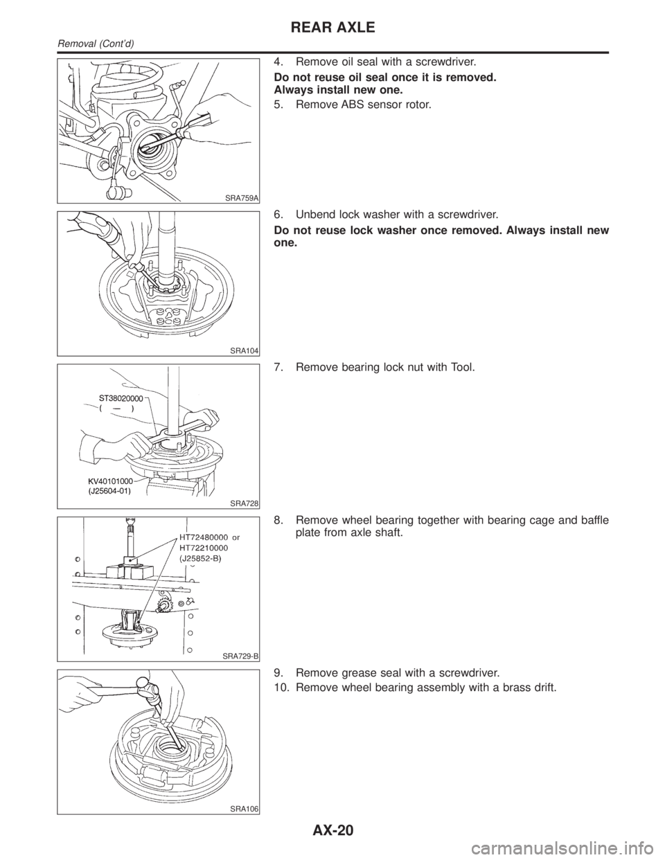
4. Remove oil seal with a screwdriver.
Do not reuse oil seal once it is removed.
Always install new one.
5. Remove ABS sensor rotor.
SRA104
6. Unbend lock washer with a screwdriver.
Do not reuse lock washer once removed. Always install new
one.
SRA728
7. Remove bearing lock nut with Tool.
SRA729-B
8. Remove wheel bearing together with bearing cage and baffle
plate from axle shaft.
SRA106
9. Remove grease seal with a screwdriver.
10. Remove wheel bearing assembly with a brass drift.
REAR AXLE
Removal (Cont'd)
AX-20
Page 388 of 2395
InspectionNBAX0030AXLE SHAFTNBAX0030S01Check axle shaft for straightness, cracks, damage, wear and dis-
tortion. Replace if necessary.
BEARING CAGENBAX0030S02Check bearing cage for deformation and cracks. Replace if neces-
sary.
REAR AXLE HOUSINGNBAX0030S03Check rear axle housing for yield, deformation and cracks. Replace
if necessary.
SRA288A
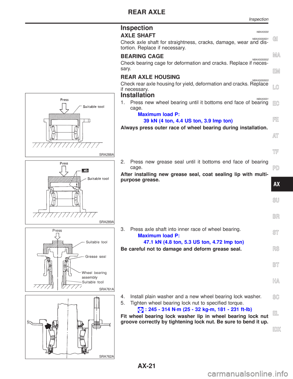
InstallationNBAX00311. Press new wheel bearing until it bottoms end face of bearing
cage.
Maximum load P:
39 kN (4 ton, 4.4 US ton, 3.9 Imp ton)
Always press outer race of wheel bearing during installation.
SRA289A
2. Press new grease seal until it bottoms end face of bearing
cage.
After installing new grease seal, coat sealing lip with multi-
purpose grease.
SRA761A
3. Press axle shaft into inner race of wheel bearing.
Maximum load P:
47.1 kN (4.8 ton, 5.3 US ton, 4.72 Imp ton)
Be careful not to damage and deform grease seal.
SRA762A
4. Install plain washer and a new wheel bearing lock washer.
5. Tighten wheel bearing lock nut to specified torque.
: 245 - 314 N´m (25 - 32 kg-m, 181 - 231 ft-lb)
Fit wheel bearing lock washer lip in wheel bearing lock nut
groove correctly by tightening lock nut. Be sure to bend it up.
GI
MA
EM
LC
EC
FE
AT
TF
PD
SU
BR
ST
RS
BT
HA
SC
EL
IDX
REAR AXLE
Inspection
AX-21
Page 389 of 2395
SRA763A
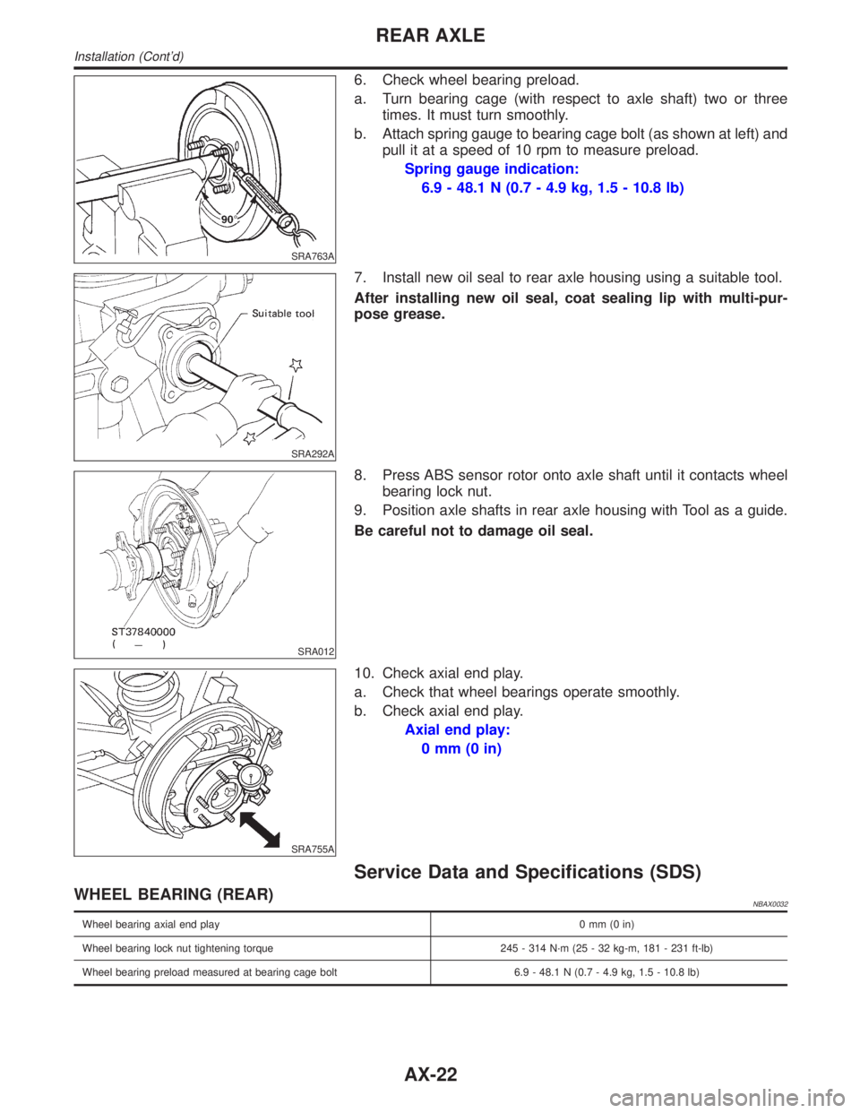
6. Check wheel bearing preload.
a. Turn bearing cage (with respect to axle shaft) two or three
times. It must turn smoothly.
b. Attach spring gauge to bearing cage bolt (as shown at left) and
pull it at a speed of 10 rpm to measure preload.
Spring gauge indication:
6.9 - 48.1 N (0.7 - 4.9 kg, 1.5 - 10.8 lb)
SRA292A
7. Install new oil seal to rear axle housing using a suitable tool.
After installing new oil seal, coat sealing lip with multi-pur-
pose grease.
SRA012
8. Press ABS sensor rotor onto axle shaft until it contacts wheel
bearing lock nut.
9. Position axle shafts in rear axle housing with Tool as a guide.
Be careful not to damage oil seal.
SRA755A
10. Check axial end play.
a. Check that wheel bearings operate smoothly.
b. Check axial end play.
Axial end play:
0mm(0in)
Service Data and Specifications (SDS)
WHEEL BEARING (REAR)NBAX0032
Wheel bearing axial end play0mm(0in)
Wheel bearing lock nut tightening torque 245 - 314 N´m (25 - 32 kg-m, 181 - 231 ft-lb)
Wheel bearing preload measured at bearing cage bolt 6.9 - 48.1 N (0.7 - 4.9 kg, 1.5 - 10.8 lb)
REAR AXLE
Installation (Cont'd)
AX-22
Page 390 of 2395

BRAKE SYSTEM
SECTION
BR
CONTENTS
PRECAUTIONS...............................................................3
Supplemental Restraint System (SRS)²AIR
BAG²and²SEAT BELT PRE-TENSIONER²...............3
Precautions for Brake System .....................................3
Wiring Diagrams and Trouble Diagnoses....................4
PREPARATION...............................................................5
Special Service Tools ..................................................5
Commercial Service Tools ...........................................5
NOISE, VIBRATION AND HARSHNESS (NVH)
TROUBLESHOOTING.....................................................6
NVH Troubleshooting Chart.........................................6
ON-VEHICLE SERVICE..................................................7
Checking Brake Fluid Level.........................................7
Checking Brake Line ...................................................7
Changing Brake Fluid ..................................................7
Bleeding Brake System ...............................................8
BRAKE HYDRAULIC LINE.............................................9
Hydraulic Circuit...........................................................9
Removal .....................................................................10
Inspection...................................................................10
Installation ..................................................................10
PROPORTIONING VALVE (2WD)................................ 11
Inspection................................................................... 11
Removal and Installation (Built-in type)..................... 11
LOAD SENSING VALVE (4WD)...................................12
Inspection...................................................................12
Removal and Installation ...........................................12
BRAKE PEDAL AND BRACKET..................................14
Removal and Installation ...........................................14
Inspection...................................................................14
Adjustment .................................................................14
MASTER CYLINDER.....................................................16
Removal .....................................................................16
Disassembly...............................................................16
Inspection...................................................................17
Assembly ...................................................................17
Installation ..................................................................18
BRAKE BOOSTER........................................................19
On-vehicle Service.....................................................19OPERATING CHECK...............................................19
AIRTIGHT CHECK...................................................19
Removal .....................................................................19
Inspection...................................................................19
OUTPUT ROD LENGTH CHECK..............................19
Installation ..................................................................20
VACUUM PIPING...........................................................21
Vacuum Hose ............................................................21
Removal and Installation ...........................................21
Inspection...................................................................21
HOSES AND CONNECTORS...................................21
CHECK VALVE........................................................21
FRONT DISC BRAKE...................................................22
Components...............................................................22
Pad Replacement ......................................................22
Removal .....................................................................23
Disassembly...............................................................24
Inspection...................................................................24
CALIPER.................................................................24
ROTOR...................................................................24
Assembly ...................................................................25
Installation ..................................................................25
Brake Burnishing Procedure......................................25
REAR DRUM BRAKE...................................................26
Components...............................................................26
Removal .....................................................................26
Inspection...................................................................27
WHEEL CYLINDER..................................................27
Wheel Cylinder Overhaul...........................................28
Inspection...................................................................28
DRUM.....................................................................28
LINING....................................................................28
Installation ..................................................................28
PARKING BRAKE CONTROL......................................30
Components...............................................................30
Removal and Installation ...........................................30
Inspection...................................................................30
Adjustment .................................................................31
GI
MA
EM
LC
EC
FE
AT
TF
PD
AX
SU
ST
RS
BT
HA
SC
EL
IDX