INFINITI QX4 2001 Factory Service Manual
Manufacturer: INFINITI, Model Year: 2001, Model line: QX4, Model: INFINITI QX4 2001Pages: 2395, PDF Size: 43.2 MB
Page 461 of 2395

2 CHECK SYMPTOM
1. Apply brake.
2. Start engine.
Does the symptom appear only when engine is started?
Ye s©Carry out self-diagnosis. Refer to BR-41, 44.
No©Go to ª3. CHECK WARNING LAMP INDICATIONº in ª2. Unexpected Pedal Actionº,
BR-70.
NOTE:
ABS may operate and cause vibration under any of the following
conditions.
IApplying brake gradually when shifting or operating clutch.
ILow friction (slippery) road.
IHigh speed cornering.
IDriving over bumps and pot holes.
IEngine speed is over 5,000 rpm with vehicle stopped.
6. Warning Lamp Does Not Come On When
Ignition Switch Is Turned On
NBBR0112
1 INSPECTION START
Warning lamp circuit inspection
SBR673E
©GO TO 2.
2 CHECK FUSE
Check 10A fuse No. 8. For fuse layout, refer to EL-16, ªPOWER SUPPLY ROUTINGº.
Is fuse OK?
Ye s©GO TO 3.
No©Replace fuse.
TROUBLE DIAGNOSES FOR SYMPTOMSABS
5. Pedal Vibration and Noise (Cont'd)
BR-72
Page 462 of 2395

3 CHECK WARNING LAMP ACTIVATE
Disconnect ABS actuator and electric unit connector.
SBR672E
Does the warning lamp activate?
Ye s©Replace ABS actuator and electric unit.
No©GO TO 4.
4 CHECK HARNESS FOR SHORT
1. Disconnect ABS actuator and electric unit connector and combination meter connector M24.
2. Check continuity between ABS actuator and electric unit connector E111 (body side) terminal 10 (2WD) or 21 (4WD)
and ground.
SBR499E
Continuity should not exist.
Does continuity exist?
Ye s©Repair harness or connectors.
No©Check combination meter.
Refer to EL-114, ªWARNING LAMPSº.
GI
MA
EM
LC
EC
FE
AT
TF
PD
AX
SU
ST
RS
BT
HA
SC
EL
IDX
TROUBLE DIAGNOSES FOR SYMPTOMSABS
6. Warning Lamp Does Not Come On When Ignition Switch Is Turned On (Cont'd)
BR-73
Page 463 of 2395

7. Warning Lamp Stays On When Ignition
Switch Is Turned On
=NBBR0113
1 INSPECTION START
ABS control unit inspection
SBR674E
©GO TO 2.
2 CHECK FUSE
Check 7.5A fuse No. 7. For fuse layout, refer to EL-16, ªPOWER SUPPLY ROUTINGº.
Is fuse OK?
Ye s©GO TO 3.
No©GO TO 8.
3 CHECK HARNESS CONNECTOR
Check ABS actuator and electric unit pin terminals for damage or bad connection of ABS actuator and electric unit harness
connector. Reconnect ABS actuator and electric unit harness connector. Then retest.
Does warning lamp stay on when ignition switch is turned ON?
Ye s©GO TO 4.
No©INSPECTION END
4 CHECK ABS ACTUATOR AND ELECTRIC UNIT GROUND CIRCUIT
Refer to ªABS ACTUATOR AND ELECTRIC UNIT GROUNDº in ªGround Circuit Checkº, BR-53.
Is ground circuit OK?
Ye s©GO TO 5.
No©Repair harness or connector.
TROUBLE DIAGNOSES FOR SYMPTOMSABS
7. Warning Lamp Stays On When Ignition Switch Is Turned On
BR-74
Page 464 of 2395

5 CHECK ABS ACTUATOR AND ELECTRIC UNIT POWER SUPPLY CIRCUIT
1. Disconnect ABS actuator and electric unit connector.
2. Check voltage between ABS actuator and electric unit connector E111 (body side) terminal 15 and ground.
SBR495E
Does battery voltage exist when ignition switch is turned ON?
Ye s©GO TO 6.
No©Check the following.
If NG, repair harness or connector.
IHarness connector E111
IHarness for open or short between ABS actuator and electric unit and fuse
6 CHECK WARNING LAMP
1. Disconnect ABS actuator and electric unit connector.
2. Connect suitable wire between ABS actuator and electric unit connector E111 (body side) terminal 10 (2WD) or 21
(4WD) and ground.
SBR502E
Does the warning lamp deactivate?
Ye s©Replace ABS actuator and electric unit.
No©GO TO 7.
GI
MA
EM
LC
EC
FE
AT
TF
PD
AX
SU
ST
RS
BT
HA
SC
EL
IDX
TROUBLE DIAGNOSES FOR SYMPTOMSABS
7. Warning Lamp Stays On When Ignition Switch Is Turned On (Cont'd)
BR-75
Page 465 of 2395
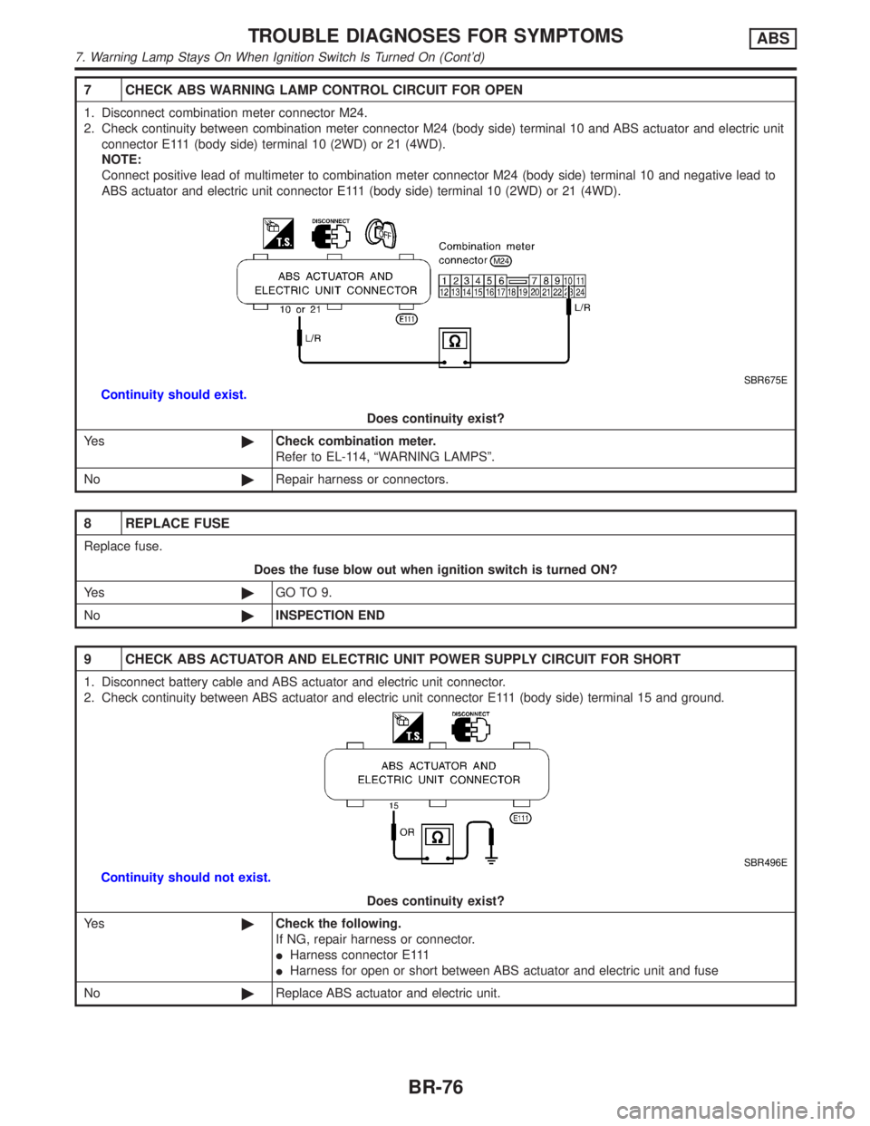
7 CHECK ABS WARNING LAMP CONTROL CIRCUIT FOR OPEN
1. Disconnect combination meter connector M24.
2. Check continuity between combination meter connector M24 (body side) terminal 10 and ABS actuator and electric unit
connector E111 (body side) terminal 10 (2WD) or 21 (4WD).
NOTE:
Connect positive lead of multimeter to combination meter connector M24 (body side) terminal 10 and negative lead to
ABS actuator and electric unit connector E111 (body side) terminal 10 (2WD) or 21 (4WD).
SBR675E
Continuity should exist.
Does continuity exist?
Ye s©Check combination meter.
Refer to EL-114, ªWARNING LAMPSº.
No©Repair harness or connectors.
8 REPLACE FUSE
Replace fuse.
Does the fuse blow out when ignition switch is turned ON?
Ye s©GO TO 9.
No©INSPECTION END
9 CHECK ABS ACTUATOR AND ELECTRIC UNIT POWER SUPPLY CIRCUIT FOR SHORT
1. Disconnect battery cable and ABS actuator and electric unit connector.
2. Check continuity between ABS actuator and electric unit connector E111 (body side) terminal 15 and ground.
SBR496E
Continuity should not exist.
Does continuity exist?
Ye s©Check the following.
If NG, repair harness or connector.
IHarness connector E111
IHarness for open or short between ABS actuator and electric unit and fuse
No©Replace ABS actuator and electric unit.
TROUBLE DIAGNOSES FOR SYMPTOMSABS
7. Warning Lamp Stays On When Ignition Switch Is Turned On (Cont'd)
BR-76
Page 466 of 2395
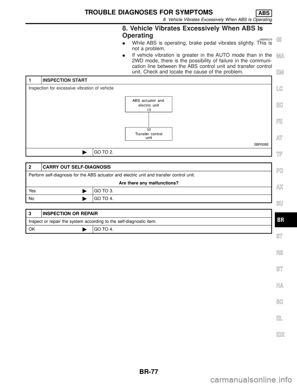
8. Vehicle Vibrates Excessively When ABS Is
Operating
=NBBR0078IWhile ABS is operating, brake pedal vibrates slightly. This is
not a problem.
IIf vehicle vibration is greater in the AUTO mode than in the
2WD mode, there is the possibility of failure in the communi-
cation line between the ABS control unit and transfer control
unit. Check and locate the cause of the problem.
1 INSPECTION START
Inspection for excessive vibration of vehicle
SBR508E
©GO TO 2.
2 CARRY OUT SELF-DIAGNOSIS
Perform self-diagnosis for the ABS actuator and electric unit and transfer control unit.
Are there any malfunctions?
Ye s©GO TO 3.
No©GO TO 4.
3 INSPECTION OR REPAIR
Inspect or repair the system according to the self-diagnostic item.
OK©GO TO 4.
GI
MA
EM
LC
EC
FE
AT
TF
PD
AX
SU
ST
RS
BT
HA
SC
EL
IDX
TROUBLE DIAGNOSES FOR SYMPTOMSABS
8. Vehicle Vibrates Excessively When ABS Is Operating
BR-77
Page 467 of 2395
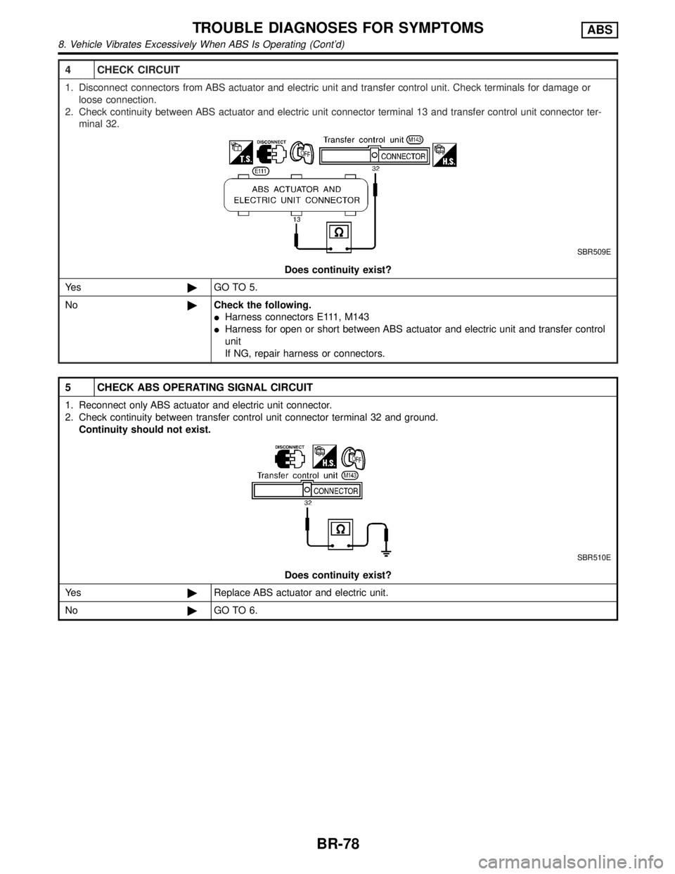
4 CHECK CIRCUIT
1. Disconnect connectors from ABS actuator and electric unit and transfer control unit. Check terminals for damage or
loose connection.
2. Check continuity between ABS actuator and electric unit connector terminal 13 and transfer control unit connector ter-
minal 32.
SBR509E
Does continuity exist?
Ye s©GO TO 5.
No©Check the following.
IHarness connectors E111, M143
IHarness for open or short between ABS actuator and electric unit and transfer control
unit
If NG, repair harness or connectors.
5 CHECK ABS OPERATING SIGNAL CIRCUIT
1. Reconnect only ABS actuator and electric unit connector.
2. Check continuity between transfer control unit connector terminal 32 and ground.
Continuity should not exist.
SBR510E
Does continuity exist?
Ye s©Replace ABS actuator and electric unit.
No©GO TO 6.
TROUBLE DIAGNOSES FOR SYMPTOMSABS
8. Vehicle Vibrates Excessively When ABS Is Operating (Cont'd)
BR-78
Page 468 of 2395
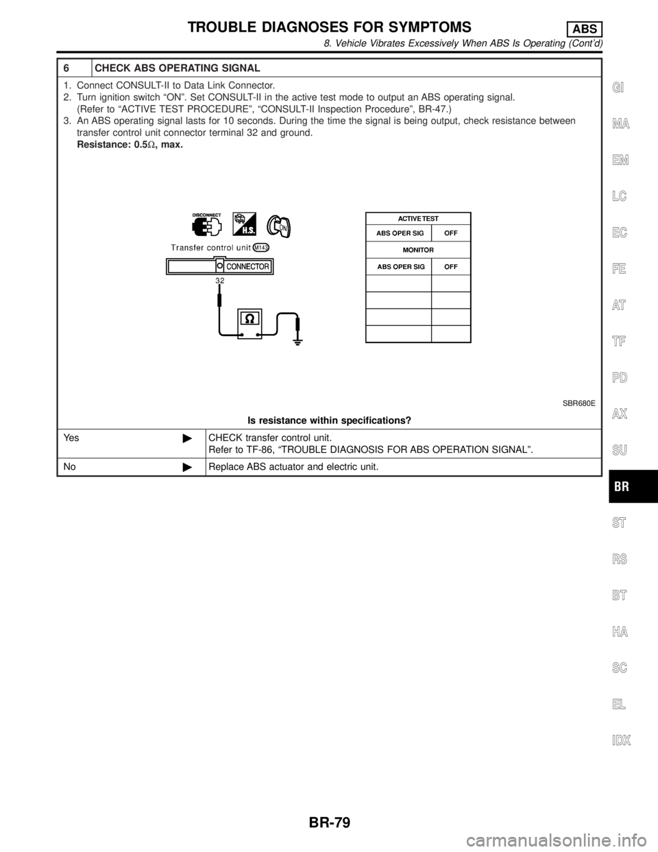
6 CHECK ABS OPERATING SIGNAL
1. Connect CONSULT-II to Data Link Connector.
2. Turn ignition switch ªONº. Set CONSULT-II in the active test mode to output an ABS operating signal.
(Refer to ªACTIVE TEST PROCEDUREº, ªCONSULT-II Inspection Procedureº, BR-47.)
3. An ABS operating signal lasts for 10 seconds. During the time the signal is being output, check resistance between
transfer control unit connector terminal 32 and ground.
Resistance: 0.5W, max.
SBR680E
Is resistance within specifications?
Ye s©CHECK transfer control unit.
Refer to TF-86, ªTROUBLE DIAGNOSIS FOR ABS OPERATION SIGNALº.
No©Replace ABS actuator and electric unit.
GI
MA
EM
LC
EC
FE
AT
TF
PD
AX
SU
ST
RS
BT
HA
SC
EL
IDX
TROUBLE DIAGNOSES FOR SYMPTOMSABS
8. Vehicle Vibrates Excessively When ABS Is Operating (Cont'd)
BR-79
Page 469 of 2395

=NBBR0079
CAUTION:
Be careful not to damage sensor edge and sensor rotor teeth.
When removing the front or rear wheel hub assembly, discon-
nect the ABS wheel sensor from the assembly and move it
away.
Front Wheel SensorNBBR0079S01
SBR398D
Rear Wheel SensorNBBR0079S02
SBR399D
REMOVAL AND INSTALLATIONABS
BR-80
Page 470 of 2395
SBR873C
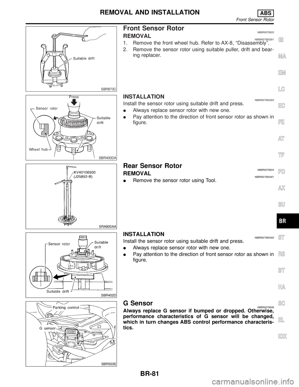
Front Sensor RotorNBBR0079S03REMOVALNBBR0079S03011. Remove the front wheel hub. Refer to AX-8, ªDisassemblyº.
2. Remove the sensor rotor using suitable puller, drift and bear-
ing replacer.
SBR400DA
INSTALLATIONNBBR0079S0302Install the sensor rotor using suitable drift and press.
IAlways replace sensor rotor with new one.
IPay attention to the direction of front sensor rotor as shown in
figure.
SRA800AA
Rear Sensor RotorNBBR0079S04REMOVALNBBR0079S0401IRemove the sensor rotor using Tool.
SBR402D
INSTALLATIONNBBR0079S0402Install the sensor rotor using suitable drift and press.
IAlways replace sensor rotor with new one.
IPay attention to the direction of front sensor rotor as shown in
figure.
SBR503E
G SensorNBBR0079S06Always replace G sensor if bumped or dropped. Otherwise,
performance characteristics of G sensor will be changed,
which in turn changes ABS control performance characteris-
tics.
GI
MA
EM
LC
EC
FE
AT
TF
PD
AX
SU
ST
RS
BT
HA
SC
EL
IDX
REMOVAL AND INSTALLATIONABS
Front Sensor Rotor
BR-81