ECO mode INFINITI QX4 2001 Factory Workshop Manual
[x] Cancel search | Manufacturer: INFINITI, Model Year: 2001, Model line: QX4, Model: INFINITI QX4 2001Pages: 2395, PDF Size: 43.2 MB
Page 594 of 2395
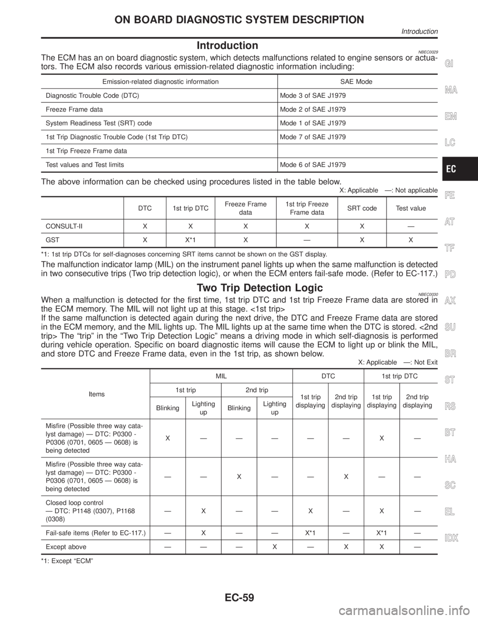
IntroductionNBEC0029The ECM has an on board diagnostic system, which detects malfunctions related to engine sensors or actua-
tors. The ECM also records various emission-related diagnostic information including:
Emission-related diagnostic information SAE Mode
Diagnostic Trouble Code (DTC) Mode 3 of SAE J1979
Freeze Frame data Mode 2 of SAE J1979
System Readiness Test (SRT) code Mode 1 of SAE J1979
1st Trip Diagnostic Trouble Code (1st Trip DTC) Mode 7 of SAE J1979
1st Trip Freeze Frame data
Test values and Test limits Mode 6 of SAE J1979
The above information can be checked using procedures listed in the table below.
X: Applicable Ð: Not applicable
DTC 1st trip DTCFreeze Frame
data1st trip Freeze
Frame dataSRT code Test value
CONSULT-II X X X X X Ð
GST X X*1 X Ð X X
*1: 1st trip DTCs for self-diagnoses concerning SRT items cannot be shown on the GST display.
The malfunction indicator lamp (MIL) on the instrument panel lights up when the same malfunction is detected
in two consecutive trips (Two trip detection logic), or when the ECM enters fail-safe mode. (Refer to EC-117.)
Two Trip Detection LogicNBEC0030When a malfunction is detected for the first time, 1st trip DTC and 1st trip Freeze Frame data are stored in
the ECM memory. The MIL will not light up at this stage. <1st trip>
If the same malfunction is detected again during the next drive, the DTC and Freeze Frame data are stored
in the ECM memory, and the MIL lights up. The MIL lights up at the same time when the DTC is stored. <2nd
trip> The ªtripº in the ªTwo Trip Detection Logicº means a driving mode in which self-diagnosis is performed
during vehicle operation. Specific on board diagnostic items will cause the ECM to light up or blink the MIL,
and store DTC and Freeze Frame data, even in the 1st trip, as shown below.
X: Applicable Ð: Not Exit
ItemsMIL DTC 1st trip DTC
1st trip 2nd trip
1st trip
displaying2nd trip
displaying1st trip
displaying2nd trip
displaying
BlinkingLighting
upBlinkingLighting
up
Misfire (Possible three way cata-
lyst damage) Ð DTC: P0300 -
P0306 (0701, 0605 Ð 0608) is
being detectedX ÐÐÐÐÐ X Ð
Misfire (Possible three way cata-
lyst damage) Ð DTC: P0300 -
P0306 (0701, 0605 Ð 0608) is
being detectedÐÐ X ÐÐ X ÐÐ
Closed loop control
Ð DTC: P1148 (0307), P1168
(0308)ÐXÐÐXÐXÐ
Fail-safe items (Refer to EC-117.) Ð X Ð Ð X*1 Ð X*1 Ð
Except above Ð Ð Ð X Ð X X Ð
*1: Except ªECMº
GI
MA
EM
LC
FE
AT
TF
PD
AX
SU
BR
ST
RS
BT
HA
SC
EL
IDX
ON BOARD DIAGNOSTIC SYSTEM DESCRIPTION
Introduction
EC-59
Page 595 of 2395
Emission-related Diagnostic InformationNBEC0031DTC AND 1ST TRIP DTCNBEC0031S01The 1st trip DTC (whose number is the same as the DTC number) is displayed for the latest self-diagnostic
result obtained. If the ECM memory was cleared previously, and the 1st trip DTC did not reoccur, the 1st trip
DTC will not be displayed.
If a malfunction is detected during the 1st trip, the 1st trip DTC is stored in the ECM memory. The MIL will not
light up (two trip detection logic). If the same malfunction is not detected in the 2nd trip (meeting the required
driving pattern), the 1st trip DTC is cleared from the ECM memory. If the same malfunction is detected in the
2nd trip, both the 1st trip DTC and DTC are stored in the ECM memory and the MIL lights up. In other words,
the DTC is stored in the ECM memory and the MIL lights up when the same malfunction occurs in two con-
secutive trips. If a 1st trip DTC is stored and a non-diagnostic operation is performed between the 1st and
2nd trips, only the 1st trip DTC will continue to be stored. For malfunctions that blink or light up the MIL dur-
ing the 1st trip, the DTC and 1st trip DTC are stored in the ECM memory.
Procedures for clearing the DTC and the 1st trip DTC from the ECM memory are described in ªHOW TO
ERASE EMISSION-RELATED DIAGNOSTIC INFORMATIONº, EC-72.
For malfunctions in which 1st trip DTCs are displayed, refer to EC-69. These items are required by legal
regulations to continuously monitor the system/component. In addition, the items monitored non-continuously
are also displayed on CONSULT-II.
1st trip DTC is specified in Mode 7 of SAE J1979. 1st trip DTC detection occurs without lighting up the MIL
and therefore does not warn the driver of a problem. However, 1st trip DTC detection will not prevent the
vehicle from being tested, for example during Inspection/Maintenance (I/M) tests.
When a 1st trip DTC is detected, check, print out or write down and erase (1st trip) DTC and Freeze Frame
data as specified in ªWork Flowº procedure Step II, refer to EC-99. Then perform ªDTC Confirmation Proce-
dureº or ªOverall Function Checkº to try to duplicate the problem. If the malfunction is duplicated, the item
requires repair.
How to Read DTC and 1st Trip DTCNBEC0031S0101DTC and 1st trip DTC can be read by the following methods.
With CONSULT-II
With GST
CONSULT-II or GST (Generic Scan Tool) Examples: P0340, P1320, P0705, P0750, etc.
These DTCs are prescribed by SAE J2012.
(CONSULT-II also displays the malfunctioning component or system.)
I1st trip DTC No. is the same as DTC No.
IOutput of a DTC indicates a malfunction. However, GST does not indicate whether the malfunction
is still occurring or has occurred in the past and has returned to normal. CONSULT-II can identify
malfunction status as shown below. Therefore, using CONSULT-II (if available) is recommended.
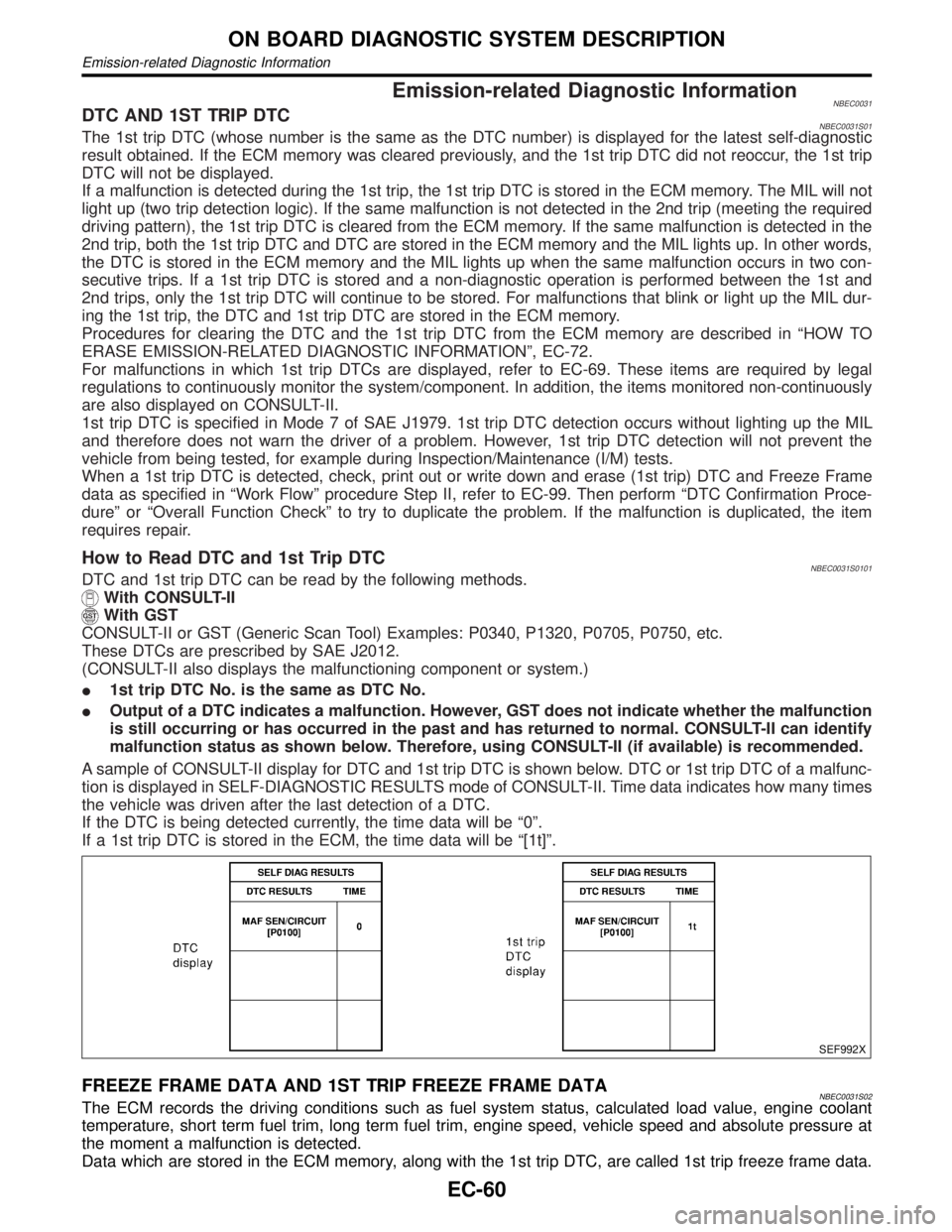
A sample of CONSULT-II display for DTC and 1st trip DTC is shown below. DTC or 1st trip DTC of a malfunc-
tion is displayed in SELF-DIAGNOSTIC RESULTS mode of CONSULT-II. Time data indicates how many times
the vehicle was driven after the last detection of a DTC.
If the DTC is being detected currently, the time data will be ª0º.
If a 1st trip DTC is stored in the ECM, the time data will be ª[1t]º.
SEF992X
FREEZE FRAME DATA AND 1ST TRIP FREEZE FRAME DATANBEC0031S02The ECM records the driving conditions such as fuel system status, calculated load value, engine coolant
temperature, short term fuel trim, long term fuel trim, engine speed, vehicle speed and absolute pressure at
the moment a malfunction is detected.
Data which are stored in the ECM memory, along with the 1st trip DTC, are called 1st trip freeze frame data.
ON BOARD DIAGNOSTIC SYSTEM DESCRIPTION
Emission-related Diagnostic Information
EC-60
Page 602 of 2395
IThe time required for each diagnosis varies with road surface conditions, weather, altitude, individual driv-
ing habits, etc.
Zone A refers to the range where the time required, for the diagnosis under normal conditions*, is the
shortest.
Zone B refers to the range where the diagnosis can still be performed if the diagnosis is not completed
within zone A.
*: Normal conditions refer to the following:
þ Sea level
þ Flat road
þ Ambient air temperature: 20 - 30ÉC (68 - 86ÉF)
þ Diagnosis is performed as quickly as possible under normal conditions.
Under different conditions [For example: ambient air temperature other than 20 - 30ÉC (68 - 86ÉF)], diag-
nosis may also be performed.
Pattern 1:
IThe engine is started at the engine coolant temperature of þ10 to 35ÉC (14 to 95ÉF)
(where the voltage between the ECM terminal 70 and ground is 3.0 - 4.3V).
IThe engine must be operated at idle speed until the engine coolant temperature is greater than 70ÉC
(158ÉF) (where the voltage between the ECM terminal 70 and ground is lower than 1.4V).
IThe engine is started at the fuel tank temperature of warmer than 0ÉC (32ÉF) (where the voltage
between the ECM terminal 92 and ground is less than 4.1V).
Pattern 2:
IWhen steady-state driving is performed again even after it is interrupted, each diagnosis can be conducted.
In this case, the time required for diagnosis may be extended.
Pattern 3:
IThe driving pattern outlined in *2 must be repeated at least 3 times.
Pattern 4:
ITests are performed after the engine has been operated for at least 17 minutes.
IThe accelerator pedal must be held very steady during steady-state driving.
IIf the accelerator pedal is moved, the test must be conducted all over again.
*1: Depress the accelerator pedal until vehicle speed is 90 km/h (56 MPH), then release the accelerator pedal
and keep it released for more than 10 seconds. Depress the accelerator pedal until vehicle speed is 90 km/h
(56 MPH) again.
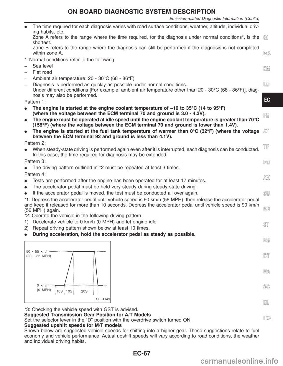
*2: Operate the vehicle in the following driving pattern.
1) Decelerate vehicle to 0 km/h (0 MPH) and let engine idle.
2) Repeat driving pattern shown below at least 10 times.
IDuring acceleration, hold the accelerator pedal as steady as possible.
SEF414S
*3: Checking the vehicle speed with GST is advised.
Suggested Transmission Gear Position for A/T Models
Set the selector lever in the ªDº position with the overdrive switch turned ON.
Suggested upshift speeds for M/T models
Shown below are suggested vehicle speeds for shifting into a higher gear. These suggestions relate to fuel
economy and vehicle performance. Actual upshift speeds will vary according to road conditions, the weather
and individual driving habits.
GI
MA
EM
LC
FE
AT
TF
PD
AX
SU
BR
ST
RS
BT
HA
SC
EL
IDX
ON BOARD DIAGNOSTIC SYSTEM DESCRIPTION
Emission-related Diagnostic Information (Cont'd)
EC-67
Page 607 of 2395

Items
(CONSULT-II screen terms)DTC*1 SRT codeTest value/ Test
limit
(GST only)1st trip DTC*1 Reference page
INTK TIM S/CIRC-B2 P1145 Ð Ð X EC-482
CLOSED LOOP-B1 P1148 Ð Ð X EC-491
SWL CON VC SW/CIRC P1165 Ð Ð X EC-493
CLOSED LOOP-B2 P1168 Ð Ð X EC-491
ENG OVER TEMP P1217 Ð Ð X LC-24
IGN SIGNAL-PRIMARY P1320 Ð Ð X EC-499
CPS/CIRCUIT (REF) P1335 Ð Ð X EC-510
CPS/CIRC (POS) COG P1336 Ð Ð X EC-517
EVAP VERY SMALL LEAK P1441 X X X*2 EC-526
PURG VOLUME CONT/V P1444 Ð Ð X EC-541
VENT CONTROL VALVE P1446 Ð Ð X EC-553
EVAP PURG FLOW/MON P1447 X X X*2 EC-561
VENT CONTROL VALVE P1448 Ð Ð X EC-573
FUEL LEVEL SEN/CIRC P1464 Ð Ð X EC-582
VC/V BYPASS/V P1490 Ð Ð X EC-585
VC CUT/V BYPASS/V P1491 Ð Ð X EC-591
A/T DIAG COMM LINE P1605 Ð Ð X EC-603
TP SEN/CIRC A/T P1705 Ð Ð X AT-218
P-N POS SW/CIRCUIT P1706 Ð Ð X EC-604
O/R CLTCH SOL/CIRC P1760 Ð Ð X AT-223
*1: 1st trip DTC No. is the same as DTC No.
*2: These are not displayed with GST.
NOTE:
Regarding R50 models, ª-B1º and ªBK1º indicate right bank and ª-B2º and ªBK2º indicate left bank.
HOW TO ERASE EMISSION-RELATED DIAGNOSTIC INFORMATIONNBEC0031S06How to Erase DTC (With CONSULT-II)NBEC0031S0601NOTE:
If the DTC is not for A/T related items (see EC-8), skip steps 2 through 4.
1. If the ignition switch stays ªONº after repair work, be sure to turn ignition switch ªOFFº once. Wait at least
10 seconds and then turn it ªONº (engine stopped) again.
2. Turn CONSULT-II ªONº and touch ªA/Tº.
3. Touch ªSELF-DIAG RESULTSº.
4. Touch ªERASEº. [The DTC in the TCM (Transmission control module) will be erased.] Then touch ªBACKº
twice.
5. Touch ªENGINEº.
6. Touch ªSELF-DIAG RESULTSº.
7. Touch ªERASEº. (The DTC in the ECM will be erased.)
IIf DTCs are displayed for both ECM and TCM (Transmission control module), they need to be erased
individually from the ECM and TCM (Transmission control module).
ON BOARD DIAGNOSTIC SYSTEM DESCRIPTION
Emission-related Diagnostic Information (Cont'd)
EC-72
Page 608 of 2395

SEF823YA
The emission related diagnostic information in the ECM can be erased by selecting ªERASEº in the ªSELF-
DIAG RESULTSº mode with CONSULT-II.
How to Erase DTC (With GST)NBEC0031S0602NOTE:
If the DTC is not for A/T related items (see EC-8), skip step 2.
1. If the ignition switch stays ªONº after repair work, be sure to turn ignition switch ªOFFº once. Wait at least
10 seconds and then turn it ªONº (engine stopped) again.
2. Perform ªSELF-DIAGNOSTIC PROCEDURE (Without CONSULT-II)º in AT section titled ªTROUBLE
DIAGNOSISº, ªSelf-diagnosisº. (The engine warm-up step can be skipped when performing the diagnosis
only to erase the DTC.)
3. Select Mode 4 with GST (Generic Scan Tool).
The emission related diagnostic information in the ECM can be erased by selecting Mode 4 with GST.
IIf the battery is disconnected, the emission-related diagnostic information will be lost after approx.
24 hours.
IThe following data are cleared when the ECM memory is erased.
1) Diagnostic trouble codes
2) 1st trip diagnostic trouble codes
3) Freeze frame data
4) 1st trip freeze frame data
5) System readiness test (SRT) codes
6) Test values
7) Others
GI
MA
EM
LC
FE
AT
TF
PD
AX
SU
BR
ST
RS
BT
HA
SC
EL
IDX
ON BOARD DIAGNOSTIC SYSTEM DESCRIPTION
Emission-related Diagnostic Information (Cont'd)
EC-73
Page 610 of 2395
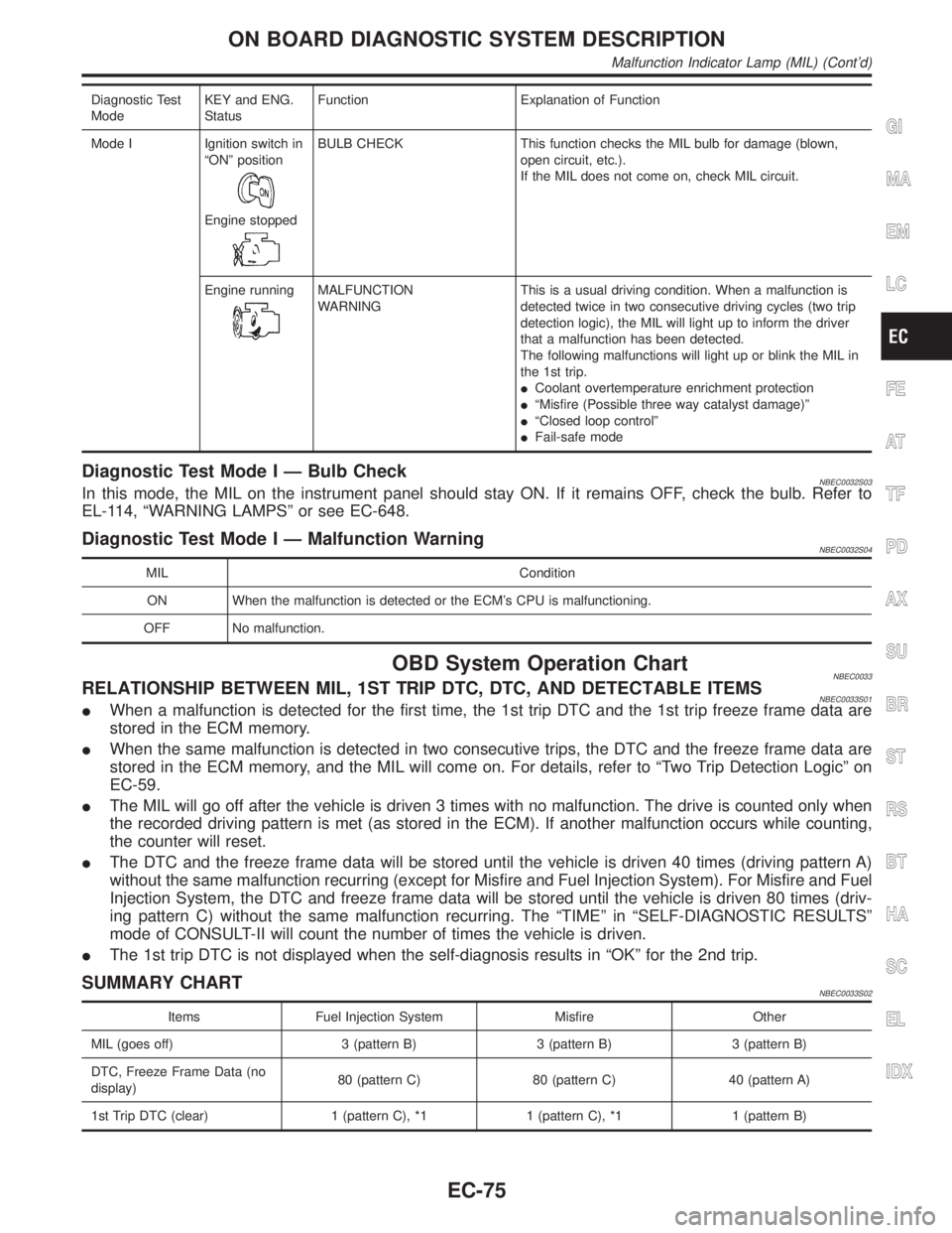
Diagnostic Test
ModeKEY and ENG.
StatusFunction Explanation of Function
Mode I Ignition switch in
ªONº position
Engine stopped
BULB CHECK This function checks the MIL bulb for damage (blown,
open circuit, etc.).
If the MIL does not come on, check MIL circuit.
Engine running
MALFUNCTION
WARNINGThis is a usual driving condition. When a malfunction is
detected twice in two consecutive driving cycles (two trip
detection logic), the MIL will light up to inform the driver
that a malfunction has been detected.
The following malfunctions will light up or blink the MIL in
the 1st trip.
ICoolant overtemperature enrichment protection
IªMisfire (Possible three way catalyst damage)º
IªClosed loop controlº
IFail-safe mode
Diagnostic Test Mode I Ð Bulb CheckNBEC0032S03In this mode, the MIL on the instrument panel should stay ON. If it remains OFF, check the bulb. Refer to
EL-114, ªWARNING LAMPSº or see EC-648.
Diagnostic Test Mode I Ð Malfunction WarningNBEC0032S04
MIL Condition
ON When the malfunction is detected or the ECM's CPU is malfunctioning.
OFF No malfunction.
OBD System Operation ChartNBEC0033RELATIONSHIP BETWEEN MIL, 1ST TRIP DTC, DTC, AND DETECTABLE ITEMSNBEC0033S01IWhen a malfunction is detected for the first time, the 1st trip DTC and the 1st trip freeze frame data are
stored in the ECM memory.
IWhen the same malfunction is detected in two consecutive trips, the DTC and the freeze frame data are
stored in the ECM memory, and the MIL will come on. For details, refer to ªTwo Trip Detection Logicº on
EC-59.
IThe MIL will go off after the vehicle is driven 3 times with no malfunction. The drive is counted only when
the recorded driving pattern is met (as stored in the ECM). If another malfunction occurs while counting,
the counter will reset.
IThe DTC and the freeze frame data will be stored until the vehicle is driven 40 times (driving pattern A)
without the same malfunction recurring (except for Misfire and Fuel Injection System). For Misfire and Fuel
Injection System, the DTC and freeze frame data will be stored until the vehicle is driven 80 times (driv-
ing pattern C) without the same malfunction recurring. The ªTIMEº in ªSELF-DIAGNOSTIC RESULTSº
mode of CONSULT-II will count the number of times the vehicle is driven.
IThe 1st trip DTC is not displayed when the self-diagnosis results in ªOKº for the 2nd trip.
SUMMARY CHARTNBEC0033S02
Items Fuel Injection System Misfire Other
MIL (goes off) 3 (pattern B) 3 (pattern B) 3 (pattern B)
DTC, Freeze Frame Data (no
display)80 (pattern C) 80 (pattern C) 40 (pattern A)
1st Trip DTC (clear) 1 (pattern C), *1 1 (pattern C), *1 1 (pattern B)
GI
MA
EM
LC
FE
AT
TF
PD
AX
SU
BR
ST
RS
BT
HA
SC
EL
IDX
ON BOARD DIAGNOSTIC SYSTEM DESCRIPTION
Malfunction Indicator Lamp (MIL) (Cont'd)
EC-75
Page 622 of 2395
![INFINITI QX4 2001 Factory Workshop Manual DATA MONITOR MODE=NBEC0034S06
Monitored item [Unit]ECM
input
signalsMain
signalsDescription Remarks
ENG SPEED [rpm]qqIIndicates the engine speed computed
from the REF signal (120É signal) of the
cran INFINITI QX4 2001 Factory Workshop Manual DATA MONITOR MODE=NBEC0034S06
Monitored item [Unit]ECM
input
signalsMain
signalsDescription Remarks
ENG SPEED [rpm]qqIIndicates the engine speed computed
from the REF signal (120É signal) of the
cran](/img/42/57027/w960_57027-621.png)
DATA MONITOR MODE=NBEC0034S06
Monitored item [Unit]ECM
input
signalsMain
signalsDescription Remarks
ENG SPEED [rpm]qqIIndicates the engine speed computed
from the REF signal (120É signal) of the
crankshaft position sensor (REF).
CKPS´RPM (POS)
[rpm]qIIndicates the engine speed computed
from the POS signal (1É signal) of the
crankshaft position sensor (POS).IAccuracy becomes poor if engine
speed drops below the idle rpm.
IIf the signal is interrupted while the
engine is running, an abnormal value
may be indicated.
POS COUNTqIIndicates the number of signal plate
(Flywheel/Drive Plate) cogs (tooth) dur-
ing one revolution of the engine.
MAS A/F SE-B1 [V]qqIThe signal voltage of the mass air flow
sensor is displayed.IWhen the engine is stopped, a certain
value is indicated.
COOLAN TEMP/S
[ÉC] or [ÉF]qqIThe engine coolant temperature (deter-
mined by the signal voltage of the
engine coolant temperature sensor) is
displayed.IWhen the engine coolant temperature
sensor is open or short-circuited, ECM
enters fail-safe mode. The engine cool-
ant temperature determined by the
ECM is displayed.
HO2S1 (B1) [V]qq
IThe signal voltage of the front heated
oxygen sensor is displayed.
HO2S1 (B2) [V]qq
HO2S2 (B1) [V]qq
IThe signal voltage of the rear heated
oxygen sensor is displayed.
HO2S2 (B2) [V]qq
HO2S1 MNTR (B1)
[RICH/LEAN]qIDisplay of front heated oxygen sensor
signal during air-fuel ratio feedback
control:
RICH ... means the mixture became
ªrichº, and control is being affected
toward a leaner mixture.
LEAN ... means the mixture became
ªleanº, and control is being affected
toward a rich mixture.IAfter turning ON the ignition switch,
ªRICHº is displayed until air-fuel mixture
ratio feedback control begins.
IWhen the air-fuel ratio feedback is
clamped, the value just before the
clamping is displayed continuously. HO2S1 MNTR (B2)
[RICH/LEAN]q
HO2S2 MNTR (B1)
[RICH/LEAN]qIDisplay of rear heated oxygen sensor
signal:
RICH ... means the amount of oxygen
after three way catalyst is relatively
small.
LEAN ... means the amount of oxygen
after three way catalyst is relatively
large.IWhen the engine is stopped, a certain
value is indicated.
HO2S2 MNTR (B2)
[RICH/LEAN]q
VHCL SPEED SE
[km/h] or [mph]qqIThe vehicle speed computed from the
vehicle speed sensor signal is dis-
played.
BATTERY VOLT [V]qqIThe power supply voltage of ECM is
displayed.
THRTL POS SEN [V]qqIThe throttle position sensor signal volt-
age is displayed.
FUEL T/TMP SE
[ÉC] or [ÉF]IThe fuel temperature judged from the
tank fuel temperature sensor signal
voltage is displayed.GI
MA
EM
LC
FE
AT
TF
PD
AX
SU
BR
ST
RS
BT
HA
SC
EL
IDX
ON BOARD DIAGNOSTIC SYSTEM DESCRIPTION
CONSULT-II (Cont'd)
EC-87
Page 628 of 2395

DTC Work Support ModeNBEC0034S0802
Test mode Test item Condition Reference page
EVAPORATIVE SYSTEMEVAP SML LEAK P0440
Refer to corresponding
trouble diagnosis for
DTC.EC-352
EVAP VERY SML LEAK P1441 EC-526
PURG VOL CN/V P1444 EC-541
PURGE FLOW P1447 EC-561
VC CUT/V BP/V P1491 EC-591
HEATED OXYGEN SEN-
SOR 1 (FRONT)HO2S1 (B1) P0130 EC-192
HO2S1 (B1) P0131 EC-202
HO2S1 (B1) P0132 EC-210
HO2S1 (B1) P0133 EC-218
HO2S1 (B2) P0150 EC-192
HO2S1 (B2) P0151 EC-202
HO2S1 (B2) P0152 EC-210
HO2S1 (B2) P0153 EC-218
HEATED OXYGEN SEN-
SOR 2 (REAR)HO2S2 (B1) P0137 EC-247
HO2S2 (B1) P0138 EC-257
HO2S2 (B1) P0139 EC-267
HO2S2 (B2) P0157 EC-247
HO2S2 (B2) P0158 EC-257
HO2S2 (B2) P0159 EC-267
SEF705Y
SEF707X
REAL TIME DIAGNOSIS IN DATA MONITOR MODE
(RECORDING VEHICLE DATA)
NBEC0034S10CONSULT-II has two kinds of triggers and they can be selected by
touching ªSETTINGº in ªDATA MONITORº mode.
1) ªAUTO TRIGº (Automatic trigger):
IThe malfunction will be identified on the CONSULT-II screen in
real time.
In other words, DTC/1st trip DTC and malfunction item will be
displayed if the malfunction is detected by ECM.
At the moment a malfunction is detected by ECM, ªMONITORº
in ªDATA MONITORº screen is changed to ªRecording Data ...
xx%º as shown at left, and the data after the malfunction detec-
tion is recorded. Then when the percentage reached 100%,
ªREAL-TIME DIAGº screen is displayed. If ªSTOPº is touched
on the screen during ª Recording Data ... xx%º, ªREAL-TIME
DIAGº screen is also displayed.
The recording time after the malfunction detection and the
recording speed can be changed by ªTRIGGER POINTº and
ªRecording Speedº. Refer to CONSULT-II OPERATION
MANUAL.
2) ªMANU TRIGº (Manual trigger):
IDTC/1st trip DTC and malfunction item will not be displayed
GI
MA
EM
LC
FE
AT
TF
PD
AX
SU
BR
ST
RS
BT
HA
SC
EL
IDX
ON BOARD DIAGNOSTIC SYSTEM DESCRIPTION
CONSULT-II (Cont'd)
EC-93
Page 643 of 2395
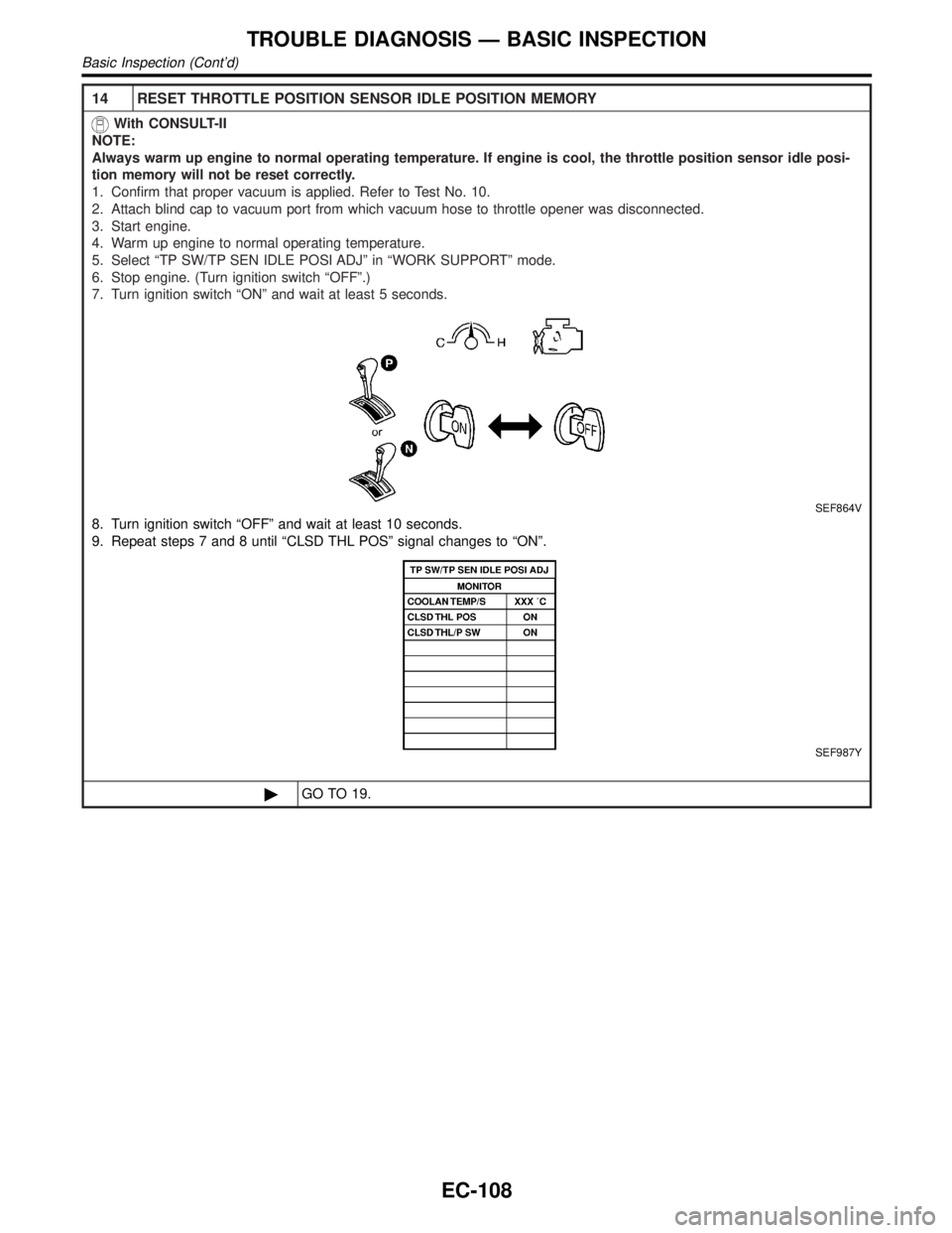
14 RESET THROTTLE POSITION SENSOR IDLE POSITION MEMORY
With CONSULT-II
NOTE:
Always warm up engine to normal operating temperature. If engine is cool, the throttle position sensor idle posi-
tion memory will not be reset correctly.
1. Confirm that proper vacuum is applied. Refer to Test No. 10.
2. Attach blind cap to vacuum port from which vacuum hose to throttle opener was disconnected.
3. Start engine.
4. Warm up engine to normal operating temperature.
5. Select ªTP SW/TP SEN IDLE POSI ADJº in ªWORK SUPPORTº mode.
6. Stop engine. (Turn ignition switch ªOFFº.)
7. Turn ignition switch ªONº and wait at least 5 seconds.
SEF864V
8. Turn ignition switch ªOFFº and wait at least 10 seconds.
9. Repeat steps 7 and 8 until ªCLSD THL POSº signal changes to ªONº.
SEF987Y
©GO TO 19.
TROUBLE DIAGNOSIS Ð BASIC INSPECTION
Basic Inspection (Cont'd)
EC-108
Page 657 of 2395

SYMPTOM
Reference
section
HARD/NO START/RESTART (EXCP. HA)
ENGINE STALL
HESITATION/SURGING/FLAT SPOT
SPARK KNOCK/DETONATION
LACK OF POWER/POOR ACCELERATION
HIGH IDLE/LOW IDLE
ROUGH IDLE/HUNTING
IDLING VIBRATION
SLOW/NO RETURN TO IDLE
OVERHEATS/WATER TEMPERATURE HIGH
EXCESSIVE FUEL CONSUMPTION
EXCESSIVE OIL CONSUMPTION
BATTERY DEAD (UNDER CHARGE)
Warranty symptom code AA AB AC AD AE AF AG AH AJ AK AL AM HA
IVIS (INFINITI Vehicle Immobilizer System Ð
NATS)11EC-74 or EL
section
1 - 6: The numbers refer to the order of inspection.
CONSULT-II Reference Value in Data Monitor
Mode
NBEC0042Remarks:
ISpecification data are reference values.
ISpecification data are output/input values which are detected or supplied by the ECM at the connector.
* Specification data may not be directly related to their components signals/values/operations.
i.e. Adjust ignition timing with a timing light before monitoring IGN TIMING, because the monitor may show the specification data in
spite of the ignition timing not being adjusted to the specification data. This IGN TIMING monitors the data calculated by the ECM
according to the signals input from the camshaft position sensor and other ignition timing related sensors.
IIf the real-time diagnosis results are NG and the on board diagnostic system results are OK when diagnosing the mass air flow sensor,
first check to see if the fuel pump control circuit is normal.
MONITOR ITEM CONDITION SPECIFICATION
ENG SPEED
CKPS´RPM (POS)ITachometer: Connect
IRun engine and compare tachometer indication with the CONSULT-II
value.Almost the same speed as
the CONSULT-II value.
POS COUNTIEngine: Running 179 - 181
MAS A/F SE-B1IEngine: After warming up
IAir conditioner switch: ªOFFº
IShift lever: ªNº
INo-loadIdle 1.2 - 1.8V
2,500 rpm 1.6 - 2.2V
COOLAN TEMP/SIEngine: After warming up More than 70ÉC (158ÉF)
HO2S1 (B1)
HO2S1 (B2)
IEngine: After warming upMaintaining engine speed at 2,000
rpm0 - 0.3V+,Approx. 0.6 -
1.0V
HO2S1 MNTR (B1)
HO2S1 MNTR (B2)LEAN+,RICH
Changes more than 5 times
during 10 seconds.
HO2S2 (B1)
HO2S2 (B2)
IEngine: After warming upMaintaining engine speed at 2,000
rpm0 - 0.3V+,Approx. 0.6 -
1.0V
HO2S2 MNTR (B1)
HO2S2 MNTR (B2)LEAN+,RICH
TROUBLE DIAGNOSIS Ð GENERAL DESCRIPTION
Symptom Matrix Chart (Cont'd)
EC-122