Ac system INFINITI QX4 2001 Factory Service Manual
[x] Cancel search | Manufacturer: INFINITI, Model Year: 2001, Model line: QX4, Model: INFINITI QX4 2001Pages: 2395, PDF Size: 43.2 MB
Page 1804 of 2395
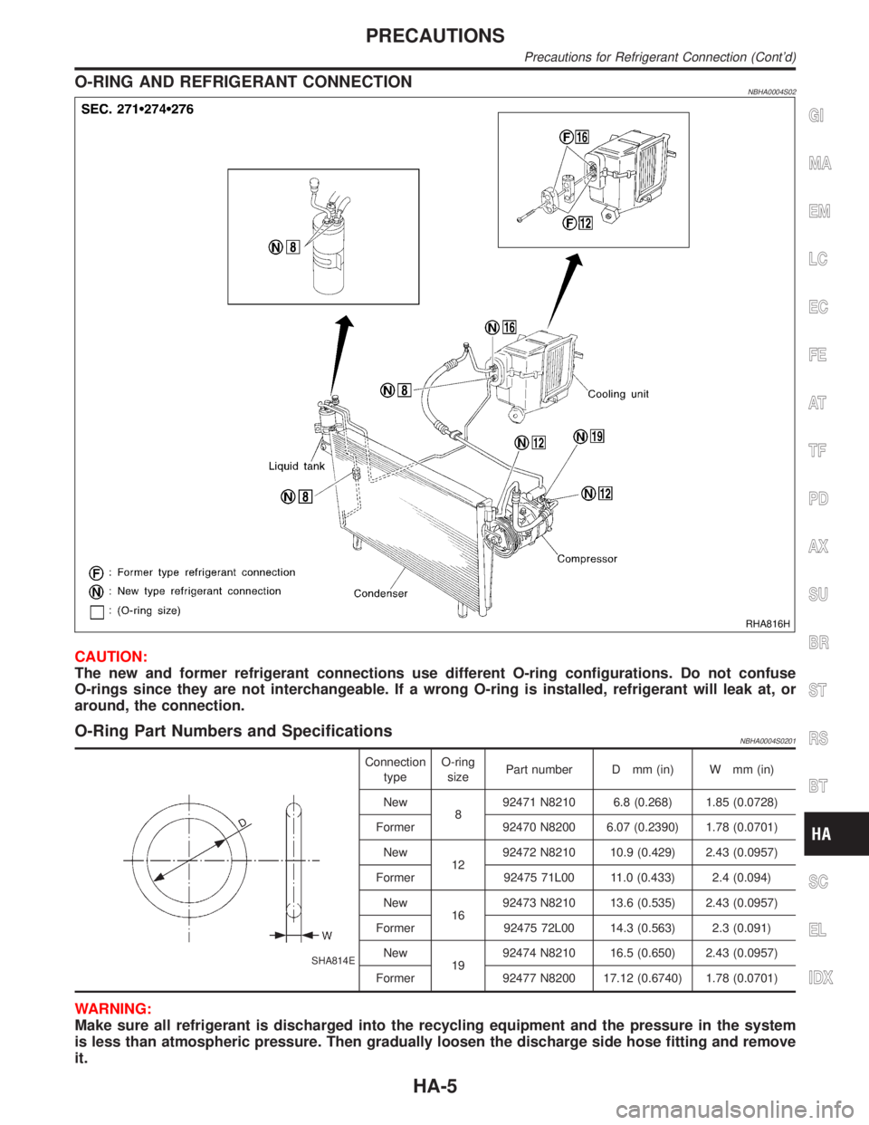
O-RING AND REFRIGERANT CONNECTIONNBHA0004S02
RHA816H
CAUTION:
The new and former refrigerant connections use different O-ring configurations. Do not confuse
O-rings since they are not interchangeable. If a wrong O-ring is installed, refrigerant will leak at, or
around, the connection.
O-Ring Part Numbers and SpecificationsNBHA0004S0201
SHA814E
Connection
typeO-ring
sizePart number D mm (in) W mm (in)
New
892471 N8210 6.8 (0.268) 1.85 (0.0728)
Former 92470 N8200 6.07 (0.2390) 1.78 (0.0701)
New
1292472 N8210 10.9 (0.429) 2.43 (0.0957)
Former 92475 71L00 11.0 (0.433) 2.4 (0.094)
New
1692473 N8210 13.6 (0.535) 2.43 (0.0957)
Former 92475 72L00 14.3 (0.563) 2.3 (0.091)
New
1992474 N8210 16.5 (0.650) 2.43 (0.0957)
Former 92477 N8200 17.12 (0.6740) 1.78 (0.0701)
WARNING:
Make sure all refrigerant is discharged into the recycling equipment and the pressure in the system
is less than atmospheric pressure. Then gradually loosen the discharge side hose fitting and remove
it.
GI
MA
EM
LC
EC
FE
AT
TF
PD
AX
SU
BR
ST
RS
BT
SC
EL
IDX
PRECAUTIONS
Precautions for Refrigerant Connection (Cont'd)
HA-5
Page 1805 of 2395
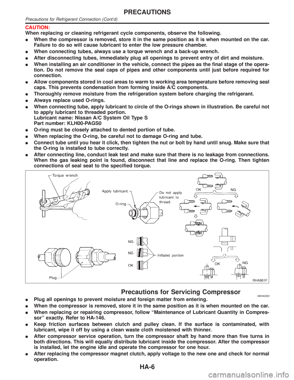
CAUTION:
When replacing or cleaning refrigerant cycle components, observe the following.
IWhen the compressor is removed, store it in the same position as it is when mounted on the car.
Failure to do so will cause lubricant to enter the low pressure chamber.
IWhen connecting tubes, always use a torque wrench and a back-up wrench.
IAfter disconnecting tubes, immediately plug all openings to prevent entry of dirt and moisture.
IWhen installing an air conditioner in the vehicle, connect the pipes as the final stage of the opera-
tion. Do not remove the seal caps of pipes and other components until just before required for
connection.
IAllow components stored in cool areas to warm to working area temperature before removing seal
caps. This prevents condensation from forming inside A/C components.
IThoroughly remove moisture from the refrigeration system before charging the refrigerant.
IAlways replace used O-rings.
IWhen connecting tube, apply lubricant to circle of the O-rings shown in illustration. Be careful not
to apply lubricant to threaded portion.
Lubricant name: Nissan A/C System Oil Type S
Part number: KLH00-PAGS0
IO-ring must be closely attached to dented portion of tube.
IWhen replacing the O-ring, be careful not to damage O-ring and tube.
IConnect tube until you hear it click, then tighten the nut or bolt by hand until snug. Make sure that
the O-ring is installed to tube correctly.
IAfter connecting line, conduct leak test and make sure that there is no leakage from connections.
When the gas leaking point is found, disconnect that line and replace the O-ring. Then tighten
connections of seal seat to the specified torque.
RHA861F
Precautions for Servicing CompressorNBHA0005IPlug all openings to prevent moisture and foreign matter from entering.
IWhen the compressor is removed, store it in the same position as it is when mounted on the car.
IWhen replacing or repairing compressor, follow ªMaintenance of Lubricant Quantity in Compres-
sorº exactly. Refer to HA-146.
IKeep friction surfaces between clutch and pulley clean. If the surface is contaminated, with
lubricant, wipe it off by using a clean waste cloth moistened with thinner.
IAfter compressor service operation, turn the compressor shaft by hand more than five turns in
both directions. This will equally distribute lubricant inside the compressor. After the compressor
is installed, let the engine idle and operate the compressor for one hour.
IAfter replacing the compressor magnet clutch, apply voltage to the new one and check for normal
operation.
PRECAUTIONS
Precautions for Refrigerant Connection (Cont'd)
HA-6
Page 1806 of 2395
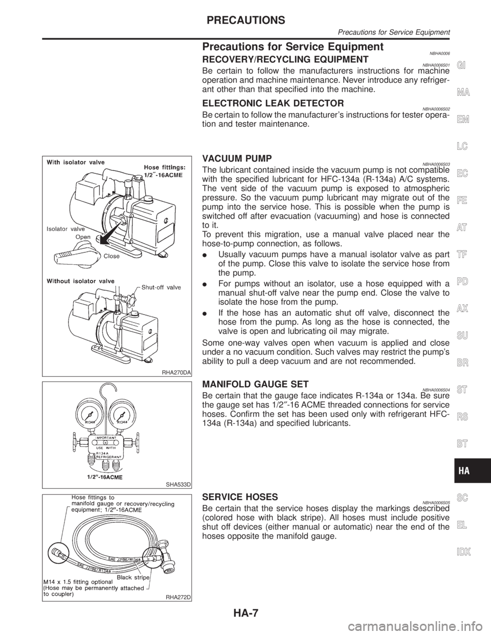
Precautions for Service EquipmentNBHA0006RECOVERY/RECYCLING EQUIPMENTNBHA0006S01Be certain to follow the manufacturers instructions for machine
operation and machine maintenance. Never introduce any refriger-
ant other than that specified into the machine.
ELECTRONIC LEAK DETECTORNBHA0006S02Be certain to follow the manufacturer's instructions for tester opera-
tion and tester maintenance.
RHA270DA
VACUUM PUMPNBHA0006S03The lubricant contained inside the vacuum pump is not compatible
with the specified lubricant for HFC-134a (R-134a) A/C systems.
The vent side of the vacuum pump is exposed to atmospheric
pressure. So the vacuum pump lubricant may migrate out of the
pump into the service hose. This is possible when the pump is
switched off after evacuation (vacuuming) and hose is connected
to it.
To prevent this migration, use a manual valve placed near the
hose-to-pump connection, as follows.
IUsually vacuum pumps have a manual isolator valve as part
of the pump. Close this valve to isolate the service hose from
the pump.
IFor pumps without an isolator, use a hose equipped with a
manual shut-off valve near the pump end. Close the valve to
isolate the hose from the pump.
IIf the hose has an automatic shut off valve, disconnect the
hose from the pump. As long as the hose is connected, the
valve is open and lubricating oil may migrate.
Some one-way valves open when vacuum is applied and close
under a no vacuum condition. Such valves may restrict the pump's
ability to pull a deep vacuum and are not recommended.
SHA533D
MANIFOLD GAUGE SETNBHA0006S04Be certain that the gauge face indicates R-134a or 134a. Be sure
the gauge set has 1/2²-16 ACME threaded connections for service
hoses. Confirm the set has been used only with refrigerant HFC-
134a (R-134a) and specified lubricants.
RHA272D
SERVICE HOSESNBHA0006S05Be certain that the service hoses display the markings described
(colored hose with black stripe). All hoses must include positive
shut off devices (either manual or automatic) near the end of the
hoses opposite the manifold gauge.
GI
MA
EM
LC
EC
FE
AT
TF
PD
AX
SU
BR
ST
RS
BT
SC
EL
IDX
PRECAUTIONS
Precautions for Service Equipment
HA-7
Page 1807 of 2395
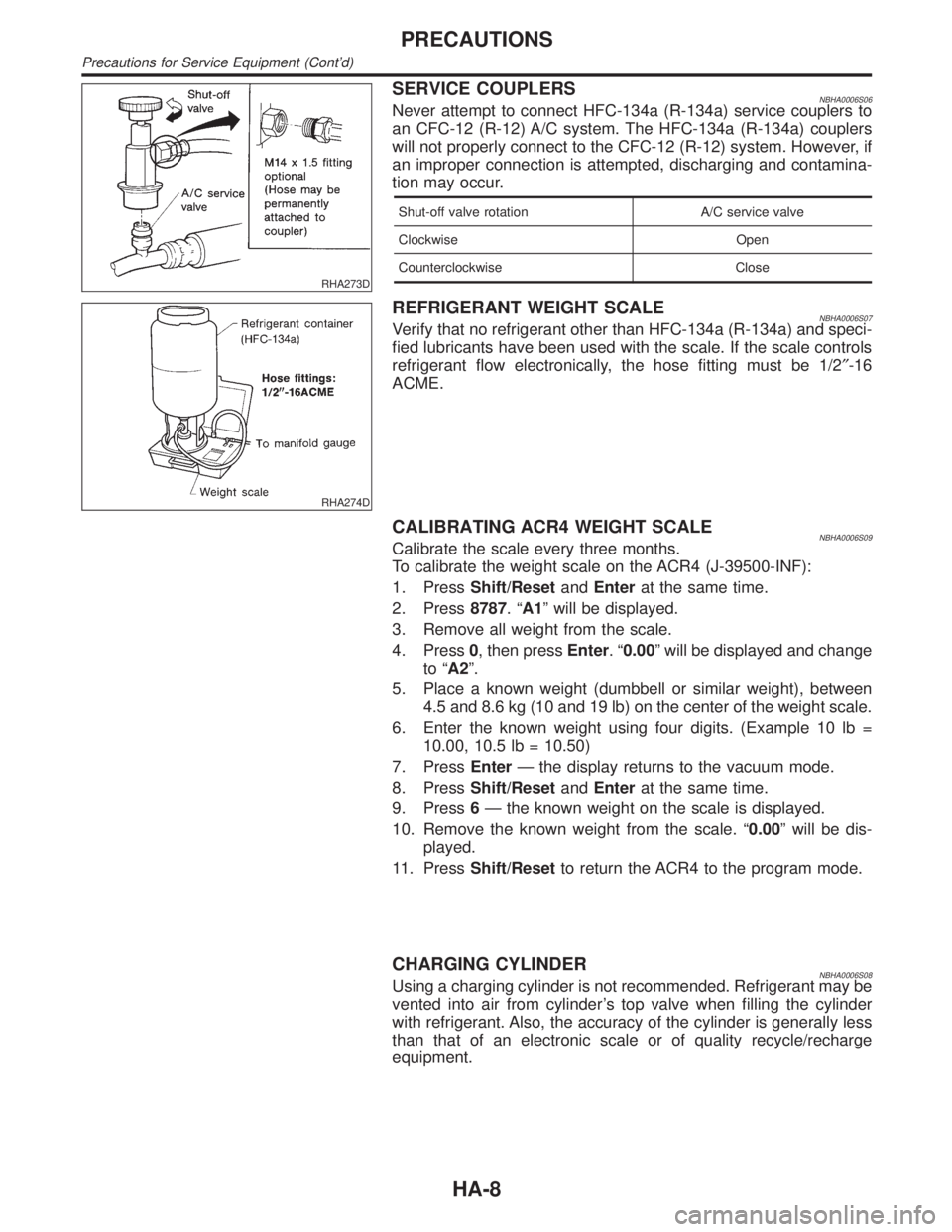
RHA273D
SERVICE COUPLERSNBHA0006S06Never attempt to connect HFC-134a (R-134a) service couplers to
an CFC-12 (R-12) A/C system. The HFC-134a (R-134a) couplers
will not properly connect to the CFC-12 (R-12) system. However, if
an improper connection is attempted, discharging and contamina-
tion may occur.
Shut-off valve rotation A/C service valve
Clockwise Open
Counterclockwise Close
RHA274D
REFRIGERANT WEIGHT SCALENBHA0006S07Verify that no refrigerant other than HFC-134a (R-134a) and speci-
fied lubricants have been used with the scale. If the scale controls
refrigerant flow electronically, the hose fitting must be 1/2²-16
ACME.
CALIBRATING ACR4 WEIGHT SCALENBHA0006S09Calibrate the scale every three months.
To calibrate the weight scale on the ACR4 (J-39500-INF):
1. PressShift/ResetandEnterat the same time.
2. Press8787.ªA1º will be displayed.
3. Remove all weight from the scale.
4. Press0, then pressEnter.ª0.00º will be displayed and change
to ªA2º.
5. Place a known weight (dumbbell or similar weight), between
4.5 and 8.6 kg (10 and 19 lb) on the center of the weight scale.
6. Enter the known weight using four digits. (Example 10 lb =
10.00, 10.5 lb = 10.50)
7. PressEnterÐ the display returns to the vacuum mode.
8. PressShift/ResetandEnterat the same time.
9. Press6Ð the known weight on the scale is displayed.
10. Remove the known weight from the scale. ª0.00º will be dis-
played.
11. PressShift/Resetto return the ACR4 to the program mode.
CHARGING CYLINDERNBHA0006S08Using a charging cylinder is not recommended. Refrigerant may be
vented into air from cylinder's top valve when filling the cylinder
with refrigerant. Also, the accuracy of the cylinder is generally less
than that of an electronic scale or of quality recycle/recharge
equipment.
PRECAUTIONS
Precautions for Service Equipment (Cont'd)
HA-8
Page 1810 of 2395
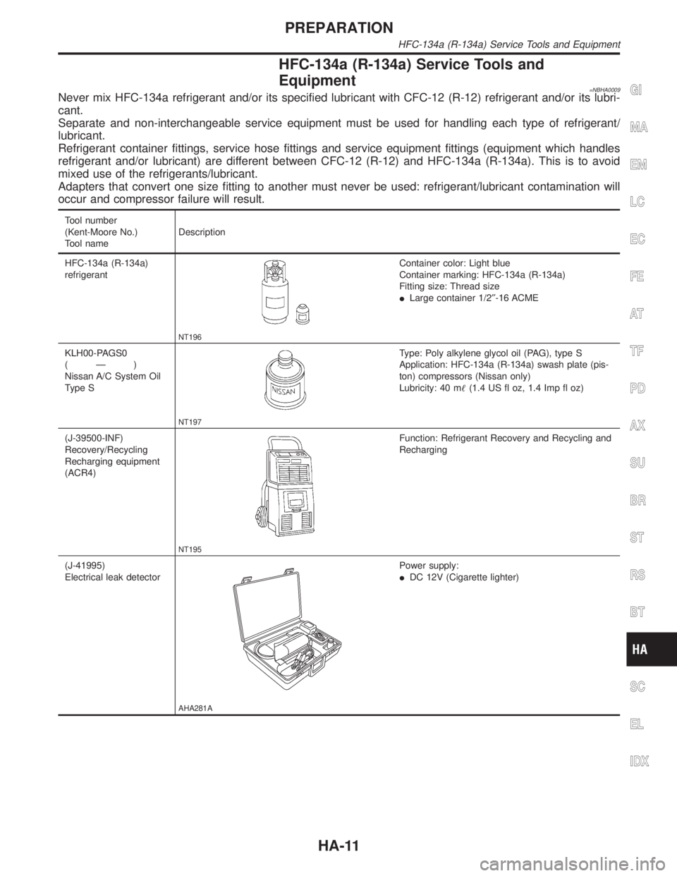
HFC-134a (R-134a) Service Tools and
Equipment
=NBHA0009Never mix HFC-134a refrigerant and/or its specified lubricant with CFC-12 (R-12) refrigerant and/or its lubri-
cant.
Separate and non-interchangeable service equipment must be used for handling each type of refrigerant/
lubricant.
Refrigerant container fittings, service hose fittings and service equipment fittings (equipment which handles
refrigerant and/or lubricant) are different between CFC-12 (R-12) and HFC-134a (R-134a). This is to avoid
mixed use of the refrigerants/lubricant.
Adapters that convert one size fitting to another must never be used: refrigerant/lubricant contamination will
occur and compressor failure will result.
Tool number
(Kent-Moore No.)
Tool nameDescription
HFC-134a (R-134a)
refrigerant
NT196
Container color: Light blue
Container marking: HFC-134a (R-134a)
Fitting size: Thread size
ILarge container 1/2²-16 ACME
KLH00-PAGS0
(Ð)
Nissan A/C System Oil
Type S
NT197
Type: Poly alkylene glycol oil (PAG), type S
Application: HFC-134a (R-134a) swash plate (pis-
ton) compressors (Nissan only)
Lubricity: 40 m(1.4 US fl oz, 1.4 Imp fl oz)
(J-39500-INF)
Recovery/Recycling
Recharging equipment
(ACR4)
NT195
Function: Refrigerant Recovery and Recycling and
Recharging
(J-41995)
Electrical leak detector
AHA281A
Power supply:
IDC 12V (Cigarette lighter)
GI
MA
EM
LC
EC
FE
AT
TF
PD
AX
SU
BR
ST
RS
BT
SC
EL
IDX
PREPARATION
HFC-134a (R-134a) Service Tools and Equipment
HA-11
Page 1811 of 2395
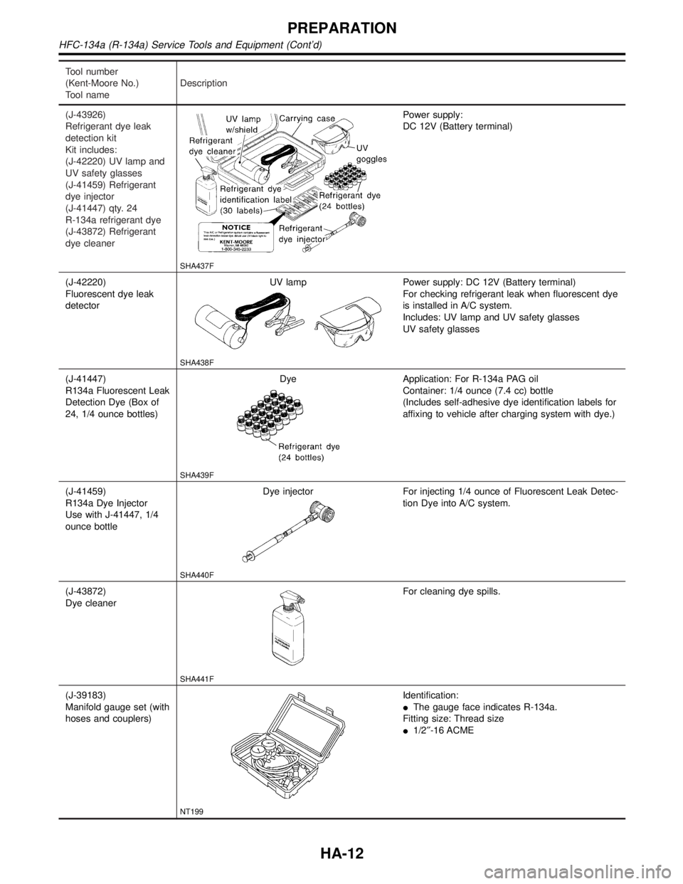
Tool number
(Kent-Moore No.)
Tool nameDescription
(J-43926)
Refrigerant dye leak
detection kit
Kit includes:
(J-42220) UV lamp and
UV safety glasses
(J-41459) Refrigerant
dye injector
(J-41447) qty. 24
R-134a refrigerant dye
(J-43872) Refrigerant
dye cleaner
SHA437F
Power supply:
DC 12V (Battery terminal)
(J-42220)
Fluorescent dye leak
detectorUV lamp
SHA438F
Power supply: DC 12V (Battery terminal)
For checking refrigerant leak when fluorescent dye
is installed in A/C system.
Includes: UV lamp and UV safety glasses
UV safety glasses
(J-41447)
R134a Fluorescent Leak
Detection Dye (Box of
24, 1/4 ounce bottles)Dye
SHA439F
Application: For R-134a PAG oil
Container: 1/4 ounce (7.4 cc) bottle
(Includes self-adhesive dye identification labels for
affixing to vehicle after charging system with dye.)
(J-41459)
R134a Dye Injector
Use with J-41447, 1/4
ounce bottleDye injector
SHA440F
For injecting 1/4 ounce of Fluorescent Leak Detec-
tion Dye into A/C system.
(J-43872)
Dye cleaner
SHA441F
For cleaning dye spills.
(J-39183)
Manifold gauge set (with
hoses and couplers)
NT199
Identification:
IThe gauge face indicates R-134a.
Fitting size: Thread size
I1/2²-16 ACME
PREPARATION
HFC-134a (R-134a) Service Tools and Equipment (Cont'd)
HA-12
Page 1812 of 2395
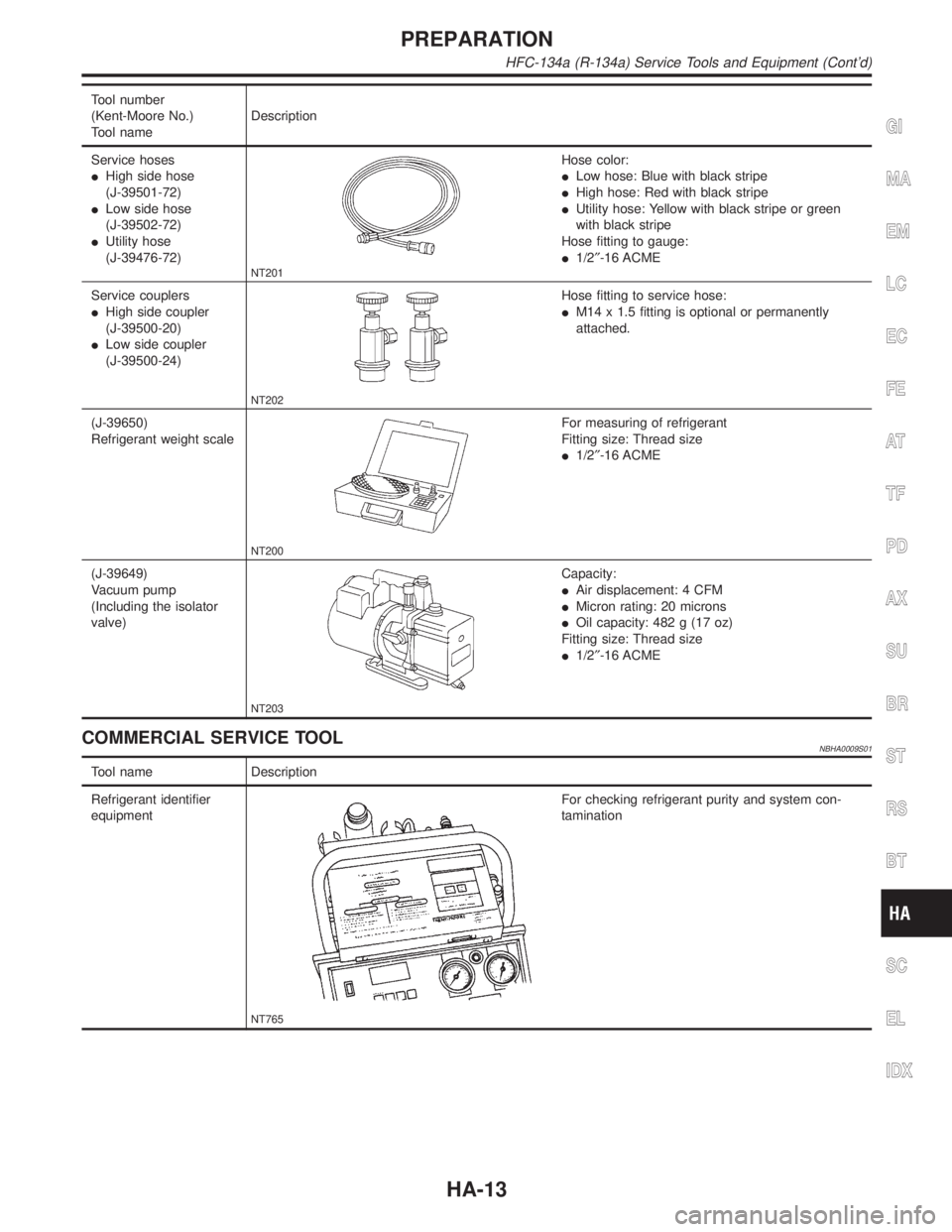
Tool number
(Kent-Moore No.)
Tool nameDescription
Service hoses
IHigh side hose
(J-39501-72)
ILow side hose
(J-39502-72)
IUtility hose
(J-39476-72)
NT201
Hose color:
ILow hose: Blue with black stripe
IHigh hose: Red with black stripe
IUtility hose: Yellow with black stripe or green
with black stripe
Hose fitting to gauge:
I1/2²-16 ACME
Service couplers
IHigh side coupler
(J-39500-20)
ILow side coupler
(J-39500-24)
NT202
Hose fitting to service hose:
IM14 x 1.5 fitting is optional or permanently
attached.
(J-39650)
Refrigerant weight scale
NT200
For measuring of refrigerant
Fitting size: Thread size
I1/2²-16 ACME
(J-39649)
Vacuum pump
(Including the isolator
valve)
NT203
Capacity:
IAir displacement: 4 CFM
IMicron rating: 20 microns
IOil capacity: 482 g (17 oz)
Fitting size: Thread size
I1/2²-16 ACME
COMMERCIAL SERVICE TOOLNBHA0009S01
Tool name Description
Refrigerant identifier
equipment
NT765
For checking refrigerant purity and system con-
tamination
GI
MA
EM
LC
EC
FE
AT
TF
PD
AX
SU
BR
ST
RS
BT
SC
EL
IDX
PREPARATION
HFC-134a (R-134a) Service Tools and Equipment (Cont'd)
HA-13
Page 1813 of 2395
Refrigeration System
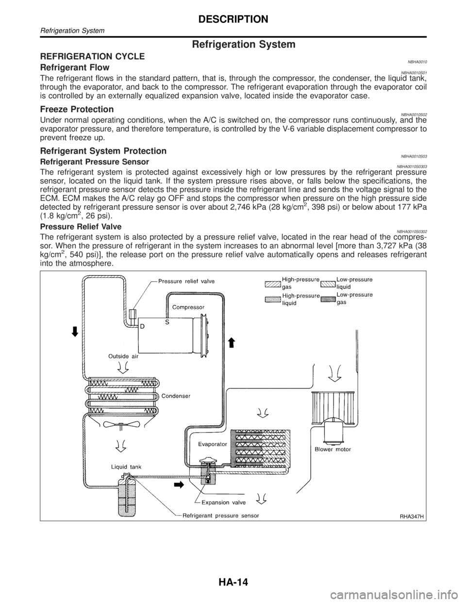
REFRIGERATION CYCLENBHA0010Refrigerant FlowNBHA0010S01The refrigerant flows in the standard pattern, that is, through the compressor, the condenser, the liquid tank,
through the evaporator, and back to the compressor. The refrigerant evaporation through the evaporator coil
is controlled by an externally equalized expansion valve, located inside the evaporator case.
Freeze ProtectionNBHA0010S02Under normal operating conditions, when the A/C is switched on, the compressor runs continuously, and the
evaporator pressure, and therefore temperature, is controlled by the V-6 variable displacement compressor to
prevent freeze up.
Refrigerant System ProtectionNBHA0010S03Refrigerant Pressure SensorNBHA0010S0303The refrigerant system is protected against excessively high or low pressures by the refrigerant pressure
sensor, located on the liquid tank. If the system pressure rises above, or falls below the specifications, the
refrigerant pressure sensor detects the pressure inside the refrigerant line and sends the voltage signal to the
ECM. ECM makes the A/C relay go OFF and stops the compressor when pressure on the high pressure side
detected by refrigerant pressure sensor is over about 2,746 kPa (28 kg/cm
2, 398 psi) or below about 177 kPa
(1.8 kg/cm2, 26 psi).
Pressure Relief Valve
NBHA0010S0302The refrigerant system is also protected by a pressure relief valve, located in the rear head of the compres-
sor. When the pressure of refrigerant in the system increases to an abnormal level [more than 3,727 kPa (38
kg/cm
2, 540 psi)], the release port on the pressure relief valve automatically opens and releases refrigerant
into the atmosphere.
RHA347H
DESCRIPTION
Refrigeration System
HA-14
Page 1814 of 2395
V-6 Variable Displacement Compressor
GENERAL INFORMATION=NBHA00861. The V-6 variable compressor differs from previous units. The vent temperatures of the V-6 variable com-
press do not drop too far below 5ÉC (41ÉF) when:
Ievaporator intake air temperature is less than 20ÉC (68ÉF)
Iengine is running at speeds less than 1,500 rpm.
This is because the V-6 compressor provides a means of ªcapacityº control.
2. The V-6 variable compressor provides refrigerant control under varying conditions. During cold winters, it
may not produce high refrigerant pressure discharge (compared to previous units) when used with air
conditioning systems.
3. A ªclankingº sound may occasionally be heard during refrigerant charge. The sound indicates that the tilt
angle of the swash plate has changed and is not a problem.
4. For air conditioning systems with the V-6 compressor, the clutch remains engaged unless: the system main
switch, fan switch or ignition switch is turned OFF. When ambient (outside) temperatures are low or when
the amount of refrigerant is insufficient, the clutch is disengaged to protect the compressor.
5. A constant range of suction pressure is maintained when engine speed is greater than a certain value. It
normally ranges from 147 to 177 kPa (1.5 to 1.8 kg/cm
2, 21 to 26 psi) under varying conditions.
In previous compressors, however, suction pressure was reduced with increases in engine speed.
GI
MA
EM
LC
EC
FE
AT
TF
PD
AX
SU
BR
ST
RS
BT
SC
EL
IDX
DESCRIPTION
V-6 Variable Displacement Compressor
HA-15
Page 1819 of 2395
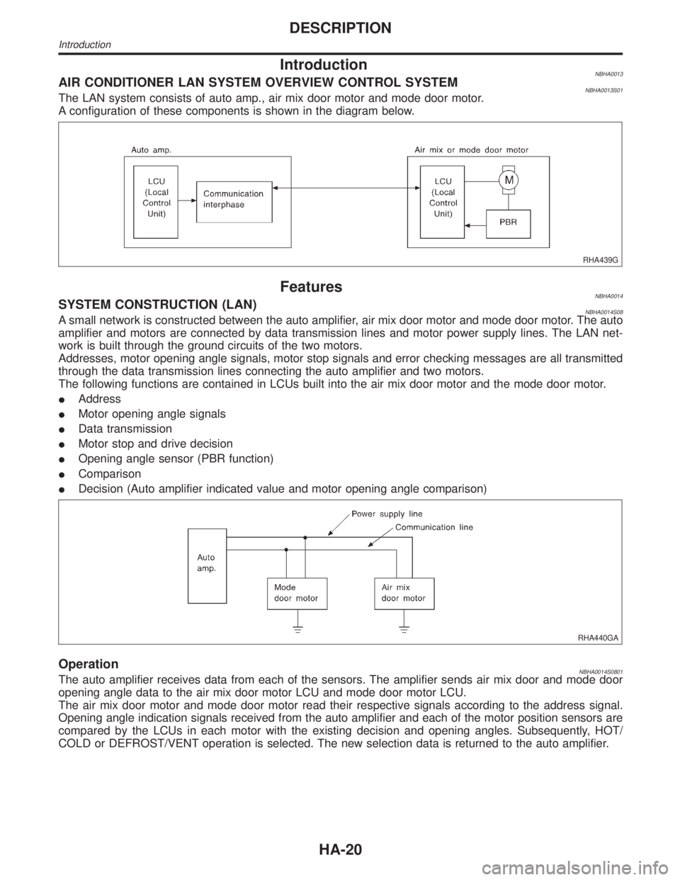
IntroductionNBHA0013AIR CONDITIONER LAN SYSTEM OVERVIEW CONTROL SYSTEMNBHA0013S01The LAN system consists of auto amp., air mix door motor and mode door motor.
A configuration of these components is shown in the diagram below.
RHA439G
FeaturesNBHA0014SYSTEM CONSTRUCTION (LAN)NBHA0014S08A small network is constructed between the auto amplifier, air mix door motor and mode door motor. The auto
amplifier and motors are connected by data transmission lines and motor power supply lines. The LAN net-
work is built through the ground circuits of the two motors.
Addresses, motor opening angle signals, motor stop signals and error checking messages are all transmitted
through the data transmission lines connecting the auto amplifier and two motors.
The following functions are contained in LCUs built into the air mix door motor and the mode door motor.
IAddress
IMotor opening angle signals
IData transmission
IMotor stop and drive decision
IOpening angle sensor (PBR function)
IComparison
IDecision (Auto amplifier indicated value and motor opening angle comparison)
RHA440GA
OperationNBHA0014S0801The auto amplifier receives data from each of the sensors. The amplifier sends air mix door and mode door
opening angle data to the air mix door motor LCU and mode door motor LCU.
The air mix door motor and mode door motor read their respective signals according to the address signal.
Opening angle indication signals received from the auto amplifier and each of the motor position sensors are
compared by the LCUs in each motor with the existing decision and opening angles. Subsequently, HOT/
COLD or DEFROST/VENT operation is selected. The new selection data is returned to the auto amplifier.
DESCRIPTION
Introduction
HA-20