IDX INFINITI QX4 2001 Factory Service Manual
[x] Cancel search | Manufacturer: INFINITI, Model Year: 2001, Model line: QX4, Model: INFINITI QX4 2001Pages: 2395, PDF Size: 43.2 MB
Page 1812 of 2395

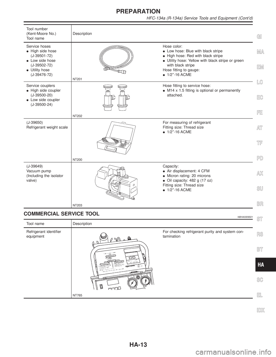
Tool number
(Kent-Moore No.)
Tool nameDescription
Service hoses
IHigh side hose
(J-39501-72)
ILow side hose
(J-39502-72)
IUtility hose
(J-39476-72)
NT201
Hose color:
ILow hose: Blue with black stripe
IHigh hose: Red with black stripe
IUtility hose: Yellow with black stripe or green
with black stripe
Hose fitting to gauge:
I1/2²-16 ACME
Service couplers
IHigh side coupler
(J-39500-20)
ILow side coupler
(J-39500-24)
NT202
Hose fitting to service hose:
IM14 x 1.5 fitting is optional or permanently
attached.
(J-39650)
Refrigerant weight scale
NT200
For measuring of refrigerant
Fitting size: Thread size
I1/2²-16 ACME
(J-39649)
Vacuum pump
(Including the isolator
valve)
NT203
Capacity:
IAir displacement: 4 CFM
IMicron rating: 20 microns
IOil capacity: 482 g (17 oz)
Fitting size: Thread size
I1/2²-16 ACME
COMMERCIAL SERVICE TOOLNBHA0009S01
Tool name Description
Refrigerant identifier
equipment
NT765
For checking refrigerant purity and system con-
tamination
GI
MA
EM
LC
EC
FE
AT
TF
PD
AX
SU
BR
ST
RS
BT
SC
EL
IDX
PREPARATION
HFC-134a (R-134a) Service Tools and Equipment (Cont'd)
HA-13
Page 1814 of 2395

V-6 Variable Displacement Compressor
GENERAL INFORMATION=NBHA00861. The V-6 variable compressor differs from previous units. The vent temperatures of the V-6 variable com-
press do not drop too far below 5ÉC (41ÉF) when:
Ievaporator intake air temperature is less than 20ÉC (68ÉF)
Iengine is running at speeds less than 1,500 rpm.
This is because the V-6 compressor provides a means of ªcapacityº control.
2. The V-6 variable compressor provides refrigerant control under varying conditions. During cold winters, it
may not produce high refrigerant pressure discharge (compared to previous units) when used with air
conditioning systems.
3. A ªclankingº sound may occasionally be heard during refrigerant charge. The sound indicates that the tilt
angle of the swash plate has changed and is not a problem.
4. For air conditioning systems with the V-6 compressor, the clutch remains engaged unless: the system main
switch, fan switch or ignition switch is turned OFF. When ambient (outside) temperatures are low or when
the amount of refrigerant is insufficient, the clutch is disengaged to protect the compressor.
5. A constant range of suction pressure is maintained when engine speed is greater than a certain value. It
normally ranges from 147 to 177 kPa (1.5 to 1.8 kg/cm
2, 21 to 26 psi) under varying conditions.
In previous compressors, however, suction pressure was reduced with increases in engine speed.
GI
MA
EM
LC
EC
FE
AT
TF
PD
AX
SU
BR
ST
RS
BT
SC
EL
IDX
DESCRIPTION
V-6 Variable Displacement Compressor
HA-15
Page 1816 of 2395

Operation=NBHA0087S021. Operation Control ValveNBHA0087S0201Operation control valve is located in the suction port (low-pressure) side, and opens or closes in response to
changes in refrigerant suction pressure.
Operation of the valve controls the internal pressure of the crankcase.
The angle of the swash plate is controlled between the crankcase's internal pressure and the piston cylinder
pressure.
2. Maximum Cooling
NBHA0087S0202Refrigerant pressure on the low-pressure side increases with an increase in heat loads.
When this occurs, the control valve's bellows compress to open the low-pressure side valve and close the
high-pressure side valve.
This causes the following pressure changes:
Ithe crankcase's internal pressure to equal the pressure on the low-pressure side;
Ithe cylinder's internal pressure to be greater than the crankcase's internal pressure.
Under this condition, the swash plate is set to the maximum stroke position.
RHA473C
GI
MA
EM
LC
EC
FE
AT
TF
PD
AX
SU
BR
ST
RS
BT
SC
EL
IDX
DESCRIPTION
V-6 Variable Displacement Compressor (Cont'd)
HA-17
Page 1818 of 2395

Component LayoutNBHA0012
RHA451G
GI
MA
EM
LC
EC
FE
AT
TF
PD
AX
SU
BR
ST
RS
BT
SC
EL
IDX
DESCRIPTION
Component Layout
HA-19
Page 1820 of 2395

RHA441GA
Transmission Data and Transmission OrderNBHA0014S0802Amplifier data is transmitted consecutively to each of the door motors following the form shown in figure below.
Start: Initial compulsory signal sent to each of the door motors.
Address: Data sent from the auto amplifier is selected according to data-based decisions made by the air mix
door motor and mode door motor.
If the addresses are identical, the opening angle data and error check signals are received by the door motor
LCUs. The LCUs then make the appropriate error decision. If the opening angle data is normal, door control
begins.
If an error exists, the received data is rejected and corrected data received. Finally, door control is based upon
the corrected opening angle data.
Opening angle: Data that shows the indicated door opening angle of each door motor.
Error check: Procedure by which sent and received data is checked for errors. Error data is then compiled.
The error check prevents corrupted data from being used by the air mix door motor and mode door motor.
Error data can be related to the following problems.
IAbnormal electrical frequency
IPoor electrical connections
ISignal leakage from transmission lines
ISignal level fluctuation
Stop signal: At the end of each transmission, a stop operation, in-operation, or internal problem message is
delivered to the auto amplifier. This completes one data transmission and control cycle.
RHA442G
Air Mix Door Control (Automatic Temperature Control)NBHA0014S0803The air mix door is automatically controlled so that in-vehicle temperature is maintained at a predetermined
value by: The temperature setting, ambient temperature, in-vehicle temperature and amount of sunload.
GI
MA
EM
LC
EC
FE
AT
TF
PD
AX
SU
BR
ST
RS
BT
SC
EL
IDX
DESCRIPTION
Features (Cont'd)
HA-21
Page 1822 of 2395

Overview of Control System=NBHA0015The control system consists of input sensors, switches, the automatic amplifier (microcomputer) and outputs.
The relationship of these components is shown in the diagram below:
RHA856H
Control OperationNBHA0016
RHA452GA
GI
MA
EM
LC
EC
FE
AT
TF
PD
AX
SU
BR
ST
RS
BT
SC
EL
IDX
DESCRIPTION
Overview of Control System
HA-23
Page 1824 of 2395

Discharge Air FlowNBHA0017
RHA043G
GI
MA
EM
LC
EC
FE
AT
TF
PD
AX
SU
BR
ST
RS
BT
SC
EL
IDX
DESCRIPTION
Discharge Air Flow
HA-25
Page 1826 of 2395

Component LocationNBHA0033ENGINE COMPARTMENTNBHA0033S01
SHA281FA
GI
MA
EM
LC
EC
FE
AT
TF
PD
AX
SU
BR
ST
RS
BT
SC
EL
IDX
TROUBLE DIAGNOSES
Component Location
HA-27
Page 1828 of 2395

With Navigation SystemNBHA0033S0202
RHA857H
GI
MA
EM
LC
EC
FE
AT
TF
PD
AX
SU
BR
ST
RS
BT
SC
EL
IDX
TROUBLE DIAGNOSES
Component Location (Cont'd)
HA-29
Page 1830 of 2395

Wiring Diagram Ð A/C, A Ð (Without
Navigation System)
NBHA0035
MHA974A
GI
MA
EM
LC
EC
FE
AT
TF
PD
AX
SU
BR
ST
RS
BT
SC
EL
IDX
TROUBLE DIAGNOSES
Wiring Diagram Ð A/C, A Ð (Without Navigation System)
HA-31