INFINITI QX4 2001 Factory Service Manual
QX4 2001
INFINITI
INFINITI
https://www.carmanualsonline.info/img/42/57027/w960_57027-0.png
INFINITI QX4 2001 Factory Service Manual
Page 1832 of 2395
MHA976A
GI
MA
EM
LC
EC
FE
AT
TF
PD
AX
SU
BR
ST
RS
BT
SC
EL
IDX
TROUBLE DIAGNOSES
Wiring Diagram Ð A/C, A Ð (Without Navigation System) (Cont'd)
HA-33
Page 1834 of 2395
Circuit Diagram (With Navigation System)NBHA0113
MHA978A
GI
MA
EM
LC
EC
FE
AT
TF
PD
AX
SU
BR
ST
RS
BT
SC
EL
IDX
TROUBLE DIAGNOSES
Circuit Diagram (With Navigation System)
HA-35
Page 1836 of 2395
MHA980A
GI
MA
EM
LC
EC
FE
AT
TF
PD
AX
SU
BR
ST
RS
BT
SC
EL
IDX
TROUBLE DIAGNOSES
Wiring Diagram Ð A/C, A Ð (With Navigation System) (Cont'd)
HA-37
Page 1838 of 2395
MHA982A
GI
MA
EM
LC
EC
FE
AT
TF
PD
AX
SU
BR
ST
RS
BT
SC
EL
IDX
TROUBLE DIAGNOSES
Wiring Diagram Ð A/C, A Ð (With Navigation System) (Cont'd)
HA-39
Page 1840 of 2395

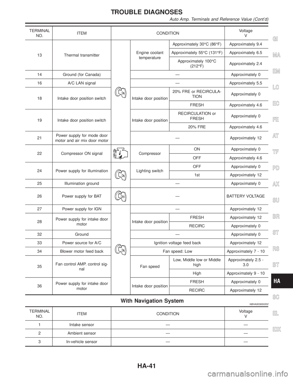
TERMINAL
NO.ITEM CONDITIONVoltage
V
13 Thermal transmitter
Engine coolant
temperatureApproximately 30ÉC (86ÉF) Approximately 9.4
Approximately 55ÉC (131ÉF) Approximately 6.5
Approximately 100ÉC
(212ÉF)Approximately 2.4
14 Ground (for Canada) Ð Approximately 0
16 A/C LAN signal Ð Approximately 5.5
18 Intake door position switch Intake door position20% FRE or RECIRCULA-
TIONApproximately 0
FRESH Approximately 4.6
19 Intake door position switch Intake door positionRECIRCULATION or
FRESHApproximately 0
20% FRE Approximately 4.6
21Power supply for mode door
motor and air mix door motorÐ Approximately 12
22 Compressor ON signal
CompressorON Approximately 0
OFF Approximately 4.6
24 Power supply for illumination
Lighting switchOFF Approximately 0
1st Approximately 12
25 Illumination ground Ð Approximately 0
26 Power supply for BAT
Ð BATTERY VOLTAGE
27 Power supply for IGN
Ð Approximately 12
28Power supply for intake door
motorIntake door positionFRESH Approximately 12
RECIRC Approximately 0
32 Ground Ð Approximately 0
33 Power source for A/C Ignition voltage feed back Approximately 12
34 Blower motor feed back Fan speed: Low Approximately7-10
35Fan control AMP. control sig-
nalFan speedLow, Middle low or Middle
highApproximately 2.5 -
3.0
High Approximately9-10
36Power supply for intake door
motorIntake door positionFRESH Approximately 0
RECIRC Approximately 12
With Navigation SystemNBHA0036S0202
TERMINAL
NO.ITEM CONDITIONVoltage
V
1 Intake sensor Ð Ð
2 Ambient sensor Ð Ð
3 In-vehicle sensor Ð Ð
GI
MA
EM
LC
EC
FE
AT
TF
PD
AX
SU
BR
ST
RS
BT
SC
EL
IDX
TROUBLE DIAGNOSES
Auto Amp. Terminals and Reference Value (Cont'd)
HA-41
Page 1842 of 2395
TERMINAL
NO.ITEM CONDITIONVoltage
V
25 Power supply for IGN
Ð Approximately 12
26Power supply for intake door
motorIntake door positionFRE,REC Approximately 12
REC,FRE Approximately 0
32 Ground Ð Approximately 0
33 Power source for A/C Ð Approximately 12
34 Blower motor feed back Fan speed: Low Approximately7-10
35Fan control amp. control sig-
nalFan speed: Low, Middle low or Middle highApproximately 2.5 -
3.0
Fan speed: High Approximately9-10
36Power supply for intake door
motorIntake door positionREC,FRE Approximately 12
FRE,REC Approximately 0GI
MA
EM
LC
EC
FE
AT
TF
PD
AX
SU
BR
ST
RS
BT
SC
EL
IDX
TROUBLE DIAGNOSES
Auto Amp. Terminals and Reference Value (Cont'd)
HA-43
Page 1844 of 2395
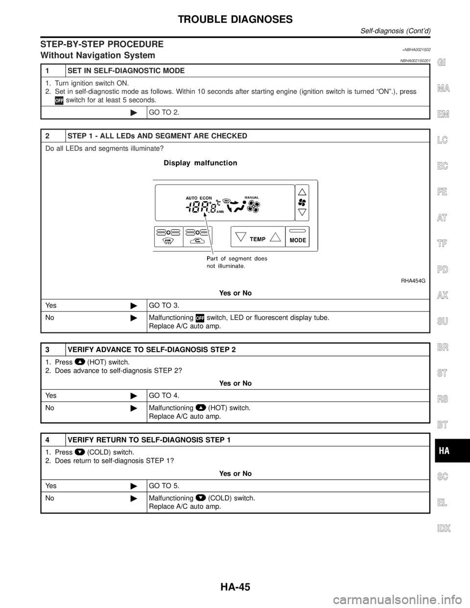
STEP-BY-STEP PROCEDURE=NBHA0021S02Without Navigation SystemNBHA0021S0201
1 SET IN SELF-DIAGNOSTIC MODE
1. Turn ignition switch ON.
2. Set in self-diagnostic mode as follows. Within 10 seconds after starting engine (ignition switch is turned ªONº.), press
switch for at least 5 seconds.
©GO TO 2.
2 STEP 1 - ALL LEDs AND SEGMENT ARE CHECKED
Do all LEDs and segments illuminate?
RHA454G
YesorNo
Ye s©GO TO 3.
No©Malfunctioning
switch, LED or fluorescent display tube.
Replace A/C auto amp.
3 VERIFY ADVANCE TO SELF-DIAGNOSIS STEP 2
1. Press(HOT) switch.
2. Does advance to self-diagnosis STEP 2?
YesorNo
Ye s©GO TO 4.
No©Malfunctioning
(HOT) switch.
Replace A/C auto amp.
4 VERIFY RETURN TO SELF-DIAGNOSIS STEP 1
1. Press(COLD) switch.
2. Does return to self-diagnosis STEP 1?
YesorNo
Ye s©GO TO 5.
No©Malfunctioning
(COLD) switch.
Replace A/C auto amp.
GI
MA
EM
LC
EC
FE
AT
TF
PD
AX
SU
BR
ST
RS
BT
SC
EL
IDX
TROUBLE DIAGNOSES
Self-diagnosis (Cont'd)
HA-45
Page 1846 of 2395
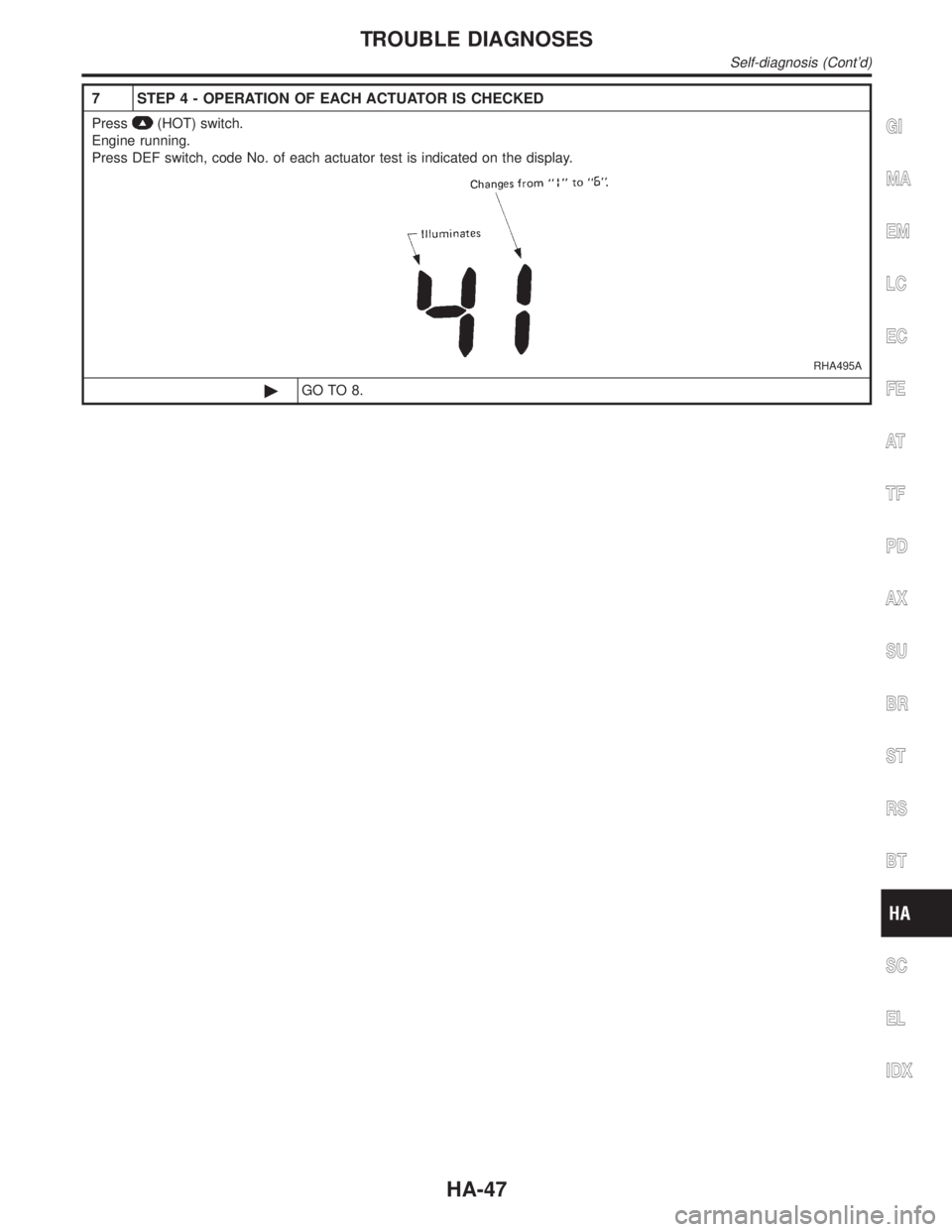
7 STEP 4 - OPERATION OF EACH ACTUATOR IS CHECKED
Press(HOT) switch.
Engine running.
Press DEF switch, code No. of each actuator test is indicated on the display.
RHA495A
©GO TO 8.
GI
MA
EM
LC
EC
FE
AT
TF
PD
AX
SU
BR
ST
RS
BT
SC
EL
IDX
TROUBLE DIAGNOSES
Self-diagnosis (Cont'd)
HA-47
Page 1848 of 2395
9 STEP 5 - TEMPERATURE OF EACH SENSOR IS CHECKED
Press(HOT) switch.
Code No.
appears on the display.
RHA492A
©GO TO 10.
10 CHECK AMBIENT SENSOR
Press(DEF) switch one time, temperature detected by ambient sensor is indicated on the display.
ECON shown in display indicates negative temperature reading.
NOTE:
If temperature shown on display greatly differs from actual temperature, check sensor circuit first, then inspect sensor.
RHA499G
OK or NG
OK©GO TO 11.
NG©Go to Ambient Sensor Circuit (HA-129).
GI
MA
EM
LC
EC
FE
AT
TF
PD
AX
SU
BR
ST
RS
BT
SC
EL
IDX
TROUBLE DIAGNOSES
Self-diagnosis (Cont'd)
HA-49
Page 1850 of 2395
13 CHECK MALFUNCTIONING SENSOR
Refer to the following chart for malfunctioning code No.
(If two or more sensors malfunction, corresponding code Nos. blink respectively two times.)
MTBL0083
*1: Conduct self-diagnosis STEP 2 under sunshine.
When conducting indoors, aim a light (more than 60W) at sunload sensor, otherwise Code No.
will indicate despite that
sunload sensor is functioning properly.
*2: HA-129
*3: HA-132
*4: HA-139
*5: HA-135
*6: HA-141
RHA455G
RHA501A
©INSPECTION END
GI
MA
EM
LC
EC
FE
AT
TF
PD
AX
SU
BR
ST
RS
BT
SC
EL
IDX
TROUBLE DIAGNOSES
Self-diagnosis (Cont'd)
HA-51


