Oil sensor INFINITI QX4 2001 Factory Service Manual
[x] Cancel search | Manufacturer: INFINITI, Model Year: 2001, Model line: QX4, Model: INFINITI QX4 2001Pages: 2395, PDF Size: 43.2 MB
Page 8 of 2395
19. A/T Does Not Shift: 22-> 11, When Selector
Lever²2²->²1²Position .........................................255
20. Vehicle Does Not Decelerate By Engine
Brake........................................................................256
21. TCM Self-diagnosis Does Not Activate (PNP,
Overdrive Control and Throttle Position Switches
Circuit Checks) ........................................................257
A/T SHIFT LOCK SYSTEM.........................................265
Description ...............................................................265
Wiring Diagram - SHIFT -........................................266
Diagnostic Procedure ..............................................267
KEY INTERLOCK CABLE..........................................271
Components.............................................................271
Removal ...................................................................271
Installation ................................................................272
ON-VEHICLE SERVICE..............................................273
Control Valve Assembly and Accumulators .............273
Revolution Sensor Replacement .............................274
Turbine Revolution Sensor Replacement................274
Rear Oil Seal Replacement .....................................274
Rear Oil Seal and Companion Flange Oil Seal
Replacement ............................................................275
Parking Components Inspection..............................275
Park/Neutral Position Switch Adjustment ................276
Manual Control Linkage Adjustment........................276
REMOVAL AND INSTALLATION...............................277
Removal ...................................................................277
Installation ................................................................278
OVERHAUL.................................................................281
Components.............................................................281
Oil Channel ..............................................................284
Locations of Needle Bearings, Thrust Washers
and Snap Rings .......................................................285
DISASSEMBLY............................................................286
REPAIR FOR COMPONENT PARTS.........................297Oil Pump ..................................................................297
Control Valve Assembly ...........................................301
Control Valve Upper Body .......................................307
Control Valve Lower Body .......................................312
Reverse Clutch ........................................................314
High Clutch ..............................................................317
Forward and Overrun Clutches ...............................320
Low & Reverse Brake..............................................324
Forward Clutch Drum Assembly ..............................328
Rear Internal Gear and Forward Clutch Hub ..........330
Band Servo Piston Assembly ..................................333
Parking Pawl Components ......................................337
ASSEMBLY..................................................................339
Assembly (1) ............................................................339
Adjustment ...............................................................347
Assembly (2) ............................................................349
SERVICE DATA AND SPECIFICATIONS (SDS).......356
General Specifications .............................................356
Shift Schedule..........................................................356
Stall Revolution ........................................................356
Line Pressure...........................................................356
Return Springs .........................................................357
Accumulator O-ring ..................................................358
Clutches and Brakes ...............................................358
Oil Pump and Low One-way Clutch ........................360
Total End Play..........................................................360
Reverse Clutch Drum End Play ..............................361
Removal and Installation .........................................361
Shift Solenoid Valves ...............................................361
Solenoid Valves .......................................................361
A/T Fluid Temperature Sensor.................................361
Turbine Revolution Sensor ......................................361
Revolution Sensor ...................................................362
Dropping Resistor ....................................................362GI
MA
EM
LC
EC
FE
TF
PD
AX
SU
BR
ST
RS
BT
HA
SC
EL
IDX
CONTENTS(Cont'd)
AT-3
Page 13 of 2395
IBefore assembly, apply a coat of recommended ATF to all
parts. Apply petroleum jelly to protect O-rings and seals, or
hold bearings and washers in place during assembly. Do not
use grease.
IExtreme care should be taken to avoid damage to O-rings,
seals and gaskets when assembling.
IReplace ATF cooler if excessive foreign material is found in oil
pan or clogging strainer. Refer to ªATF COOLER SERVICEº,
AT-9.
IAfter overhaul, refill the transmission with new ATF.
IWhen the A/T drain plug is removed, only some of the fluid is
drained. Old A/T fluid will remain in torque converter and ATF
cooling system.
Always follow the procedures when changing A/T fluid. Refer
to MA-21, ªChanging A/T Fluidº.
Service Notice or PrecautionsNBAT0004FAIL-SAFENBAT0004S01The TCM has an electronic Fail-Safe (limp home mode). This allows the vehicle to be driven even if a major
electrical input/output device circuit is damaged.
Under Fail-Safe, the vehicle always runs in third gear, even with a shift lever position of ª1º, ª2º or ªDº. The
customer may complain of sluggish or poor acceleration.
When the ignition key is turned ªONº following Fail-Safe operation, O/D OFF indicator lamp blinks for about
8 seconds. (For ªTCM SELF-DIAGNOSTIC PROCEDURE (No Tools)º, refer to AT-46.)
Fail-Safe may occur without electrical circuit damage if the vehicle is driven under extreme conditions (such
as excessive wheel spin followed by sudden braking). To recover normal shift pattern, turn the ignition key
ªOFFº for 5 seconds, then ªONº.
The blinking of the O/D OFF indicator lamp for about 8 seconds will appear only once and be cleared. The
customer may resume normal driving conditions.
Always follow the ªWORK FLOWº (Refer to AT-57).
The SELF-DIAGNOSIS results will be as follows:
The first SELF-DIAGNOSIS will indicate damage to the vehicle speed sensor or the revolution sensor.
During the next SELF-DIAGNOSIS, performed after checking the sensor, no damages will be indicated.
TORQUE CONVERTER SERVICENBAT0004S04The torque converter should be replaced under any of the following conditions:
IExternal leaks in the hub weld area.
IConverter hub is scored or damaged.
IConverter pilot is broken, damaged or fits poorly into crankshaft.
ISteel particles are found after flushing the cooler and cooler lines.
IPump is damaged or steel particles are found in the converter.
IVehicle has TCC shudder and/or no TCC apply. Replace only after all hydraulic and electrical diagnoses
have been made. (Converter clutch material may be glazed.)
IConverter is contaminated with engine coolant containing antifreeze.
IInternal failure of stator roller clutch.
IHeavy clutch debris due to overheating (blue converter).
ISteel particles or clutch lining material found in fluid filter or on magnet when no internal parts in unit are
worn or damaged Ð indicates that lining material came from converter.
The torque converter should not be replaced if:
IThe fluid has an odor, is discolored, and there is no evidence of metal or clutch facing particles.
PRECAUTIONS
Precautions (Cont'd)
AT-8
Page 34 of 2395
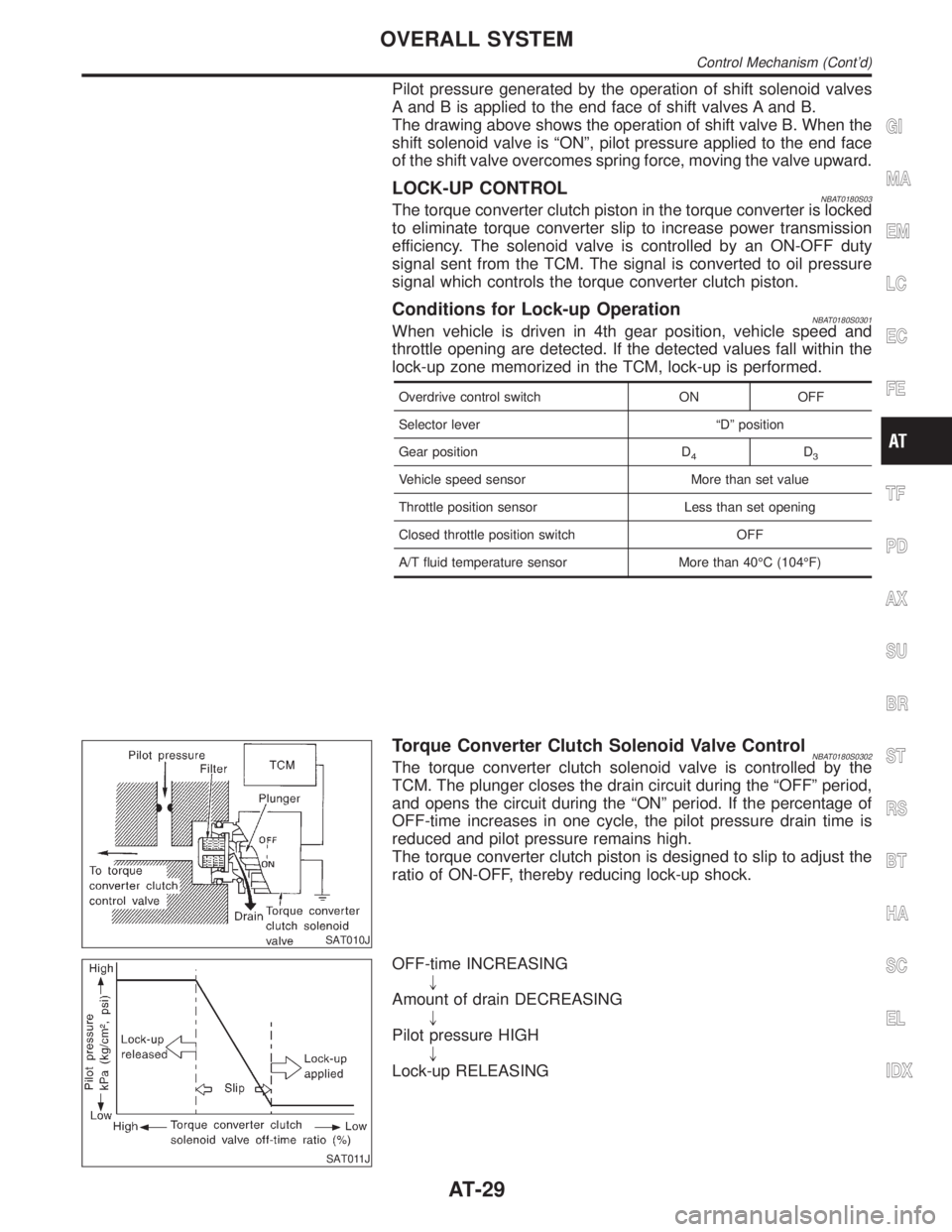
Pilot pressure generated by the operation of shift solenoid valves
A and B is applied to the end face of shift valves A and B.
The drawing above shows the operation of shift valve B. When the
shift solenoid valve is ªONº, pilot pressure applied to the end face
of the shift valve overcomes spring force, moving the valve upward.
LOCK-UP CONTROLNBAT0180S03The torque converter clutch piston in the torque converter is locked
to eliminate torque converter slip to increase power transmission
efficiency. The solenoid valve is controlled by an ON-OFF duty
signal sent from the TCM. The signal is converted to oil pressure
signal which controls the torque converter clutch piston.
Conditions for Lock-up OperationNBAT0180S0301When vehicle is driven in 4th gear position, vehicle speed and
throttle opening are detected. If the detected values fall within the
lock-up zone memorized in the TCM, lock-up is performed.
Overdrive control switch ON OFF
Selector lever ªDº position
Gear position D
4D3
Vehicle speed sensor More than set value
Throttle position sensor Less than set opening
Closed throttle position switch OFF
A/T fluid temperature sensor More than 40ÉC (104ÉF)
SAT010J
Torque Converter Clutch Solenoid Valve ControlNBAT0180S0302The torque converter clutch solenoid valve is controlled by the
TCM. The plunger closes the drain circuit during the ªOFFº period,
and opens the circuit during the ªONº period. If the percentage of
OFF-time increases in one cycle, the pilot pressure drain time is
reduced and pilot pressure remains high.
The torque converter clutch piston is designed to slip to adjust the
ratio of ON-OFF, thereby reducing lock-up shock.
SAT011J
OFF-time INCREASING
"
Amount of drain DECREASING
"
Pilot pressure HIGH
"
Lock-up RELEASING
GI
MA
EM
LC
EC
FE
TF
PD
AX
SU
BR
ST
RS
BT
HA
SC
EL
IDX
OVERALL SYSTEM
Control Mechanism (Cont'd)
AT-29
Page 68 of 2395
SAT493G
5. Start engine and measure line pressure at idle and stall speed.
IWhen measuring line pressure at stall speed, follow the
stall test procedure.
Line pressure:
Refer to SDS, AT-356.
JUDGEMENT OF LINE PRESSURE TESTNBAT0023S02
Judgement Suspected parts
At idleLine pressure is low in all posi-
tions.IOil pump wear
IControl piston damage
IPressure regulator valve or plug sticking
ISpring for pressure regulator valve damaged
IFluid pressure leakage between oil strainer and pressure regulator valve
IClogged strainer
Line pressure is low in particu-
lar position.IFluid pressure leakage between manual valve and particular clutch
IFor example, line pressure is:
Ð Low in ªRº and ª1º positions, but
Ð Normal in ªDº and ª2º positions.
Then, fluid leakage exists at or around low and reverse brake circuit.
Refer to ªCLUTCH AND BAND CHARTº, AT-17.
Line pressure is high.IMal-adjustment of throttle position sensor
IFluid temperature sensor damaged
ILine pressure solenoid valve sticking
IShort circuit of line pressure solenoid valve circuit
IPressure modifier valve sticking
IPressure regulator valve or plug sticking
IOpen in dropping resistor circuit
At stall speedLine pressure is low.IMal-adjustment of throttle position sensor
ILine pressure solenoid valve sticking
IShort circuit of line pressure solenoid valve circuit
IPressure regulator valve or plug sticking
IPressure modifier valve sticking
IPilot valve sticking
SAT786A
Road TestNBAT0024DESCRIPTIONNBAT0024S01IThe purpose of the test is to determine overall performance of
A/T and analyze causes of problems.
IThe road test consists of the following three parts:
1. Check before engine is started
2. Check at idle
3. Cruise test
GI
MA
EM
LC
EC
FE
TF
PD
AX
SU
BR
ST
RS
BT
HA
SC
EL
IDX
TROUBLE DIAGNOSIS Ð BASIC INSPECTION
Line Pressure Test (Cont'd)
AT-63
Page 91 of 2395

Items Symptom Condition Diagnostic Item Reference Page
Slips/Will Not
EngageVehicle will not
run in D, 1, 2
positions (but
runs in R posi-
tion). Clutch slips.
Very poor accel-
eration.
AT-230ON vehicle1. Fluid level AT-59
2. Line pressure test AT-62
3. Line pressure solenoid valve AT-162
4. Control valve assembly AT-273
5. Accumulator N-D AT-273
OFF vehicle6. Reverse clutch AT-314
7. High clutch AT-317
8. Forward clutch AT-320
9. Forward one-way clutch AT-330
10. Low one-way clutch AT-328
Clutches or
brakes slip some-
what in starting.ON vehicle1. Fluid level AT-59
2. Manual control linkage adjustment AT-276
3. Throttle position sensor (Adjustment) EC-174
4. Line pressure test AT-62
5. Line pressure solenoid valve AT-162
6. Control valve assembly AT-273
7. Accumulator N-D AT-273
OFF vehicle8. Forward clutch AT-320
9. Reverse clutch AT-314
10. Low & reverse brake AT-324
11. Oil pump AT-297
12. Torque converter AT-286
No creep at all.
AT-227, 230ON vehicle1. Fluid level AT-59
2. Line pressure test AT-62
3. Control valve assembly AT-273
OFF vehicle4. Forward clutch AT-320
5. Oil pump AT-297
6. Torque converter AT-286
Almost no shock
or clutches slip-
ping in change
from D
1to D2.ON vehicle1. Fluid level AT-59
2. Throttle position sensor (Adjustment) EC-174
3. Line pressure test AT-62
4. Accumulator servo release AT-273
5. Control valve assembly AT-273
OFF vehicle 6. Brake band AT-333
TROUBLE DIAGNOSIS Ð GENERAL DESCRIPTION
Symptom Chart (Cont'd)
AT-86
Page 93 of 2395

Items Symptom Condition Diagnostic Item Reference Page
Slips/Will Not
EngageRaces extremely
fast or slips in
changing from D
4or D3to D1when
depressing pedal.ON vehicle1. Fluid level AT-59
2. Throttle position sensor (Adjustment) EC-174
3. Line pressure test AT-62
4. Line pressure solenoid valve AT-162
5. Control valve assembly AT-273
OFF vehicle6. Forward clutch AT-320
7. Forward one-way clutch AT-330
8. Low one-way clutch AT-328
Vehicle will not
run in any posi-
tion.ON vehicle1. Fluid level AT-59
2. Manual control linkage adjustment AT-276
3. Line pressure test AT-62
4. Line pressure solenoid valve AT-162
OFF vehicle5. Oil pump AT-297
6. High clutch AT-317
7. Brake band AT-333
8. Low & reverse brake AT-324
9. Torque converter AT-286
10. Parking pawl components AT-337
NOT USEDEngine cannot be
started in P and N
positions.
AT-221ON vehicle1. Ignition switch and starter EL-9, and SC-10
2. Manual control linkage adjustment AT-276
3. Park/neutral position (PNP) switch
adjustmentAT-276
Engine starts in
positions other
than P and N.
AT-221ON vehicle1. Manual control linkage adjustment AT-276
2. Park/neutral position (PNP) switch
adjustmentAT-276
Transmission
noise in P and N
positions.ON vehicle1. Fluid level AT-59
2. Line pressure test AT-62
3. Throttle position sensor (Adjustment) EC-174
4. Vehicle speed sensor´A/T (Revolution
sensor) and vehicle speed sensor´MTRAT- 111 , 1 9 7
5. Engine speed signal AT-116
OFF vehicle6. Oil pump AT-297
7. Torque converter AT-286
Vehicle moves
when changing
into P position or
parking gear does
not disengage
when shifted out
of P position.
AT-222ON vehicle 1. Manual control linkage adjustment AT-276
OFF vehicle 2. Parking pawl components AT-337
TROUBLE DIAGNOSIS Ð GENERAL DESCRIPTION
Symptom Chart (Cont'd)
AT-88
Page 95 of 2395

Items Symptom Condition Diagnostic Item Reference Page
NOT USEDMaximum speed
not attained.
Acceleration poor.ON vehicle1. Fluid level AT-59
2. Park/neutral position (PNP) switch
adjustmentAT-276
3. Shift solenoid valve A AT-168
4. Shift solenoid valve B AT-172
5. Control valve assembly AT-273
OFF vehicle6. Reverse clutch AT-314
7. High clutch AT-317
8. Brake band AT-333
9. Low & reverse brake AT-324
10. Oil pump AT-297
11. Torque converter AT-286
Transmission
noise in D, 2, 1
and R positions.ON vehicle 1. Fluid level AT-59
ON vehicle 2. Torque converter AT-286
Engine brake
does not operate
in ª1º position.
AT-252ON vehicle1. Park/neutral position (PNP) switch
adjustmentAT-276
2. Manual control linkage adjustment AT-276
3. Throttle position sensor (Adjustment) EC-174
4. Vehicle speed sensor´A/T (Revolution
sensor) and vehicle speed sensor´MTRAT- 111 , 1 9 7
5. Shift solenoid valve A AT-168
6. Control valve assembly AT-273
7. Overrun clutch solenoid valve AT-185
OFF vehicle8. Overrun clutch AT-320
9. Low & reverse brake AT-324
Transmission
overheats.ON vehicle1. Fluid level AT-59
2. Engine idling rpm EC-431
3. Throttle position sensor (Adjustment) EC-174
4. Line pressure test AT-62
5. Line pressure solenoid valve AT-162
6. Control valve assembly AT-273
OFF vehicle7. Oil pump AT-297
8. Reverse clutch AT-314
9. High clutch AT-317
10. Brake band AT-333
11. Forward clutch AT-320
12. Overrun clutch AT-320
13. Low & reverse brake AT-324
14. Torque converter AT-286
TROUBLE DIAGNOSIS Ð GENERAL DESCRIPTION
Symptom Chart (Cont'd)
AT-90
Page 114 of 2395

4 CHECK A/T FLUID TEMPERATURE SENSOR WITH TERMINAL CORD ASSEMBLY
1. Turn ignition switch to ªOFFº position.
2. Disconnect terminal cord assembly connector on the right side of transfer assmebly.
3. Check resistance between terminals 8 and 9 when A/T is cold [20ÉC (68ÉF)].
SAT697I
Is resistance approx. 2.5 kW?
Ye s©GO TO 7.
No©GO TO 5.
5 DETECT MALFUNCTIONING ITEM
1. Remove oil pan.
2. Check the following items:
IA/T fluid temperature sensor
Refer to ªComponent Inspectionº, AT-110.
IHarness of terminal cord assembly for short or open
OK or NG
OK©GO TO 7.
NG©Repair or replace damaged parts.
6 CHECK INPUT SIGNAL OF A/T FLUID TEMPERATURE SENSOR (WITHOUT CONSULT-II)
Without CONSULT-II
1. Start engine.
2. Check voltage between TCM terminal 47 and ground while warming up A/T.
Voltage:
Cold [20ÉC (68ÉF)]®Hot [80ÉC (176ÉF)]:
Approximately 1.5V®0.5V
SAT518J
OK or NG
OK©GO TO 4.
NG©GO TO 3.
GI
MA
EM
LC
EC
FE
TF
PD
AX
SU
BR
ST
RS
BT
HA
SC
EL
IDX
DTC P0710 A/T FLUID TEMPERATURE SENSOR CIRCUIT
Diagnostic Procedure (Cont'd)
AT-109
Page 158 of 2395
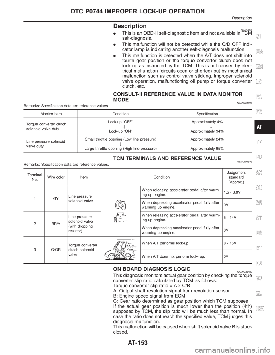
DescriptionNBAT0054IThis is an OBD-II self-diagnostic item and not available in TCM
self-diagnosis.
IThis malfunction will not be detected while the O/D OFF indi-
cator lamp is indicating another self-diagnosis malfunction.
IThis malfunction is detected when the A/T does not shift into
fourth gear position or the torque converter clutch does not
lock up as instructed by the TCM. This is not caused by elec-
trical malfunction (circuits open or shorted) but by mechanical
malfunction such as control valve sticking, improper solenoid
valve operation, malfunctioning oil pump or torque converter
clutch, etc.
CONSULT-II REFERENCE VALUE IN DATA MONITOR
MODE
NBAT0054S02Remarks: Specification data are reference values.
Monitor item Condition Specification
Torque converter clutch
solenoid valve dutyLock-up ªOFFº
"
Lock-up ªONºApproximately 4%
"
Approximately 94%
Line pressure solenoid
valve dutySmall throttle opening (Low line pressure)
"
Large throttle opening (High line pressure)Approximately 24%
"
Approximately 95%
TCM TERMINALS AND REFERENCE VALUENBAT0054S03Remarks: Specification data are reference values.
Terminal
No.Wire color Item ConditionJudgement
standard
(Approx.)
1GYLine pressure
solenoid valve
When releasing accelerator pedal after warm-
ing up engine.1.5 - 3.0V
When depressing accelerator pedal fully after
warming up engine.0V
2 BR/YLine pressure
solenoid valve
(with dropping
resistor)When releasing accelerator pedal after warm-
ing up engine.5 - 14V
When depressing accelerator pedal fully after
warming up engine.0V
3 G/ORTorque converter
clutch solenoid
valve
When A/T performs lock-up. 8 - 15V
When A/T does not perform lock- up. 0V
ON BOARD DIAGNOSIS LOGICNBAT0054S04This diagnosis monitors actual gear position by checking the torque
converter slip ratio calculated by TCM as follows:
Torque converter slip ratio = A x C/B
A: Output shaft revolution signal from revolution sensor
B: Engine speed signal from ECM
C: Gear ratio determined as gear position which TCM supposes
If the actual gear position is much lower than the position (4th)
supposed by TCM, the slip ratio will be much less than normal. In
case the ratio does not reach the specified value, TCM judges this
diagnosis malfunction.
This malfunction will be caused when shift solenoid valve B is stuck
closed.
GI
MA
EM
LC
EC
FE
TF
PD
AX
SU
BR
ST
RS
BT
HA
SC
EL
IDX
DTC P0744 IMPROPER LOCK-UP OPERATION
Description
AT-153
Page 199 of 2395

4 CHECK A/T FLUID TEMPERATURE SENSOR WITH TERMINAL CORD ASSEMBLY
1. Turn ignition switch to ªOFFº position.
2. Disconnect terminal cord assembly connector on the right side of transfer assmebly.
3. Check resistance between terminals 8 and 9 when A/T is cold [20ÉC (68ÉF)].
SAT697I
Is resistance approx. 2.5 kW?
Ye s©GO TO 7.
No©GO TO 5.
5 DETECT MALFUNCTIONING ITEM
1. Remove oil pan.
2. Check the following items:
IA/T fluid temperature sensor
Refer to ªComponent Inspectionº, AT-110.
IHarness of terminal cord assembly for short or open
OK or NG
OK©GO TO 7.
NG©Repair or replace damaged parts.
6 CHECK INPUT SIGNAL OF A/T FLUID TEMPERATURE SENSOR (WITHOUT CONSULT-II)
Without CONSULT-II
1. Start engine.
2. Check voltage between TCM terminal 47 and ground while warming up A/T.
Voltage:
Cold [20ÉC (68ÉF)]®Hot [80ÉC (176ÉF)]:
Approximately 1.5V®0.5V
SAT518J
OK or NG
OK©GO TO 4.
NG©GO TO 3.
DTC BATT/FLUID TEMP SEN (A/T FLUID TEMP SENSOR CIRCUIT AND TCM
POWER SOURCE)
Diagnostic Procedure (Cont'd)
AT-194