INFINITI QX4 2005 Factory Service Manual
QX4 2005
INFINITI
INFINITI
https://www.carmanualsonline.info/img/42/57035/w960_57035-0.png
INFINITI QX4 2005 Factory Service Manual
Trending: suspension, phone, trunk release, immobilizer, clock reset, battery location, fuel
Page 331 of 3419
AT-260
OVERHAUL
Revision: October 20052005 QX56
Locations of Adjusting Shims, Needle Bearings, Thrust Washers and Snap
Rings
ECS00CL4
2WD models
SCIA5196E
Page 332 of 3419
OVERHAUL
AT-261
D
E
F
G
H
I
J
K
L
MA
B
AT
Revision: October 20052005 QX56
4WD models
SCIA5197E
Page 333 of 3419
AT-262
DISASSEMBLY
Revision: October 20052005 QX56
DISASSEMBLYPFP:31020
DisassemblyECS00CL5
CAUTION:
Do not disassemble parts behind Drum Support. Refer to AT-1 6, "
Cross-Sectional View (2WD models)"
or AT-17, "Cross-Sectional View (4WD models)" .
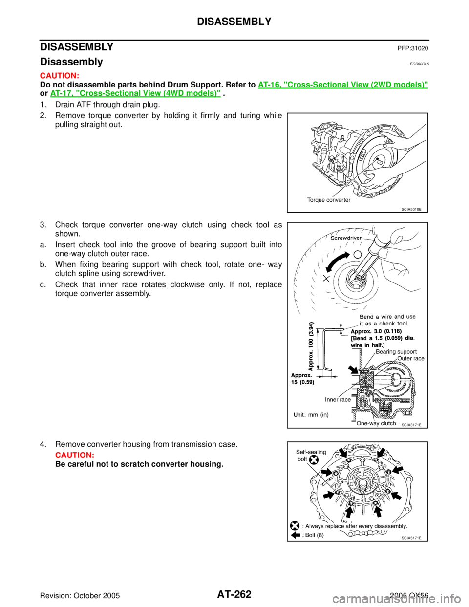
1. Drain ATF through drain plug.
2. Remove torque converter by holding it firmly and turing while
pulling straight out.
3. Check torque converter one-way clutch using check tool as
shown.
a. Insert check tool into the groove of bearing support built into
one-way clutch outer race.
b. When fixing bearing support with check tool, rotate one- way
clutch spline using screwdriver.
c. Check that inner race rotates clockwise only. If not, replace
torque converter assembly.
4. Remove converter housing from transmission case.
CAUTION:
Be careful not to scratch converter housing.
SCIA5010E
SCIA3171E
SCIA5171E
Page 334 of 3419
DISASSEMBLY
AT-263
D
E
F
G
H
I
J
K
L
MA
B
AT
Revision: October 20052005 QX56
5. Remove O-ring from input clutch assembly.
6. Remove tightening bolts for oil pump assembly and transmis-
sion case.
7. Attach sliding hammer to oil pump assembly and extract it
evenly from transmission case.
CAUTION:
�Fully tighten sliding hammer screw.
�Make sure that bearing race is installed to the oil pump
assembly edge surface.
8. Remove O-ring from oil pump assembly.
SCIA5 011 E
SCIA2300E
SCIA5474E
SCIA5172E
Page 335 of 3419
AT-264
DISASSEMBLY
Revision: October 20052005 QX56
9. Remove bearing race from oil pump assembly.
10. Remove needle bearing from front sun gear assembly.
11. Remove front sun gear assembly from front carrier assembly.
NOTE:
Remove front sun gear assembly by rotating left/right.
12. Remove seal rings from input clutch assembly.
13. Remove front carrier assembly, input clutch assembly and rear
internal gear as a unit.
CAUTION:
Be careful to remove it with needle bearing.
SCIA5252E
SCIA2808E
SCIA5014E
SCIA5269E
SCIA5173E
Page 336 of 3419
DISASSEMBLY
AT-265
D
E
F
G
H
I
J
K
L
MA
B
AT
Revision: October 20052005 QX56
14. Loosen lock nut and remove band servo anchor end pin from
transmission case.
15. Remove brake band from transmission case.
�To prevent brake linings from cracking or peeling, do not
stretch the flexible band unnecessarily. When removing
the brake band, always secure it with a clip as shown in
the figure at left.
Leave the clip in position after removing the brake band.
�Check brake band facing for damage, cracks, wear or
burns.
16. Remove mid carrier assembly and rear carrier assembly as a
unit.
SCIA5016E
SCIA5345E
SAT6 5 5
SCIA5344E
Page 337 of 3419
AT-266
DISASSEMBLY
Revision: October 20052005 QX56
17. Remove mid carrier assembly from rear carrier assembly.
18. Remove needle bearing (front side) from mid carrier assembly.
19. Remove needle bearing (rear side) from mid carrier assembly.
20. Remove bearing race from rear carrier assembly.
21. Remove needle bearing from rear carrier assembly.
SCIA5174E
SCIA5176E
SCIA5177E
SCIA5178E
SCIA5179E
Page 338 of 3419
DISASSEMBLY
AT-267
D
E
F
G
H
I
J
K
L
MA
B
AT
Revision: October 20052005 QX56
22. Remove mid sun gear assembly, rear sun gear assembly and
high and low reverse clutch hub as a unit.
CAUTION:
Be careful to remove then with bearing races and needle
bearing.
23. Remove high and low reverse clutch assembly from direct clutch
assembly.
CAUTION:
Make sure that needle bearing is installed to the high and
low reverse clutch assembly edge surface.
24. Remove direct clutch assembly from reverse brake.
25. Remove needle bearing from drum support edge surface.
26. Remove snap ring from A/T assembly harness connector.
SCIA5018E
SCIA2306E
SCIA5019E
SCIA5198E
SCIA5021E
Page 339 of 3419
AT-268
DISASSEMBLY
Revision: October 20052005 QX56
27. Push A/T assembly harness connector.
CAUTION:
Be careful not to damage connector.
28. Remove oil pan and oil pan gasket, refer to AT-229, "
Removal" .
29. Disconnect A/T fluid temperature sensor 2 connector.
CAUTION:
Be careful not to damage connector.
30. Straighten terminal clip to free terminal cord assembly and A/T
fluid temperature sensor 2 harness.
31. Disconnect revolution sensor connector.
CAUTION:
Be careful not to damage connector.
SCIA5022E
SCIA5023E
SCIA5446E
SCIA5024E
Page 340 of 3419
DISASSEMBLY
AT-269
D
E
F
G
H
I
J
K
L
MA
B
AT
Revision: October 20052005 QX56
32. Straighten terminal clips to free revolution sensor harness.
33. Remove bolts A, B and C from control valve with TCM.
34. Remove control valve with TCM from transmission case.
CAUTION:
When removing, be careful with transmission assembly ter-
minal connector and the manual valve notch and manual
plate height. Remove it vertically.
35. Remove A/T fluid temperature sensor 2 with bracket from con-
trol valve with TCM.
36. Remove bracket from A/T fluid temperature sensor 2.
SCIA5293E
Bolt symbol Length mm (in) Number of bolts
A 42 (1.65) 5
B 55 (2.17) 6
C 40 (1.57) 1
SCIA5025E
SCIA5308E
SCIA5301E
SCIA5264E
Trending: key, radio controls, ESP, manual transmission, fuse chart, low oil pressure, keyless entry


