Gps antenna INFINITI QX56 2007 Factory User Guide
[x] Cancel search | Manufacturer: INFINITI, Model Year: 2007, Model line: QX56, Model: INFINITI QX56 2007Pages: 3061, PDF Size: 64.56 MB
Page 676 of 3061

AV-136
< SERVICE INFORMATION >
NAVIGATION SYSTEM
YES or NO
YES >>AV-103, "Confirmation/Adjustment Mode".
NO >>AV-136, "
Driving Test".
Radio Wave from GPS Satellite Is Not ReceivedINFOID:0000000003533766
1.CHECK ENVIRONMENT
Check if any metal object that intercepts radio waves or an object that emits radio waves (such as a portable
phone) is located near the GPS antenna. Check if the vehicle is shielded by a building.
OK or NG
OK >> System is not malfunctioning. The GPS antenna may not be able to receive radio waves from the
GPS satellite if it is shielded by metal object or an object emitting radio waves is placed near it.
NG >> GO TO 2.
2.SELF-DIAGNOSIS
Perform “Self-diagnosis mode” of the self-diagnosis function. Refer to AV-101, "
Self-Diagnosis Mode (NAVI)".
OK or NG
OK >> Replace GPS antenna. Refer to AV-145, "Removal and Installation".
NG >> Check the malfunctioning parts.
Driving TestINFOID:0000000003533767
1.DRIVING TEST 1
1. Scroll the map screen to display the area to make correction. Press “ENTER” and select “CURRENT
LOCATION CORRECTION”.
2. Correct direction of the vehicle mark.
3. Perform the distance correction of the "CONFIRMATION/ADJUSTMENT" mode.
Note: Normally, adjustment is not necessary because this system has automatic distance correction func-
tion. However, when a tire chain is fitted, adjustment in accordance with the tire diameter ratio must be
made.
4. Are symptoms malfunctioning to the AV-137, "
Example of Symptom Judged Not Malfunction" after driving
the vehicle?
YES or NO
YES >> Limit of the location detection capacity of the navigation system.
NO >> GO TO 2.
2.DRIVING TEST 2
• Did any malfunction occur when the proper test in the following test patterns is performed?
• Test pattern
Driving test finds the difference between the symptoms monitored with and without each sensor.
- Test pattern 1: Test method with no GPS location correction
Disconnect GPS antenna connector connected to the NAVI control unit. Accurately adjust the current loca-
tion and the direction, then drive the vehicle.
- Test pattern 2: Test method with no map-matching
Accurately adjust the current location and the direction. Eject the map DVD-ROM from the NAVI control unit
with ignition switch turned to OFF, then drive the vehicle. After driving, insert the map DVD-ROM back in the
unit, display the track of the vehicle on the map screen and compare it with the actual road configuration.
• Sample tests
-
Perform test pattern 1.
-
Perform test pattern 1 & 2.
Compare the track of the vehicle on the map screen and the actual road configuration. For fairly accurate
tracking, plotting shall be made every several hundred meters (feet).
-
Perform test pattern 1 & 2.
Drive on a road of which distance is accurately known (by utilizing distance posts on a highway). Calculate
the rate of change (increased/decreased) of the distance by comparing with the actual distance.
Page 684 of 3061

AV-144
< SERVICE INFORMATION >
NAVIGATION SYSTEM
PLACE AND SOMETIMES IT IS WRONG PLACE
The conditions of the GPS antenna (GPS data) and gyroscope (angular speed sensor) change gradually.
Depending on the road traveled and the operation of the steering wheel, the location detection results will be
different. Therefore, even on a road on which the location has never been wrong, conditions may cause the
vehicle mark to deviate.
LOCATION CORRECTION BY MAP-MATCHING IS SLOW
• The map-matching function needs to refer to the data of the surrounding area. It is necessary to drive some
distance for the function to work.
• Because map-matching operates on this principle, when there are many roads running in similar directions
in the surrounding area, no matching determination may be made. The location may not be corrected until
some special feature is found.
ALTHOUGH GPS RECEIVING DISPLAY IS GREEN, VEHICLE MARK DOES NOT RETURN TO
CORRECT LOCATION
• The GPS accuracy has an error of approximately 10 m (30 ft). In some cases the current-location mark may
not be on the correct street, even when GPS location-correction is done.
• The navigation system compares the results of GPS location detection with the results from map-matching
location detection. The one which is determined to have higher accuracy is used.
• GPS location correction may not be performed when the vehicle is stopped.
NAME OF CURRENT PLACE IS NOT DISPLAYED
The current place name may not be displayed if there are no place names displayed on the map screen.
CONTENTS OF DISPLAY DIFFER FOR BIRDVIEW™ AND THE (FLAT) MAP SCREEN
Difference of the BIRDVIEW™ screen from the flat map screen are as follows.
• The current place name displays names which are primarily in the direction of vehicle travel.
• The amount of time before the vehicle travel or turn angle is updated on the screen is longer than for the
(flat) map display.
• The conditions for display of place names, roads, and other data are different for nearby areas and for more
distant areas.
• Some thinning of the character data is done to prevent the display becoming too complex. In some cases
and in some locations, the display contents may differ.
• The same place name, street name, etc. may be displayed multiple times.
Page 686 of 3061

AV-146
< SERVICE INFORMATION >
NAVIGATION SYSTEM
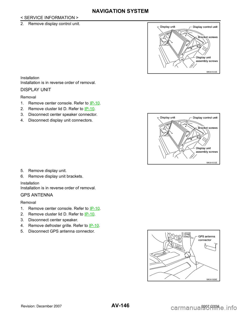
2. Remove display control unit.
Installation
Installation is in reverse order of removal.
DISPLAY UNIT
Removal
1. Remove center console. Refer to IP-10.
2. Remove cluster lid D. Refer to IP-10
.
3. Disconnect center speaker connector.
4. Disconnect display unit connectors.
5. Remove display unit.
6. Remove display unit brackets.
Installation
Installation is in reverse order of removal.
GPS ANTENNA
Removal
1. Remove center console. Refer to IP-10.
2. Remove cluster lid D. Refer to IP-10
.
3. Disconnect center speaker.
4. Remove defroster grille. Refer to IP-10
.
5. Disconnect GPS antenna connector.
WKIA1512E
WKIA1512E
WKIA1509E
Page 687 of 3061

NAVIGATION SYSTEM
AV-147
< SERVICE INFORMATION >
C
D
E
F
G
H
I
J
L
MA
B
AV
N
O
P
6. Remove GPS antenna.
Installation
Installation is in the reverse order of removal.
NAVI CONTROL UNIT
Removal
CAUTION:
To avoid damage, eject map DVD-ROM before removing the NAVI control unit.
1. Disconnect negative battery cable.
2. Remove front passenger seat. Refer to SE-83
.
3. Remove NAVI control unit kick shield screws (A).
4. Remove NAVI control unit kick shield (1).
5. Disconnect NAVI control unit connectors.
6. Remove NAVI control unit screws (B).
7. Remove NAVI control unit (2).
Installation
Installation is in the reverse order of removal.
STEERING WHEEL AUDIO CONTROL SWITCHES
Refer to AV-46, "Removal and Installation".
WKIA1508E
WKIA4354E
Page 2108 of 3061

IDX-4
ALPHABETICAL INDEX
Duct and grilles .............................................. ATC-170
DVD - Wiring Diagram ....................................... AV-75
DVD Entertainment System ............................... AV-72
DVD Player ........................................................ AV-73
E
ECM input/output signal ..................... EC-109
, EC-133
ECM power supply ............................. EC-150, EC-475
ECM relay ........................................................ EC-150
ECM/PW - Wiring diagram ............................... EC-476
ECTS - Wiring diagram .................................... EC-220
Electric sunroof .................................................. RF-10
Electric throttle control actuator ......... EC-595, EC-606
Electrical load signal circuit .............................. EC-657
Electrical units location ...................................... PG-65
Electronic ignition (EI) system ........................... EC-27
Engine control circuit diagram ......................... EC-107
Engine control component parts location ........... EC-98
Engine control module (ECM) .......................... EC-479
Engine control system diagram ......................... EC-24
Engine coolant .................................................. CO-10
Engine coolant temperature sensor (ECTS) ... EC-218,
EC-231
Engine fail-safe system ...................................... EC-93
Engine oil ............................................................. LU-8
Engine oil filter replacement ............................. MA-17
Engine oil precautions .......................................... GI-7
Engine oil replacement ..................................... MA-17
Engine removal ................................................. EM-74
Engine room cover ............................................ EM-12
Engine serial number .......................................... GI-50
ETC1 - Wiring diagram .................................... EC-596
ETC2 - Wiring diagram .................................... EC-591
ETC3 - Wiring diagram .................................... EC-602
EVAP canister .................................................... EC-36
EVAP canister purge volume control solenoid valve ....
EC-395
, EC-403
EVAP canister vent control valve ....... EC-410, EC-417
EVAP control system (small leak) diagnosis .. EC-387,
EC-441
, EC-449
EVAP control system pressure sensor .... EC-424, EC-
427, EC-433
EVAP control system purge flow monitoring diagnosis
EC-382
EVAP vapor lines inspection ............................. MA-20
Evaporative emission (EVAP) system ............... EC-33
Evaporator ..................................................... ATC-186
Exhaust manifold .............................................. EM-21
Exhaust system ................................................... EX-3
Exhaust system inspection .................................. EX-3
Expansion valve ............................................. ATC-188
F
F/FOG - Wiring diagram ..................................... LT-56
F/PUMP - Wiring diagram ................................ EC-666
Final drive pre-inspection ................................. FFD-15
Final drive removal and installation .. FFD-12, RFD-13
Flow charts .......................................................... GI-27
Fluid temperature sensor (A/T) ........................ AT-123
Fluids ................................................................ MA-11
Fluorescent leak detector .............................. ATC-189
Fog lamp, front ................................................... LT-54
Fog lamp, front, removal and installation ........... LT-62
Foot lamp ......................................................... LT-111
Freeze frame data ............................... EC-55, EC-121
Front brake solenoid valve ................. AT-139, AT-141
Front bumper ...................................................... EI-13
Front case (Transfer) .......................... TF-149, TF-176
Front combination lamp removal and installation LT-25
Front door ............................. BL-117, BL-121, GW-62
Front Door Trim ................................................... EI-32
Front drive shaft (Transfer) ................. TF-149, TF-176
Front fog lamp .................................................... LT-54
Front fog lamp removal and installation ............. LT-62
Front passenger air bag .................................. SRS-43
Front seat ........................................................... SE-89
Front seat belt ...................................................... SB-3
Front seat belt pre-tensioner ............... SRS-3, SRS-50
Front washer ...................................................... WW-4
Front wiper ......................................................... WW-4
FTS - Wiring diagram ....................................... AT-124
FTTS - Wiring diagram ...................... EC-334, EC-339
Fuel cut control (at no load high engine speed) EC-28
Fuel filter replacement ......................................... FL-5
Fuel gauge ............................................................ DI-5
Fuel injection system (Bank 1) .......... EC-311, EC-322
Fuel injection system (Bank 2) .......... EC-311, EC-322
Fuel injector .................................................... EC-659
Fuel injector and fuel tube ................................. EM-31
Fuel level sensor ................. EC-458, EC-460, EC-462
Fuel line inspection .............................................. FL-4
Fuel precautions ................................................... GI-5
Fuel pressure check .......................................... EC-82
Fuel pressure release ....................................... EC-82
Fuel pump ....................................................... EC-665
Fuel pump and gauge .......................................... FL-5
Fuel system .......................................................... FL-4
Fuel tank ............................................................ FL-10
Fuel tank temperature sensor ........... EC-332, EC-338
Fuel tank vacuum relief valve ........................... EC-36
FUELB1 - Wiring diagram ................. EC-313, EC-324
FUELB2 - Wiring diagram ................. EC-315, EC-326
Fuse ...................................................... PG-17, PG-77
Fuse and fusible link box .................................. PG-77
Fuse block ......................................................... PG-76
Fusible link ............................................ PG-17, PG-77
G
Garage jack and safety stand ............................. GI-42
Gauges ................................................................. DI-5
Generator .......................................................... SC-17
Generic scan tool (GST) ................................. EC-131
Glass ...................................... GW-11, GW-62, GW-65
Glove box lamp ................................................ LT-131
GPS antenna ..................................................... AV-82
Page 2123 of 3061

INSTRUMENT PANEL ASSEMBLY
IP-11
< SERVICE INFORMATION >
C
D
E
F
G
H
J
K
L
MA
B
IP
N
O
P Removal
1. Remove center console. Refer to IP-14, "Disassembly and Assembly".
2. Remove instrument lower cover LH. Refer to IP-10
.
3. Remove steering column. Refer to PS-10
.
4. Remove glove box assembly. Refer to IP-10
.
5. Remove front power socket LH. Refer to WW-41, "
Front Power Socket LH, Rear Cargo Power Socket".
6. Remove front power socket RH. Refer to WW-42, "
Front Power Socket RH (For Cigarette Lighter), Con-
sole Power Socket".
7. Remove combination meter. Refer to IP-10
.
8. Remove audio unit. Refer to AV-46, "
Removal and Installation".
9. Remove display unit. Refer to AV-145, "
Removal and Installation".
10. Remove lower knee protector LH.
11. Remove GPS antenna. Refer to AV-145, "
Removal and Installation".
12. Remove optical sensor. Refer to LT-44, "
Optical Sensor".
13. Remove side ventilator assembly LH.
14. Remove side ventilator assembly RH.
15. Remove front pillar finisher. Refer to EI-37
.
16. Remove passenger air bag module. Refer to SRS-39
.
17. Remove instrument panel.
18. Disconnect remaining instrument panel assembly electrical connectors.
Installation
Installation is in the reverse order of removal.
7. Instrument panel 8. Bin mat 9. Side ventilator assembly LH
10. Instrument lower cover LH 11. Lower knee protector LH 12. Steering column cover upper
13. Steering column cover lower 14. Center console lower cover LH 15. Combination meter
16. Audio unit bracket LH 17. Driver instrument stay 18. Audio unit
19. Passenger instrument stay 20. Display assembly 21. Switch assembly
22. Cluster lid A 23. Cluster lid D ventilator LH 24. Front passenger air bag status light
25. Power socket LH and power socket RH 26. Clock 27. Cluster lid C
28. Front air control 29. Audio control 30. Hazard switch
31. Cluster lid D ventilator RH 32. Cluster lid D 33. Glove box door
34. Glove box assembly 35. Lower instrument panel RH 36. Glove box striker
37. Rubber bumpers 38. Glove box damper 39. Audio unit bracket RH
40. Center console lower cover RH 41. Fuse block cover 42. Side ventilator assembly RH
43. Instrument panel bracket 44. Instrument panel speaker RH 45. Bracket assembly RH
46. Key cylinder escutcheon 47. Instrument lower cover RH