battery INFINITI QX56 2007 Factory Workshop Manual
[x] Cancel search | Manufacturer: INFINITI, Model Year: 2007, Model line: QX56, Model: INFINITI QX56 2007Pages: 3061, PDF Size: 64.56 MB
Page 453 of 3061
TROUBLE DIAGNOSISATC-83
< SERVICE INFORMATION >
C
DE
F
G H
I
K L
M A
B
AT C
N
O P
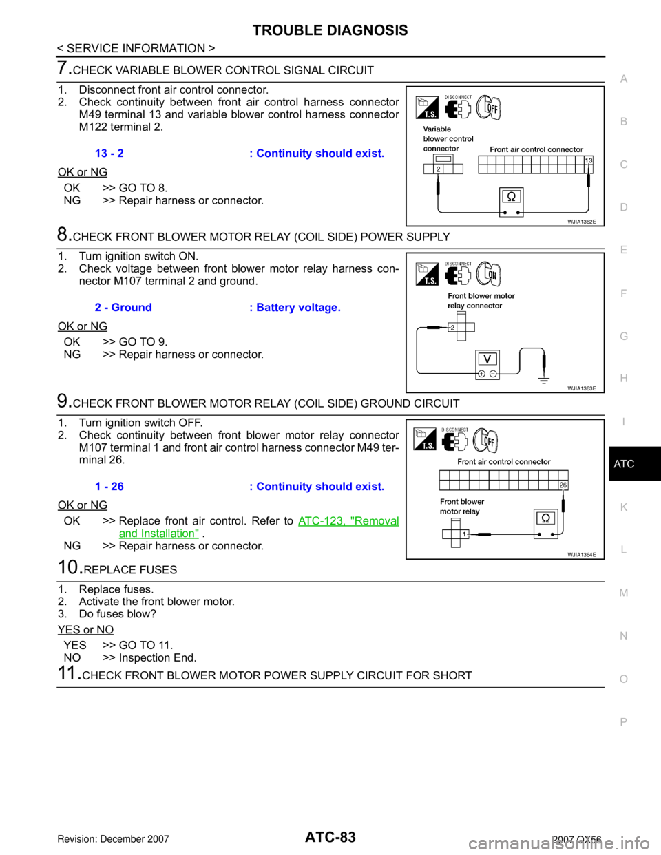
7.CHECK VARIABLE BLOWER CONTROL SIGNAL CIRCUIT
1. Disconnect front air control connector.
2. Check continuity between front air control harness connector
M49 terminal 13 and variable blower control harness connector
M122 terminal 2.
OK or NG
OK >> GO TO 8.
NG >> Repair harness or connector.
8.CHECK FRONT BLOWER MOTOR RELAY (COIL SIDE) POWER SUPPLY
1. Turn ignition switch ON.
2. Check voltage between front blower motor relay harness con- nector M107 terminal 2 and ground.
OK or NG
OK >> GO TO 9.
NG >> Repair harness or connector.
9.CHECK FRONT BLOWER MOTOR RELAY (COIL SIDE) GROUND CIRCUIT
1. Turn ignition switch OFF.
2. Check continuity between front blower motor relay connector M107 terminal 1 and front air control harness connector M49 ter-
minal 26.
OK or NG
OK >> Replace front air control. Refer to ATC-123, "Removal
and Installation" .
NG >> Repair harness or connector.
10.REPLACE FUSES
1. Replace fuses.
2. Activate the front blower motor.
3. Do fuses blow?
YES or NO
YES >> GO TO 11.
NO >> Inspection End.
11 .CHECK FRONT BLOWER MOTOR POWER SUPPLY CIRCUIT FOR SHORT 13 - 2 : Continuity should exist.
WJIA1362E
2 - Ground : Battery voltage.
WJIA1363E
1 - 26 : Continuity should exist.
WJIA1364E
Page 458 of 3061
ATC-88
< SERVICE INFORMATION >
TROUBLE DIAGNOSIS
Perform a complete operational check for any symptoms. Refer to ATC-50, "Operational Check (Front)".
Does another symptom exist?
YES >> Refer to ATC-32, "How to Perform Trouble Diagnosis for Quick and Accurate Repair" .
NO >> System OK.
3.CHECK FOR SERVICE BULLETINS
Check for any service bulletins.
>> GO TO 4.
4.CHECK REAR BLOWER MOTOR CIRCUIT
Check and verify rear blower motor operates in all speeds.
Does blower motor operate in all speeds?
YES >> GO TO 5.
NO >> Refer to "Trouble Diagnosis Procedure For Rear Blower Motor (1 - 4 Speed)".
5.PERFORM SELF-DIAGNOSIS
Perform self-diagnosis to check for any codes. Refer to ATC-48, "
A/C System Self-Diagnosis Function" .
Are any self-diagnosis codes present?
YES >> Refer to ATC-48, "A/C System Self-Diagnosis Function".
NO >> GO TO 6.
6.RECHECK FOR ANY SYMPTOMS
Perform a complete operational check for any symptoms. Refer to ATC-50, "
Operational Check (Front)" .
Does another symptom exist?
YES >> Refer to ATC-32, "How to Perform Trouble Diagnosis for Quick and Accurate Repair".
NO >> Replace front air control. Refer to ATC-123, "
Removal and Installation".
1.DIAGNOSTIC PROCEDURE
Blower motor rotates normally at each speed.
OK or NG
OK >> Inspection End.
NG >> 1. Does not rotate at any speed, GO TO 2. 2. Does not rotate at 1 - 3 speed, GO TO 13.
3. Does not rotate at 4 speed, GO TO 18.
2.CHECK FUSES
Check 15A fuses [Nos. 10 and 11, located in the fuse block (J/B)]. Refer to PG-73
.
OK or NG
OK >> GO TO 3.
NG >> GO TO 8.
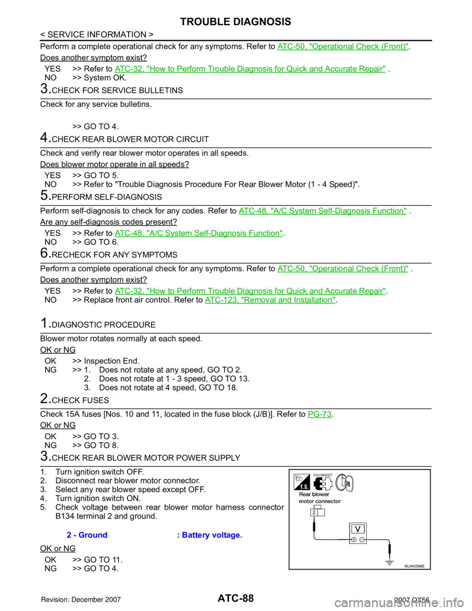
3.CHECK REAR BLOWER MOTOR POWER SUPPLY
1. Turn ignition switch OFF.
2. Disconnect rear blower motor connector.
3. Select any rear blower speed except OFF.
4. Turn ignition switch ON.
5. Check voltage between rear blower motor harness connector B134 terminal 2 and ground.
OK or NG
OK >> GO TO 11.
NG >> GO TO 4. 2 - Ground : Battery voltage.WJIA0596E
Page 459 of 3061
TROUBLE DIAGNOSISATC-89
< SERVICE INFORMATION >
C
DE
F
G H
I
K L
M A
B
AT C
N
O P
4.CHECK REAR BLOWER MOTOR RELAY
Turn ignition switch OFF.
Refer to "Rear Blower Motor Relay".
OK or NG
OK >> GO TO 5.
NG >> Replace rear blower motor relay.
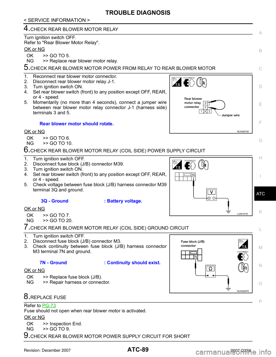
5.CHECK REAR BLOWER MOTOR POWER FR OM RELAY TO REAR BLOWER MOTOR
1. Reconnect rear blower motor connector.
2. Disconnect rear blower motor relay J-1.
3. Turn ignition switch ON.
4. Set rear blower switch (front) to any position except OFF, REAR, or 4 - speed.
5. Momentarily (no more than 4 seconds), connect a jumper wire
between rear blower motor relay connector J-1 (harness side)
terminals 3 and 5.
OK or NG
OK >> GO TO 6.
NG >> GO TO 10.
6.CHECK REAR BLOWER MOTOR RELAY (COIL SIDE) POWER SUPPLY CIRCUIT
1. Turn ignition switch OFF.
2. Disconnect fuse block (J/B) connector M39.
3. Turn ignition switch ON.
4. Set rear blower switch (front) to any position except OFF, REAR, or 4 - speed.
5. Check voltage between fuse block (J/B) harness connector M39 terminal 3Q and ground.
OK or NG
OK >> GO TO 7.
NG >> GO TO 20.
7.CHECK REAR BLOWER MOTOR RE LAY (COIL SIDE) GROUND CIRCUIT
1. Turn ignition switch OFF.
2. Disconnect fuse block (J/B) connector M3.
3. Check continuity between fuse block (J/B) harness connector M3 terminal 7N and ground.
OK or NG
OK >> Replace fuse block (J/B).
NG >> Repair harness or connector.
8.REPLACE FUSE
Refer to PG-73
Fuse should not open when rear blower motor is activated.
OK or NG
OK >> Inspection End.
NG >> GO TO 9.
9.CHECK REAR BLOWER MOTOR POWER SUPPLY CIRCUIT FOR SHORTRear blower motor should rotate.
WJIA0972E
3Q - Ground : Battery voltage.
LJIA0101E
7N - Ground : Continuity should exist.
WJIA0597E
Page 468 of 3061

ATC-98
< SERVICE INFORMATION >
TROUBLE DIAGNOSIS
YES or NO
YES >> • WITH CONSULT-IIGO TO 5.
• WITHOUT CONSULT-II GO TO 6.
NO >> Check 10A fuse (No. 42, located in IPDM E/R), and GO TO 3.
3.CHECK CIRCUIT CONTINUITY BETW EEN IPDM E/R AND COMPRESSOR
1. Turn ignition switch OFF.
2. Disconnect IPDM E/R connector and compressor (magnet clutch) connector.
3. Check continuity between IPDM E/R harness connector E119 terminal 11 and compressor harness connector F3 terminal 1.
OK or NG
OK >> GO TO 4.
NG >> Repair harness or connector.
4.CHECK MAGNET CLUTCH CIRCUIT
Check for operation sound when applying battery voltage direct cur-
rent to terminal.
OK or NG
OK >> Replace IPDM E/R. Refer to PG-28, "Removal and
Installation of IPDM E/R".
NG >> Replace magnet clutch. Refer to ATC-155, "
Removal
and Installation for Compressor Clutch".
5.CHECK BCM INPUT (COMPRESSOR ON) SIGNAL
Check compressor ON/OFF signal. Refer to ATC-30, "
CONSULT-II
Function (HVAC)" .
OK or NG
OK >> GO TO 8.
NG >> GO TO 6.
6.CHECK CIRCUIT CONTINUITY BETWEE N BCM AND FRONT AIR CONTROL
1. Turn ignition switch OFF.
2. Disconnect BCM connector and front air control connector.
3. Check continuity between BCM harness connector M18 terminal 27 and front air control harness connector M49 terminal 12.
OK or NG
OK >> GO TO 7.
NG >> Repair harness or connector.
11 – 1 : Continuity should exist.
WJIA0560E
SJIA0197E
A/C SW ON : COMP ON SIG ON
A/C SW OFF : COMP ON SIG OFF
WJIA0469E
27 - 12 Continuity should exist.
WJIA1443E
Page 483 of 3061
TROUBLE DIAGNOSISATC-113
< SERVICE INFORMATION >
C
DE
F
G H
I
K L
M A
B
AT C
N
O P
Does another symptom exist?
YES >> Refer to ATC-32, "How to Perform Trouble Diagnosis for Quick and Accurate Repair".
NO >> Replace front air control. Refer to ATC-123, "
Removal and Installation".
Water Valve CircuitINFOID:0000000003533265
COMPONENT DESCRIPTION
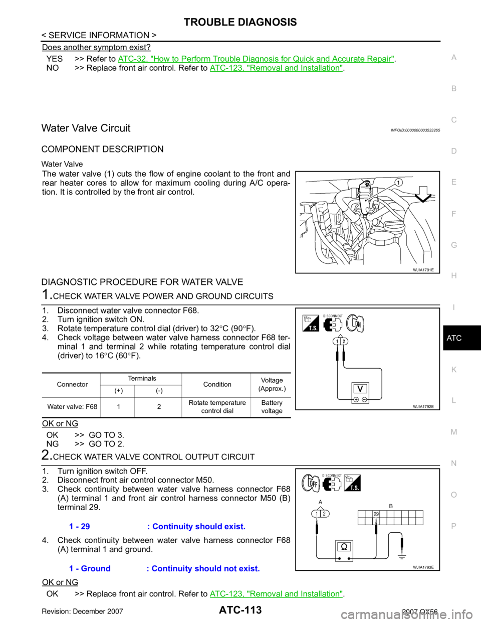
Water Valve
The water valve (1) cuts the flow of engine coolant to the front and
rear heater cores to allow for maximum cooling during A/C opera-
tion. It is controlled by the front air control.
DIAGNOSTIC PROCEDURE FOR WATER VALVE
1.CHECK WATER VALVE POWER AND GROUND CIRCUITS
1. Disconnect water valve connector F68.
2. Turn ignition switch ON.
3. Rotate temperature control dial (driver) to 32 °C (90 °F).
4. Check voltage between water valve harness connector F68 ter- minal 1 and terminal 2 while rotating temperature control dial
(driver) to 16 °C (60 °F).
OK or NG
OK >> GO TO 3.
NG >> GO TO 2.
2.CHECK WATER VALVE CONTROL OUTPUT CIRCUIT
1. Turn ignition switch OFF.
2. Disconnect front air control connector M50.
3. Check continuity between water valve harness connector F68 (A) terminal 1 and front air control harness connector M50 (B)
terminal 29.
4. Check continuity between water valve harness connector F68 (A) terminal 1 and ground.
OK or NG
OK >> Replace front air control. Refer to ATC-123, "Removal and Installation".
WJIA1791E
ConnectorTe r m i n a l s
Condition Voltage
(Approx.)
(+) (-)
Water valve: F68 1 2 Rotate temperature
control dial Battery
voltage
WJIA1792E
1 - 29 : Continuity should exist.
1 - Ground : Continuity should not exist.
WJIA1793E
Page 484 of 3061
ATC-114
< SERVICE INFORMATION >
TROUBLE DIAGNOSIS
NG >> Repair harness or connector.
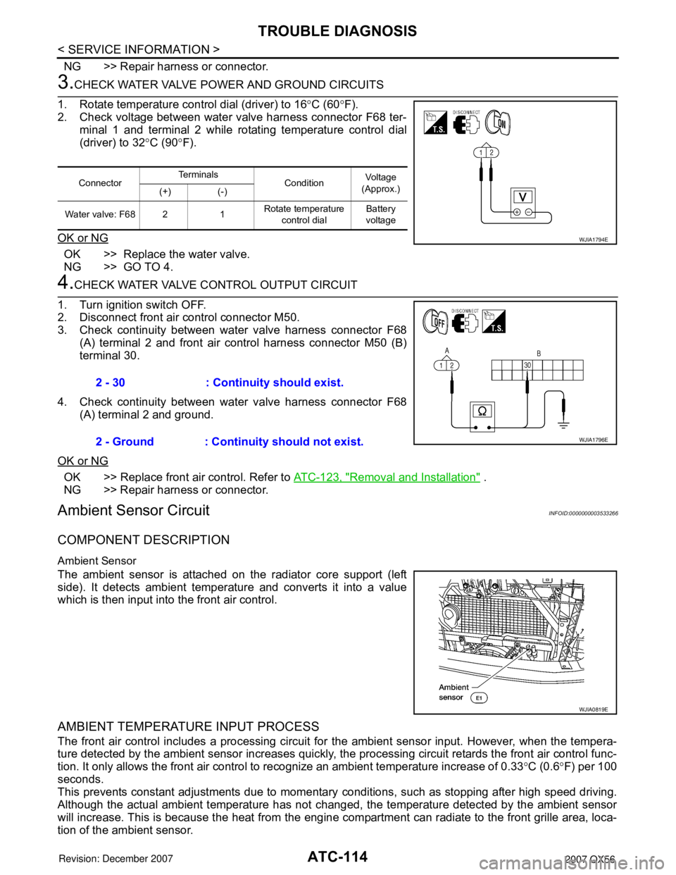
3.CHECK WATER VALVE POWER AND GROUND CIRCUITS
1. Rotate temperature control dial (driver) to 16 °C (60 °F).
2. Check voltage between water valve harness connector F68 ter- minal 1 and terminal 2 while rotating temperature control dial
(driver) to 32 °C (90 °F).
OK or NG
OK >> Replace the water valve.
NG >> GO TO 4.
4.CHECK WATER VALVE CONTROL OUTPUT CIRCUIT
1. Turn ignition switch OFF.
2. Disconnect front air control connector M50.
3. Check continuity between water valve harness connector F68 (A) terminal 2 and front air control harness connector M50 (B)
terminal 30.
4. Check continuity between water valve harness connector F68 (A) terminal 2 and ground.
OK or NG
OK >> Replace front air control. Refer to ATC-123, "Removal and Installation" .
NG >> Repair harness or connector.
Ambient Sensor CircuitINFOID:0000000003533266
COMPONENT DESCRIPTION
Ambient Sensor
The ambient sensor is attached on the radiator core support (left
side). It detects ambient temperature and converts it into a value
which is then input into the front air control.
AMBIENT TEMPERATURE INPUT PROCESS
The front air control includes a processing circuit for the ambient sensor input. However, when the tempera-
ture detected by the ambient sensor increases quickly, t he processing circuit retards the front air control func-
tion. It only allows the front air control to recognize an ambient temperature increase of 0.33 °C (0.6 °F) per 100
seconds.
This prevents constant adjustments due to momentary conditions, such as stopping after high speed driving.
Although the actual ambient temperature has not changed, the temperature detected by the ambient sensor
will increase. This is because the heat from the engine co mpartment can radiate to the front grille area, loca-
tion of the ambient sensor.
Connector Te r m i n a l s
Condition Voltage
(Approx.)
(+) (-)
Water valve: F68 2 1 Rotate temperature
control dial Battery
voltage
WJIA1794E
2 - 30 : Continuity should exist.
2 - Ground : Continuity should not exist.
WJIA1796E
WJIA0819E
Page 503 of 3061
HEATER & COOLING UNIT ASSEMBLYATC-133
< SERVICE INFORMATION >
C
DE
F
G H
I
K L
M A
B
AT C
N
O P
Rear Heater and Cooling Unit Assembly
Removal and InstallationINFOID:0000000003533279
FRONT HEATER AND COOLING UNIT ASSEMBLY
Removal
1. Move the two front seats to the rearmost position on the seat track.
2. Disconnect the battery negative terminal and battery positive terminal.
3. Discharge the refrigerant from the A/C system. Refer to ATC-150, "
HFC-134a (R-134a) Service Proce-
dure".
4. Drain the coolant from the engine cooling system. Refer to MA-12, "
Changing Engine Coolant".
WJIA2315E
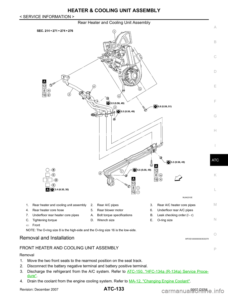
1. Rear heater and cooling unit assembly 2. Rear A/C pipes 3. Rear A/C heater core pipes
4. Rear heater core hose 5. Rear blower motor 6. Underfloor rear A/C pipes
7. Underfloor rear heater core pipes A. Bolt torque specifications B. Leak checking order (l - r)
C. Tightening torque D. Wrench size E. O-ring size
⇐Front
NOTE: The O-ring size 8 is the high-side and the O-ring size 16 is the low-side.
Page 528 of 3061
ATC-158
< SERVICE INFORMATION >
REFRIGERANT LINES
BREAK-IN OPERATION
When replacing compressor clutch assembly, always conduct the break-in operation. This is done by engag-
ing and disengaging the clutch about 30 times. Break-in operation raises the level of transmitted torque.
Removal and Installation for Low-Pressure Flexible HoseINFOID:0000000003533295
REMOVAL
1. Remove the engine room cover using power tools.
2. Remove the engine air cleaner and air ducts. Refer to EM-15
.
3. Remove the cowl top extension. Refer to EI-17
.
4. Discharge the refrigerant. Refer to ATC-150, "
HFC-134a (R-134a) Service Procedure".
CAUTION:
Cap or wrap the joint of the pipe with suitable mate rial such as vinyl tape to avoid the entry of air.
5. Remove the low-pressure flexible hose.
INSTALLATION
Installation is in the reverse order of removal.
Refer to ATC-152, "
Component".
CAUTION:
• Replace the O-ring of the low-pr essure flexible hose with a new one, then apply compressor oil to it
when installing it.
• After charging refrigerant, check for leaks.
Removal and Installation for High-pressure Flexible HoseINFOID:0000000003533296
REMOVAL
1. Remove the engine under cover.
2. Remove the engine air cleaner and air ducts. Refer to EM-15
.
3. Discharge the refrigerant. Refer to ATC-150, "
HFC-134a (R-134a) Service Procedure".
4. Remove the high-pressure flexible hose. CAUTION:
Cap or wrap the joint of the pipe with suitable mate rial such as vinyl tape to avoid the entry of air.
INSTALLATION
Installation is in the reverse order of removal.
Refer to ATC-152, "
Component".
CAUTION:
• Replace the O-ring of the high-pressure flexible hose with a new one, then apply compressor oil to it
when installing it.
• After charging refrigerant, check for leaks.
Removal and Installation for High-pressure PipeINFOID:0000000003533297
REMOVAL
1. Remove the cowl top extension. Refer to EI-17.
2. Disconnect the battery negative terminal and positive battery terminal.
3. Reposition the IPDM E/R aside.
4. Remove the front right wheel and tire assembly. Refer to WT-7, "
Rotation".
5. Position aside the front floor insulator.
6. Discharge the refrigerant. Refer to ATC-150, "
HFC-134a (R-134a) Service Procedure".
7. Remove the low-pressure pipe. Refer to ATC-159, "
Removal and Installation for Low-Pressure Pipe".
8. Remove the high-pressure pipe. CAUTION:
Cap or wrap the joint of the pipe with suitable mate rial such as vinyl tape to avoid the entry of air.
INSTALLATION
Installation is in the reverse order of removal.
Page 530 of 3061
ATC-160
< SERVICE INFORMATION >
REFRIGERANT LINES
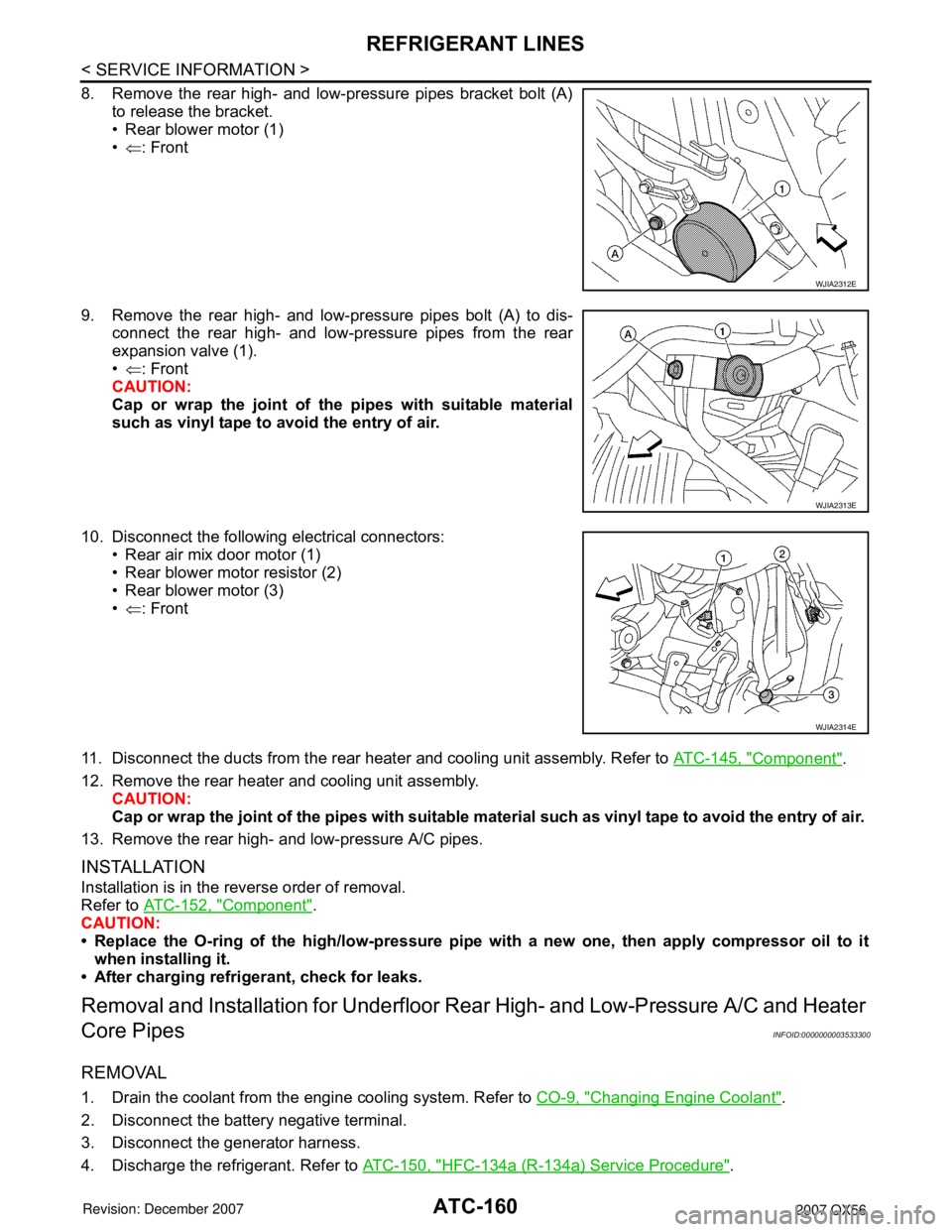
8. Remove the rear high- and low-pressure pipes bracket bolt (A)to release the bracket.
• Rear blower motor (1)
•⇐ : Front
9. Remove the rear high- and low-pressure pipes bolt (A) to dis- connect the rear high- and low-pressure pipes from the rear
expansion valve (1).
•⇐ : Front
CAUTION:
Cap or wrap the joint of the pipes with suitable material
such as vinyl tape to avoid the entry of air.
10. Disconnect the following electrical connectors: • Rear air mix door motor (1)
• Rear blower motor resistor (2)
• Rear blower motor (3)
•⇐ : Front
11. Disconnect the ducts from the rear heater and cooling unit assembly. Refer to ATC-145, "
Component".
12. Remove the rear heater and cooling unit assembly. CAUTION:
Cap or wrap the joint of the pipes with suitable material such as viny l tape to avoid the entry of air.
13. Remove the rear high- and low-pressure A/C pipes.
INSTALLATION
Installation is in the reverse order of removal.
Refer to ATC-152, "
Component".
CAUTION:
• Replace the O-ring of th e high/low-pressure pipe with a new one, then apply compressor oil to it
when installing it.
• After charging refrigerant, check for leaks.
Removal and Installati on for Underfloor Rear High- and Low-Pressure A/C and Heater
Core Pipes
INFOID:0000000003533300
REMOVAL
1. Drain the coolant from the engine cooling system. Refer to CO-9, "Changing Engine Coolant".
2. Disconnect the battery negative terminal.
3. Disconnect the generator harness.
4. Discharge the refrigerant. Refer to ATC-150, "
HFC-134a (R-134a) Service Procedure".
WJIA2312E
WJIA2313E
WJIA2314E
Page 560 of 3061

AV-20
< SERVICE INFORMATION >
AUDIO
Terminal and Reference Value for Audio Unit
INFOID:0000000003533667
Te r m i n a l
(Wire color)
ItemSignal
input/
outputCondition
Reference value
(Approx.)Example of symptom
+–Ignition
switchOperation
2 (W) 1 (B)Audio sound
signal front
LHOutput ONReceive audio
signalNo sound from front
door speaker LH or
tweeter LH.
4 (Y) 3 (BR)Audio sound
signal front
RHOutput ONReceive audio
signalNo sound from front
door speaker RH or
tweeter RH.
5 (G/W) GroundAntenna
signalOutput ON – More than 10V Poor radio reception.
6 (Y) GroundBattery pow-
erInput – – Battery voltageSystem does not
work properly.
7 (BR) GroundIllumination
control sig-
nalInput ONIllumination con-
trol switch is op-
erated by lighting
switch in 1st posi-
tion.Changes between 0 and 12VAudio unit illumina-
tion cannot be con-
trolled.
8 (R/L) GroundIllumination
signalInput OFFLighting switch is
in 1st position.Battery voltageAudio unit illumina-
tion does not come
on when lighting
switch is in 1st posi-
tion. Lighting switch is
OFF.3V or less
9–Shield –– – 0VInterference and dis-
tortion heard from
speakers.
10 (V) Ground ACC signal Input ON – Battery voltageSystem does not
work properly.
12 (G/W) GroundAmp. ON
signalOutput ON – More than 6.5VAmp. does not work
properly.
14 (BR) 13 (B/R)Audio sound
signal rear
LHOutput ONReceive audio
signalNo sound from rear
door speaker LH or
rear door tweeter LH.
SKIA0177E
SKIA0177E
SKIA0177E