engine oil INFINITI QX56 2007 Factory Workshop Manual
[x] Cancel search | Manufacturer: INFINITI, Model Year: 2007, Model line: QX56, Model: INFINITI QX56 2007Pages: 3061, PDF Size: 64.56 MB
Page 476 of 3061
ATC-106
< SERVICE INFORMATION >
TROUBLE DIAGNOSIS
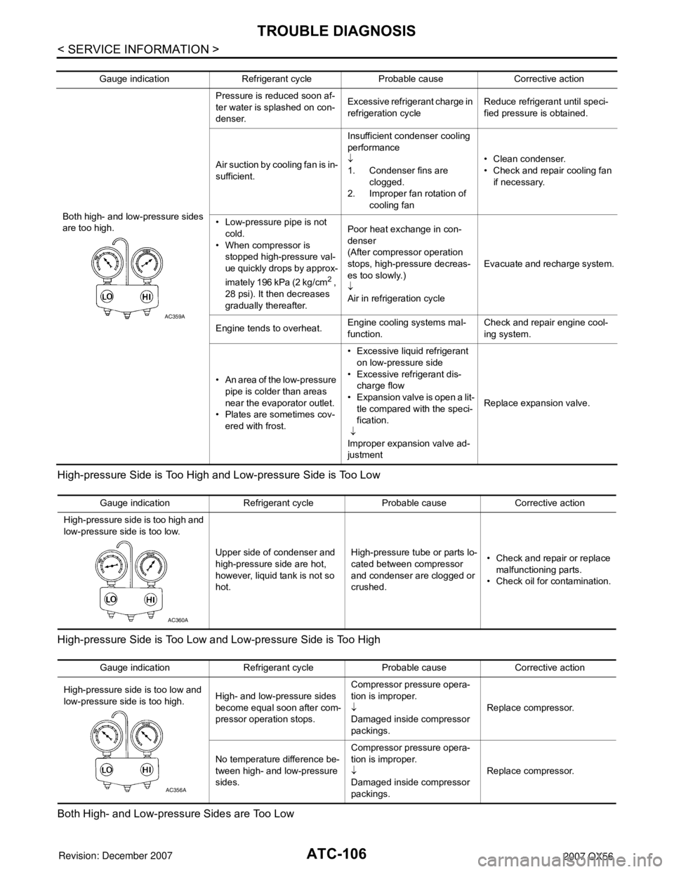
High-pressure Side is Too High and Low-pressure Side is Too Low
High-pressure Side is Too Low and Low-pressure Side is Too High
Both High- and Low-pressure Sides are Too Low
Gauge indication Refrigerant cycle Probable cause Corrective action
Both high- and low-pressure sides
are too high. Pressure is reduced soon af-
ter water is splashed on con-
denser.
Excessive refrigerant charge in
refrigeration cycle
Reduce refrigerant until speci-
fied pressure is obtained.
Air suction by cooling fan is in-
sufficient. Insufficient condenser cooling
performance
↓
1. Condenser fins are
clogged.
2. Improper fan rotation of cooling fan • Clean condenser.
• Check and repair cooling fan
if necessary.
• Low-pressure pipe is not cold.
• When compressor is stopped high-pressure val-
ue quickly drops by approx-
imately 196 kPa (2 kg/cm
2 ,
28 psi). It then decreases
gradually thereafter. Poor heat exchange in con-
denser
(After compressor operation
stops, high-pressure decreas-
es too slowly.)
↓
Air in refrigeration cycle
Evacuate and recharge system.
Engine tends to overheat. Engine cooling systems mal-
function. Check and repair engine cool-
ing system.
• An area of the low-pressure pipe is colder than areas
near the evaporator outlet.
• Plates are sometimes cov- ered with frost. • Excessive liquid refrigerant
on low-pressure side
• Excessive refrigerant dis- charge flow
• Expansion valve is open a lit- tle compared with the speci-
fication.
↓
Improper expansion valve ad-
justment Replace expansion valve.
AC359A
Gauge indication Refrigerant cycle Probable cause Corrective action
High-pressure side is too high and
low-pressure side is too low.
Upper side of condenser and
high-pressure side are hot,
however, liquid tank is not so
hot.High-pressure tu
be or parts lo-
cated between compressor
and condenser are clogged or
crushed. • Check and repair or replace
malfunctioning parts.
• Check oil for contamination.
AC360A
Gauge indication Refrigerant cycle Probable cause Corrective action
High-pressure side is too low and
low-pressure side is too high. High- and low-pressure sides
become equal soon after com-
pressor operation stops.Compressor pressure opera-
tion is improper.
↓
Damaged inside compressor
packings.
Replace compressor.
No temperature difference be-
tween high- and low-pressure
sides. Compressor pressure opera-
tion is improper.
↓
Damaged inside compressor
packings.
Replace compressor.
AC356A
Page 478 of 3061
ATC-108
< SERVICE INFORMATION >
TROUBLE DIAGNOSIS
Insufficient Heating
INFOID:0000000003533261
SYMPTOM: Insufficient heating
INSPECTION FLOW
1.CONFIRM SYMPTOM BY PERFORMING OPER ATIONAL CHECK - TEMPERATURE INCREASE
1. Press the AUTO switch.
2. Turn the temperature control dial (driver) clockwise until 32 ° C (90 ° F) is displayed.
3. Check for hot air at discharge air outlets.
Can this symptom be duplicated?
YES >> GO TO 2.
NO >> Perform complete system operational check. Refer to ATC-50, "
Operational Check (Front)" .
2.CHECK FOR SERVICE BULLETINS
Check for any service bulletins.
>> GO TO 3.
3.PERFORM SELF-DIAGNOSIS
Perform self-diagnosis. Refer to ATC-48, "
A/C System Self-Diagnosis Function" .
OK or NG
OK >> GO TO 4.
NG >> Refer to ATC-48, "
A/C System Self-Diagnosis Function" .
4.CHECK ENGINE COOLING SYSTEM
1. Check for proper engine coolant level. Refer to CO-9, "
Inspection".
2. Check hoses for leaks or kinks.
3. Check radiator cap. Refer to CO-9, "
Inspection" .
4. Check for air in cooling system.
>> GO TO 5.
5.CHECK AIR MIX DOOR OPERATION
Check the operation of the air mix door.
OK or NG
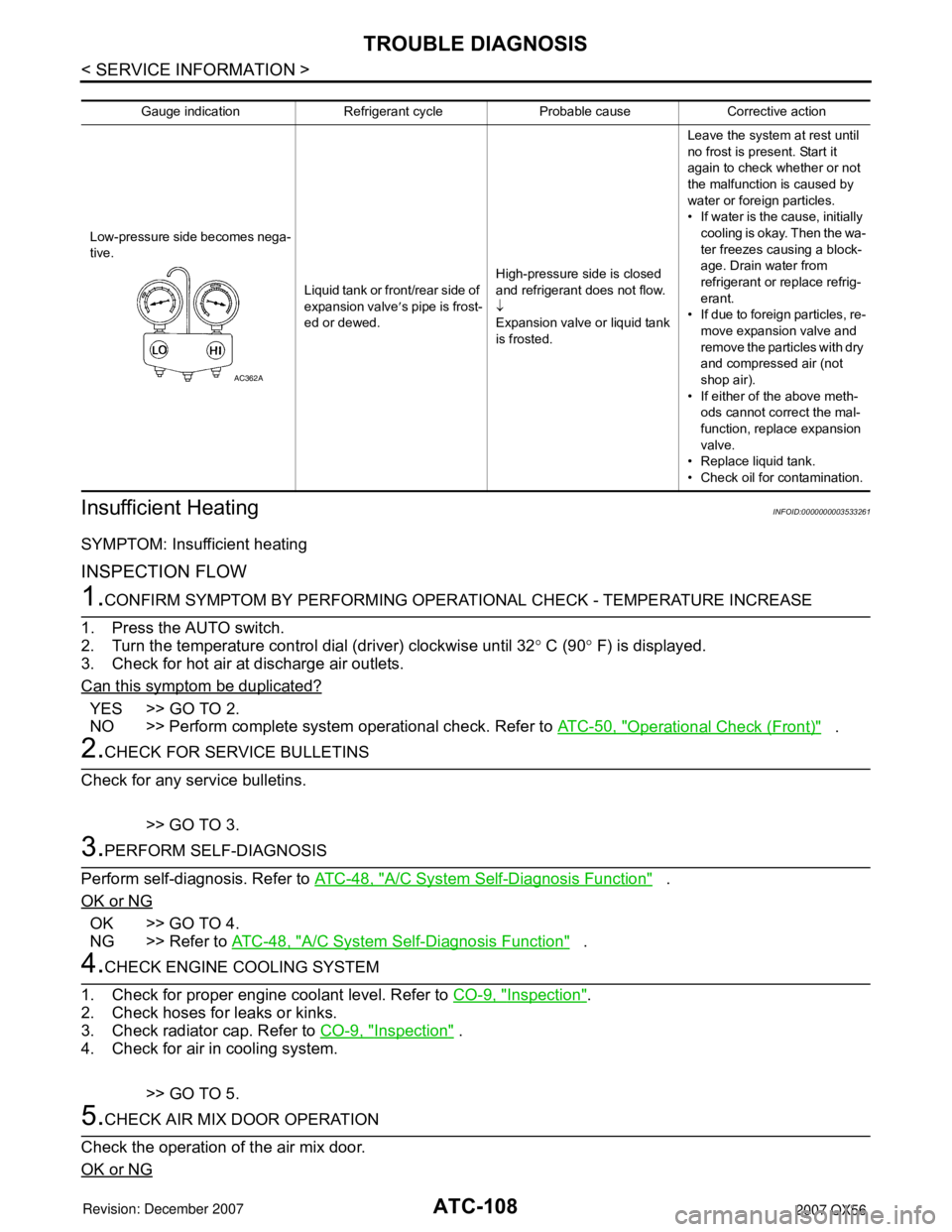
Gauge indication Refrigerant cycle Probable cause Corrective action
Low-pressure side becomes nega-
tive. Liquid tank or front/rear side of
expansion valve′s pipe is frost-
ed or dewed. High-pressure side is closed
and refrigerant does not flow.
↓
Expansion valve or liquid tank
is frosted. Leave the system at rest until
no frost is present. Start it
again to check whether or not
the malfunction is caused by
water or foreign particles.
• If water is the cause, initially
cooling is okay. Then the wa-
ter freezes causing a block-
age. Drain water from
refrigerant or replace refrig-
erant.
• If due to foreign particles, re-
move expansion valve and
remove the particles with dry
and compressed air (not
shop air).
• If either of the above meth- ods cannot correct the mal-
function, replace expansion
valve.
• Replace liquid tank.
• Check oil for contamination.
AC362A
Page 504 of 3061
ATC-134
< SERVICE INFORMATION >
HEATER & COOLING UNIT ASSEMBLY
5. Disconnect the front heater hoses from the front heater core.
6. Disconnect the high/low pressure pipes from the front expansion valve.
7. Remove the instrument panel and console panel. Refer to IP-10, "
Removal and Installation".
8. Remove the steering column. Refer to PS-10
.
9. Disconnect the instrument panel wire harness at the RH and LH in-line connector brackets, and the fuse
block (J/B) electrical connectors. Refer to PG-3
.
10. Disconnect the steering member from each side of the vehicle body.
11. Remove the front heater and cooling unit assembly with it attached to the steering member, from the vehi-
cle.
CAUTION:
Use care not to damage the seats and interior tr im panels when removing the front heater and
cooling unit assembly with it at tached to the steering member.
12. Remove the front heater and cooling unit assembly from the steering member.
Installation
Installation is in the reverse order of removal.
CAUTION:
• Replace the O-ring of the low-pressure pipe and high-pressure pipe with a new one, and apply com-
pressor oil to it when installing it.
• After charging the refrigerant, check for leaks.
NOTE:
• Fill the engine cooling system with the s pecified coolant mixture. Refer to MA-12, "
Changing Engine Cool-
ant".
• Recharge the A/C system. Refer to ATC-150, "
HFC-134a (R-134a) Service Procedure".
REAR HEATER AND COOLING UNIT ASSEMBLY
Removal
1. Discharge the refrigerant from the A/C system. Refer to ATC-150, "HFC-134a (R-134a) Service Proce-
dure".
2. Drain the coolant from the engine cooling system. Refer to MA-12, "
Changing Engine Coolant".
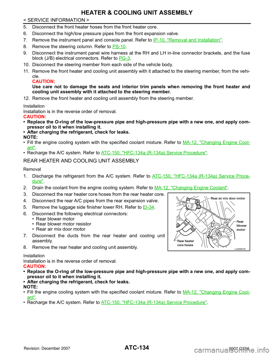
3. Disconnect the rear heater core hoses from the rear heater core.
4. Disconnect the rear A/C pipes from the rear expansion valve.
5. Remove the luggage side finisher lower RH. Refer to EI-34
.
6. Disconnect the following electrical connectors: • Rear blower motor
• Rear blower motor resistor
• Rear air mix door motor
7. Disconnect the ducts from the rear heater and cooling unit assembly.
8. Remove the rear heater and cooling unit assembly.
Installation
Installation is in the reverse order of removal.
CAUTION:
• Replace the O-ring of the low-pressure pipe and high-pressure pipe with a new one, and apply com-
pressor oil to it when installing it.
• After charging the refrigerant, check for leaks.
NOTE:
• Fill the engine cooling system with the s pecified coolant mixture. Refer to MA-12, "
Changing Engine Cool-
ant".
• Recharge the A/C system. Refer to ATC-150, "
HFC-134a (R-134a) Service Procedure".
LJIA0021E
Page 524 of 3061
ATC-154
< SERVICE INFORMATION >
REFRIGERANT LINES
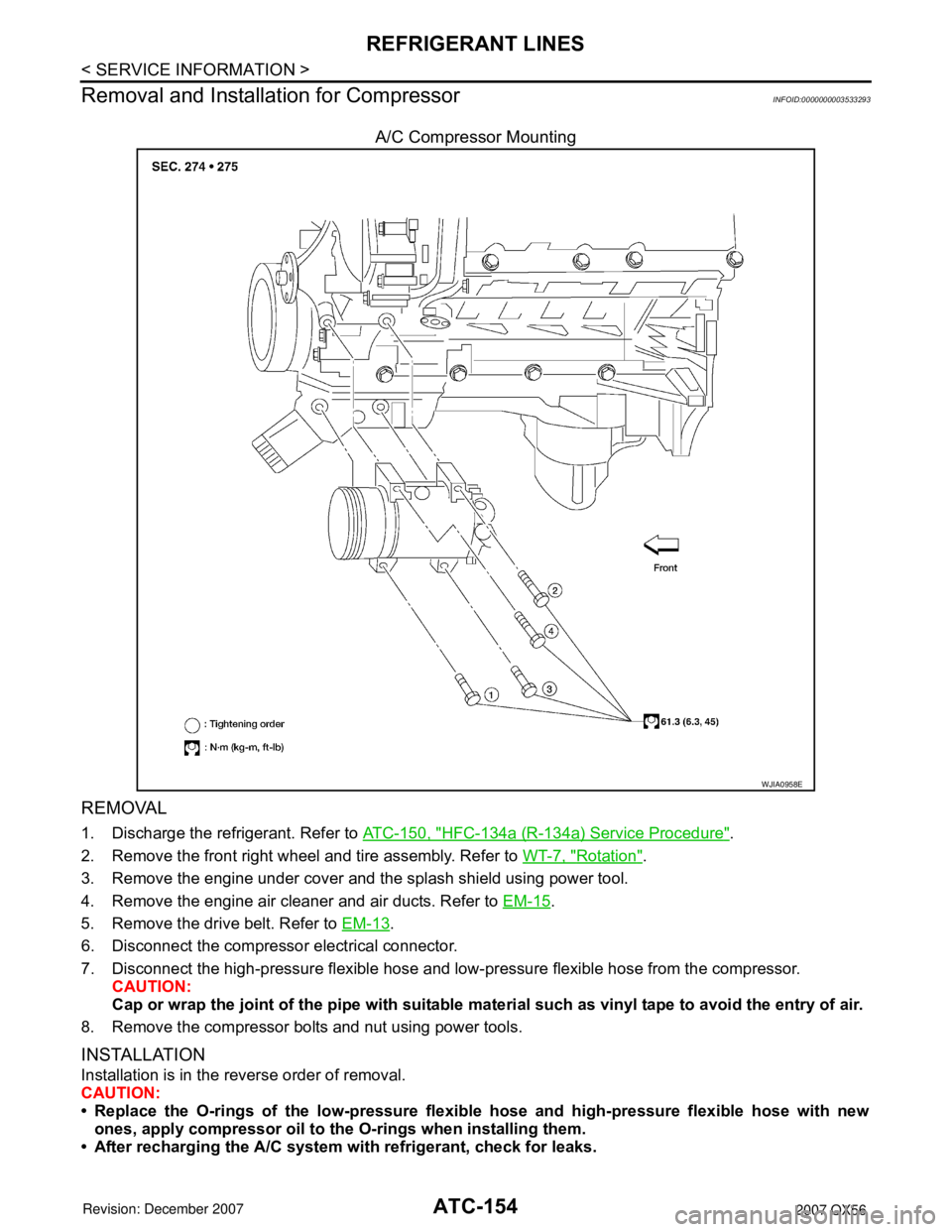
Removal and Installation for Compressor
INFOID:0000000003533293
A/C Compressor Mounting
REMOVAL
1. Discharge the refrigerant. Refer to ATC-150, "HFC-134a (R-134a) Service Procedure".
2. Remove the front right wheel and tire assembly. Refer to WT-7, "
Rotation".
3. Remove the engine under cover and the splash shield using power tool.
4. Remove the engine air cleaner and air ducts. Refer to EM-15
.
5. Remove the drive belt. Refer to EM-13
.
6. Disconnect the compressor electrical connector.
7. Disconnect the high-pressure flexible hose and low- pressure flexible hose from the compressor.
CAUTION:
Cap or wrap the joint of the pipe with suitable mate rial such as vinyl tape to avoid the entry of air.
8. Remove the compressor bolts and nut using power tools.
INSTALLATION
Installation is in the reverse order of removal.
CAUTION:
• Replace the O-rings of the low-pressure flexibl e hose and high-pressure flexible hose with new
ones, apply compressor oil to the O-rings when installing them.
• After recharging the A/C system with refrigerant, check for leaks.
WJIA0958E
Page 528 of 3061
ATC-158
< SERVICE INFORMATION >
REFRIGERANT LINES
BREAK-IN OPERATION
When replacing compressor clutch assembly, always conduct the break-in operation. This is done by engag-
ing and disengaging the clutch about 30 times. Break-in operation raises the level of transmitted torque.
Removal and Installation for Low-Pressure Flexible HoseINFOID:0000000003533295
REMOVAL
1. Remove the engine room cover using power tools.
2. Remove the engine air cleaner and air ducts. Refer to EM-15
.
3. Remove the cowl top extension. Refer to EI-17
.
4. Discharge the refrigerant. Refer to ATC-150, "
HFC-134a (R-134a) Service Procedure".
CAUTION:
Cap or wrap the joint of the pipe with suitable mate rial such as vinyl tape to avoid the entry of air.
5. Remove the low-pressure flexible hose.
INSTALLATION
Installation is in the reverse order of removal.
Refer to ATC-152, "
Component".
CAUTION:
• Replace the O-ring of the low-pr essure flexible hose with a new one, then apply compressor oil to it
when installing it.
• After charging refrigerant, check for leaks.
Removal and Installation for High-pressure Flexible HoseINFOID:0000000003533296
REMOVAL
1. Remove the engine under cover.
2. Remove the engine air cleaner and air ducts. Refer to EM-15
.
3. Discharge the refrigerant. Refer to ATC-150, "
HFC-134a (R-134a) Service Procedure".
4. Remove the high-pressure flexible hose. CAUTION:
Cap or wrap the joint of the pipe with suitable mate rial such as vinyl tape to avoid the entry of air.
INSTALLATION
Installation is in the reverse order of removal.
Refer to ATC-152, "
Component".
CAUTION:
• Replace the O-ring of the high-pressure flexible hose with a new one, then apply compressor oil to it
when installing it.
• After charging refrigerant, check for leaks.
Removal and Installation for High-pressure PipeINFOID:0000000003533297
REMOVAL
1. Remove the cowl top extension. Refer to EI-17.
2. Disconnect the battery negative terminal and positive battery terminal.
3. Reposition the IPDM E/R aside.
4. Remove the front right wheel and tire assembly. Refer to WT-7, "
Rotation".
5. Position aside the front floor insulator.
6. Discharge the refrigerant. Refer to ATC-150, "
HFC-134a (R-134a) Service Procedure".
7. Remove the low-pressure pipe. Refer to ATC-159, "
Removal and Installation for Low-Pressure Pipe".
8. Remove the high-pressure pipe. CAUTION:
Cap or wrap the joint of the pipe with suitable mate rial such as vinyl tape to avoid the entry of air.
INSTALLATION
Installation is in the reverse order of removal.
Page 529 of 3061
REFRIGERANT LINESATC-159
< SERVICE INFORMATION >
C
DE
F
G H
I
K L
M A
B
AT C
N
O P
Refer to ATC-152, "Component".
CAUTION:
• Replace the O-ring of the high-pressure pipe with a new one, then apply compressor oil to it when
installing it.
• After charging refrigerant, check for leaks.
Removal and Installation for Low-Pressure PipeINFOID:0000000003533298
REMOVAL
1. Discharge the refrigerant. Refer to ATC-150, "HFC-134a (R-134a) Service Procedure".
2. Remove the cowl top and the cowl top extension. Refer to EI-17
.
3. Remove the low-pressure pipe. CAUTION:
Cap or wrap the joint of the pipes with suitable material such as viny l tape to avoid the entry of air.
INSTALLATION
Installation is in the reverse order of removal.
Refer to ATC-152, "
Component".
CAUTION:
• Replace the O-ring of the high/low-pressure pipe with a new one, then apply compressor oil to it
when installing it.
• After charging refrigerant, check for leaks.
Removal and Installation for Rear High- and Low-Pressure A/C and Heater Core Pipes
INFOID:0000000003533299
REMOVAL
1. Discharge the refrigerant. Refer to ATC-150, "HFC-134a (R-134a) Service Procedure".
2. Drain the coolant from the engine cooling system. Refer to CO-9, "
Changing Engine Coolant".
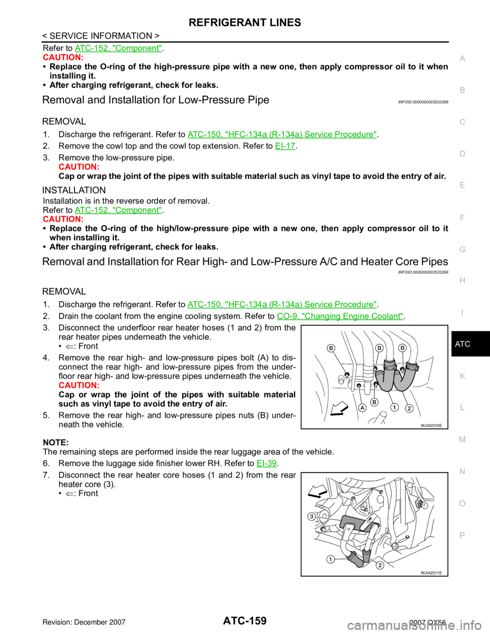
3. Disconnect the underfloor rear heater hoses (1 and 2) from the rear heater pipes underneath the vehicle.
•⇐ : Front
4. Remove the rear high- and low-pressure pipes bolt (A) to dis- connect the rear high- and low-pressure pipes from the under-
floor rear high- and low-pressu re pipes underneath the vehicle.
CAUTION:
Cap or wrap the joint of the pipes with suitable material
such as vinyl tape to avo id the entry of air.
5. Remove the rear high- and low-pressure pipes nuts (B) under- neath the vehicle.
NOTE:
The remaining steps are performed inside the rear luggage area of the vehicle.
6. Remove the luggage side finisher lower RH. Refer to EI-39
.
7. Disconnect the rear heater core hoses (1 and 2) from the rear heater core (3).
•⇐ : Front
WJIA2310E
WJIA2311E
Page 530 of 3061
ATC-160
< SERVICE INFORMATION >
REFRIGERANT LINES
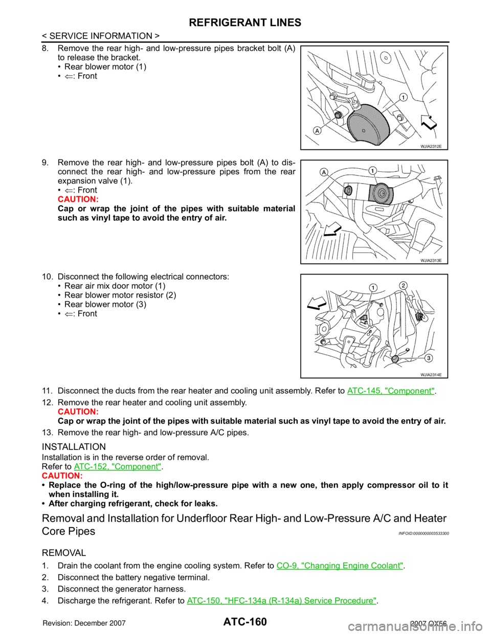
8. Remove the rear high- and low-pressure pipes bracket bolt (A)to release the bracket.
• Rear blower motor (1)
•⇐ : Front
9. Remove the rear high- and low-pressure pipes bolt (A) to dis- connect the rear high- and low-pressure pipes from the rear
expansion valve (1).
•⇐ : Front
CAUTION:
Cap or wrap the joint of the pipes with suitable material
such as vinyl tape to avoid the entry of air.
10. Disconnect the following electrical connectors: • Rear air mix door motor (1)
• Rear blower motor resistor (2)
• Rear blower motor (3)
•⇐ : Front
11. Disconnect the ducts from the rear heater and cooling unit assembly. Refer to ATC-145, "
Component".
12. Remove the rear heater and cooling unit assembly. CAUTION:
Cap or wrap the joint of the pipes with suitable material such as viny l tape to avoid the entry of air.
13. Remove the rear high- and low-pressure A/C pipes.
INSTALLATION
Installation is in the reverse order of removal.
Refer to ATC-152, "
Component".
CAUTION:
• Replace the O-ring of th e high/low-pressure pipe with a new one, then apply compressor oil to it
when installing it.
• After charging refrigerant, check for leaks.
Removal and Installati on for Underfloor Rear High- and Low-Pressure A/C and Heater
Core Pipes
INFOID:0000000003533300
REMOVAL
1. Drain the coolant from the engine cooling system. Refer to CO-9, "Changing Engine Coolant".
2. Disconnect the battery negative terminal.
3. Disconnect the generator harness.
4. Discharge the refrigerant. Refer to ATC-150, "
HFC-134a (R-134a) Service Procedure".
WJIA2312E
WJIA2313E
WJIA2314E
Page 537 of 3061
REFRIGERANT LINESATC-167
< SERVICE INFORMATION >
C
DE
F
G H
I
K L
M A
B
AT C
N
O P
If repairing the A/C system or replacing a com ponent, pour the HFC-134a (R-134a) fluorescent leak
detection dye (J-41447) directly into the open system connection and proceed with the service
procedures.
3. Connect the refrigerant dye injector (J- 41459) to the low-pressure service valve.
4. Start the engine and switch the A/C system ON.
5. When the A/C system is operating (compressor runni ng), inject one bottle 7.4 cc (1/4 ounce) of HFC-134a
(R-134a) fluorescent leak detection dye (J-41447) th rough the low-pressure service valve using HFC-
134a (R-134a) dye injector (J-41459). Refer to the manufacturer's operating instructions.
6. With the engine still running, disconnect the HFC-134a (R -134a) dye injector (J-41459) from the low-pres-
sure service valve.
7. Operate the A/C system for a minimum of 20 minut es to mix the HFC-134a (R-134a) fluorescent leak
detection dye (J-41447) with the A/C system oil. Depending on the leak size, operating conditions and
location of the leak, it may take from minutes to days for the HFC-134a (R-134a) fluorescent leak detec-
tion dye to penetrate an A/C system leak and become visible.
Electronic Refrigerant Leak DetectorINFOID:0000000003533310
PRECAUTIONS FOR HANDLING LEAK DETECTOR
NOTE:
When performing a refrigerant leak check, use a electr onic refrigerant leak detector (J-41995) or equivalent.
Ensure that the electronic refrigerant leak detector (J-41995) is calibrated and set properly according to the
manufacturer's operating instructions.
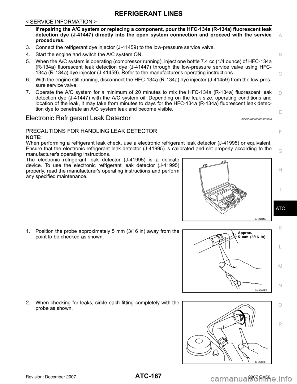
The electronic refrigerant leak detector (J-41995) is a delicate
device. To use the electronic refrigerant leak detector (J-41995)
properly, read the manufacturer's operating instructions and perform
any specified maintenance.
1. Position the probe approximately 5 mm (3/16 in) away from the point to be checked as shown.
2. When checking for leaks, circle each fitting completely with the probe as shown.
AHA281A
SHA707EA
SHA706E
Page 540 of 3061
ATC-170
< SERVICE INFORMATION >
SERVICE DATA AND SPECIFICATIONS (SDS)
SERVICE DATA AND SPECIFICATIONS (SDS)
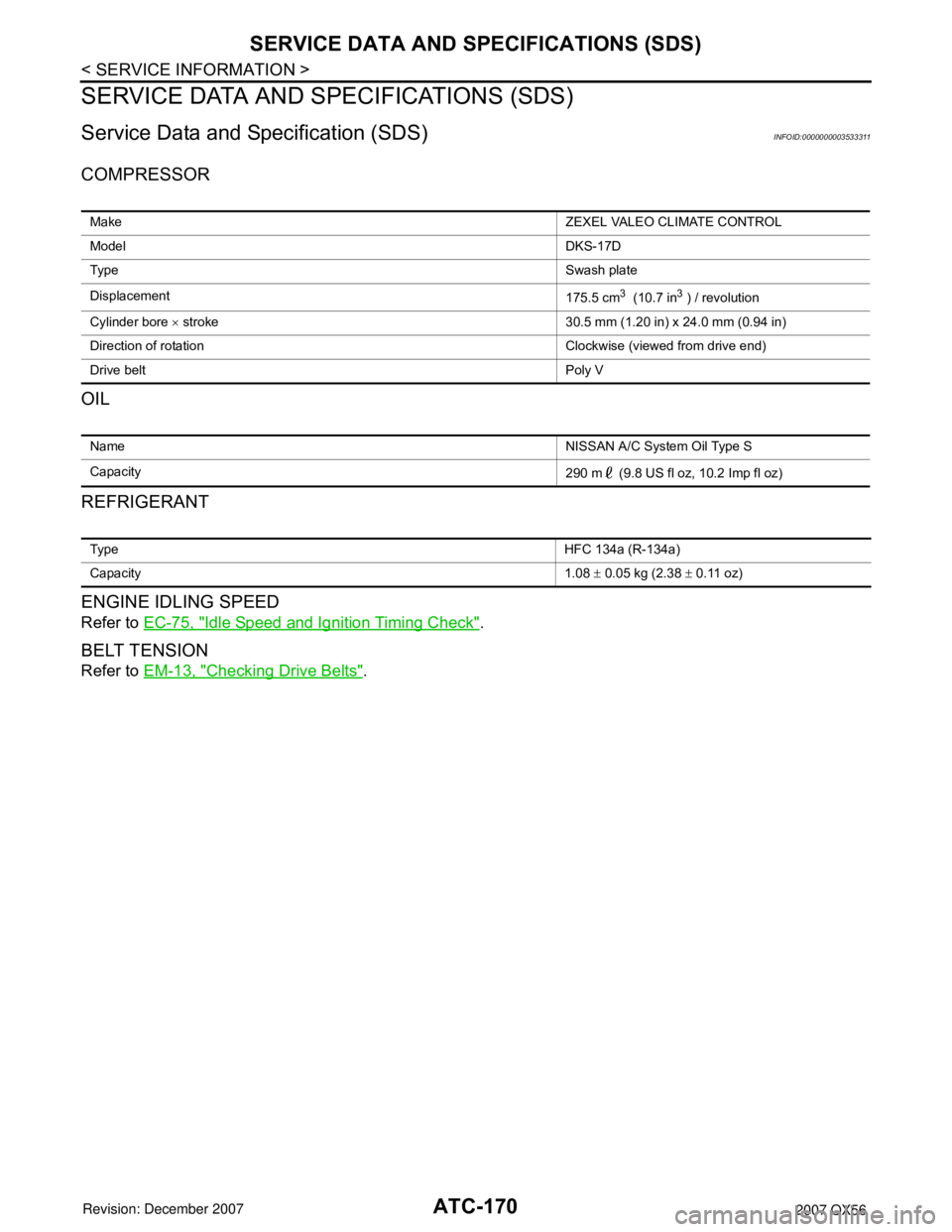
Service Data and Specification (SDS)INFOID:0000000003533311
COMPRESSOR
OIL
REFRIGERANT
ENGINE IDLING SPEED
Refer to EC-75, "Idle Speed and Ignition Timing Check".
BELT TENSION
Refer to EM-13, "Checking Drive Belts".
Make ZEXEL VALEO CLIMATE CONTROL
Model DKS-17D
Ty p e Swash plate
Displacement 175.5 cm
3 (10.7 in3 ) / revolution
Cylinder bore × stroke 30.5 mm (1.20 in) x 24.0 mm (0.94 in)
Direction of rotation Clockwise (viewed from drive end)
Drive belt Poly V
Name NISSAN A/C System Oil Type S
Capacity 290 m (9.8 US fl oz, 10.2 Imp fl oz)
Ty p eHFC 134a (R-134a)
Capacity 1.08 ± 0.05 kg (2.38 ± 0.11 oz)
Page 571 of 3061
AUDIO
AV-31
< SERVICE INFORMATION >
C
D
E
F
G
H
I
J
L
MA
B
AV
N
O
P
• Loss of power to the satellite radio tuner (factory installed)
• Open or short in the REQ1, TXD, or RXD circuits.
If the satellite antenna is disconnected or inoperative, the display unit will display ANTENNA.
Noise InspectionINFOID:0000000003533674
The vehicle itself can be a source of noise if noise prevention parts or electrical equipment is malfunctioning.
Check if noise is caused and/or changed by engine speed, ignition switch turned to each position, and opera-
tion of each piece of electrical equipment, and determine the cause.
NOTE:
The source of the noise can be found easily by listening to the noise while removing the fuses of electrical
components, one by one.
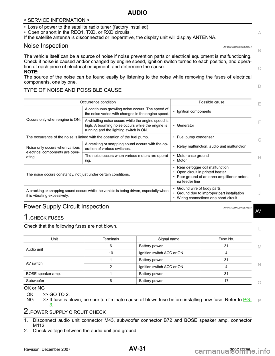
TYPE OF NOISE AND POSSIBLE CAUSE
Power Supply Circuit InspectionINFOID:0000000003533675
1.CHECK FUSES
Check that the following fuses are not blown.
OK or NG
OK >> GO TO 2.
NG >> If fuse is blown, be sure to eliminate cause of blown fuse before installing new fuse. Refer to PG-
3.
2.POWER SUPPLY CIRCUIT CHECK
1. Disconnect audio unit connector M43, subwoofer connector B72 and BOSE speaker amp. connector
M112.
2. Check voltage between the audio unit and ground.
Occurrence condition Possible cause
Occurs only when engine is ON.A continuous growling noise occurs. The speed of
the noise varies with changes in the engine speed.• Ignition components
A whistling noise occurs while the engine speed is
high. A booming noise occurs while the engine is
running and the lighting switch is ON.• Generator
The occurrence of the noise is linked with the operation of the fuel pump. • Fuel pump condenser
Noise only occurs when various
electrical components are oper-
ating.A cracking or snapping sound occurs with the op-
eration of various switches.• Relay malfunction, audio unit malfunction
The noise occurs when various motors are operat-
ing.• Motor case ground
•Motor
The noise occurs constantly, not just under certain conditions.• Rear defogger coil malfunction
• Open circuit in printed heater
• Poor ground of antenna amplifier or anten-
na feeder line
A cracking or snapping sound occurs while the vehicle is being driven, especially when
it is vibrating excessively.• Ground wire of body parts
• Ground due to improper part installation
• Wiring connections or a short circuit
Unit Terminals Signal name Fuse No.
Audio unit6 Battery power 31
10 Ignition switch ACC or ON 4
AV switch1 Battery power 31
2 Ignition switch ACC or ON 4
BOSE speaker amp. 1 Battery power 31
Subwoofer 6 Battery power 17