torque INFINITI QX56 2007 Factory Manual Online
[x] Cancel search | Manufacturer: INFINITI, Model Year: 2007, Model line: QX56, Model: INFINITI QX56 2007Pages: 3061, PDF Size: 64.56 MB
Page 1232 of 3061
DTC P0011, P0021 IVT CONTROL
EC-149
< SERVICE INFORMATION >
C
D
E
F
G
H
I
J
K
L
MA
EC
N
P O
DTC P0011, P0021 IVT CONTROL
DescriptionINFOID:0000000003531648
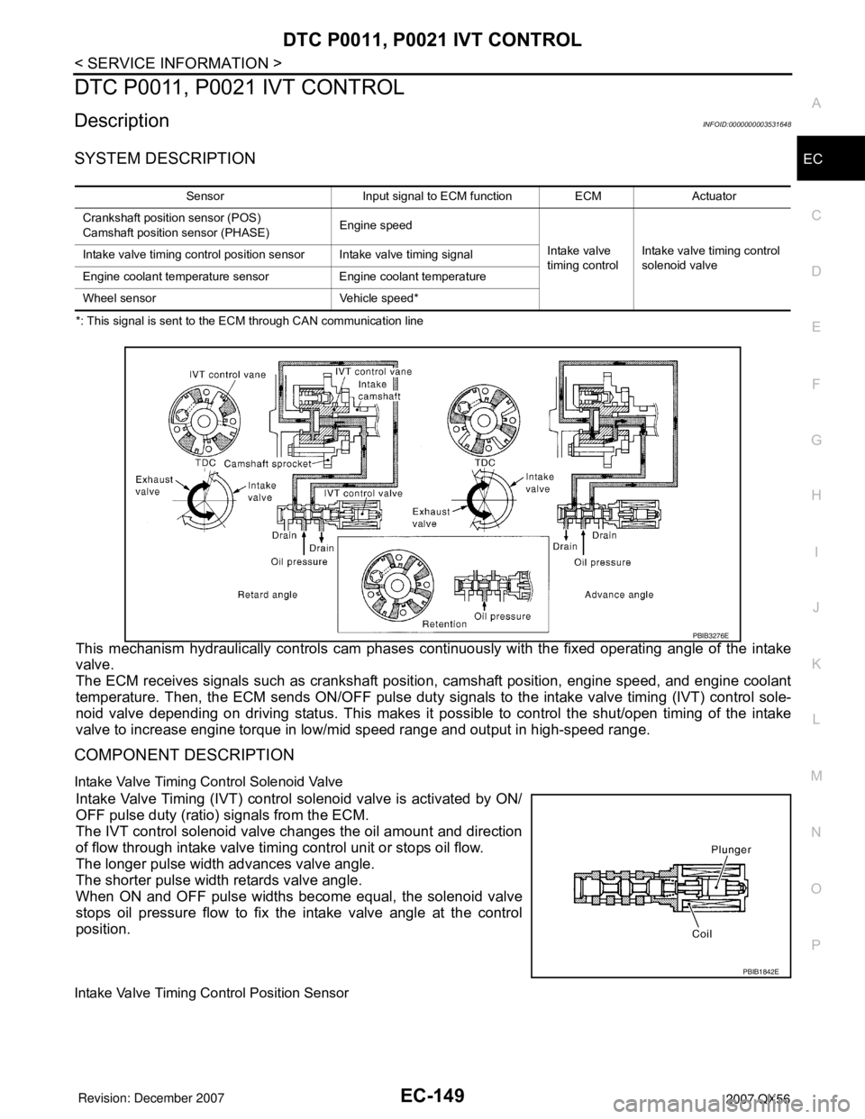
SYSTEM DESCRIPTION
*: This signal is sent to the ECM through CAN communication line
This mechanism hydraulically controls cam phases continuously with the fixed operating angle of the intake
valve.
The ECM receives signals such as crankshaft position, camshaft position, engine speed, and engine coolant
temperature. Then, the ECM sends ON/OFF pulse duty signals to the intake valve timing (IVT) control sole-
noid valve depending on driving status. This makes it possible to control the shut/open timing of the intake
valve to increase engine torque in low/mid speed range and output in high-speed range.
COMPONENT DESCRIPTION
Intake Valve Timing Control Solenoid Valve
Intake Valve Timing (IVT) control solenoid valve is activated by ON/
OFF pulse duty (ratio) signals from the ECM.
The IVT control solenoid valve changes the oil amount and direction
of flow through intake valve timing control unit or stops oil flow.
The longer pulse width advances valve angle.
The shorter pulse width retards valve angle.
When ON and OFF pulse widths become equal, the solenoid valve
stops oil pressure flow to fix the intake valve angle at the control
position.
Intake Valve Timing Control Position Sensor
Sensor Input signal to ECM function ECM Actuator
Crankshaft position sensor (POS)
Camshaft position sensor (PHASE)Engine speed
Intake valve
timing controlIntake valve timing control
solenoid valve Intake valve timing control position sensor Intake valve timing signal
Engine coolant temperature sensor Engine coolant temperature
Wheel sensor Vehicle speed*
PBIB3276E
PBIB1842E
Page 1339 of 3061
EC-256
< SERVICE INFORMATION >
DTC P0133, P0153 A/F SENSOR 1
: Average voltage for pulse signal (Actual pulse signal can be confirmed by oscilloscope.)
Diagnosis ProcedureINFOID:0000000003531763
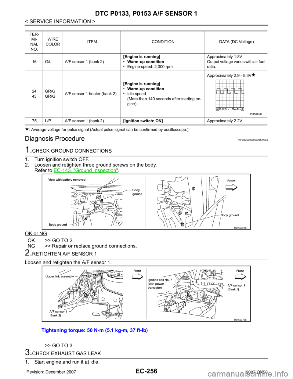
1.CHECK GROUND CONNECTIONS
1. Turn ignition switch OFF.
2. Loosen and retighten three ground screws on the body.
Refer to EC-143, "
Ground Inspection".
OK or NG
OK >> GO TO 2.
NG >> Repair or replace ground connections.
2.RETIGHTEN A/F SENSOR 1
Loosen and retighten the A/F sensor 1.
>> GO TO 3.
3.CHECK EXHAUST GAS LEAK
1. Start engine and run it at idle.
TER-
MI-
NAL
NO.WIRE
COLORITEM CONDITION DATA (DC Voltage)
16 G/L A/F sensor 1 (bank 2)[Engine is running]
•Warm-up condition
• Engine speed: 2,000 rpmApproximately 1.8V
Output voltage varies with air fuel
ratio.
24
43GR/G
GR/GA/F sensor 1 heater (bank 2)[Engine is running]
•Warm-up condition
• Idle speed
(More than 140 seconds after starting en-
gine)Approximately 2.9 - 8.8V
75 L/P A/F sensor 1 (bank 2)[Ignition switch: ON]Approximately 2.2V
PBIA8148J
BBIA0354E
Tightening torque: 50 N-m (5.1 kg-m, 37 ft-lb)
BBIA0375E
Page 1676 of 3061
DTC P2A00, P2A03 A/F SENSOR 1
EC-593
< SERVICE INFORMATION >
C
D
E
F
G
H
I
J
K
L
MA
EC
N
P O
: Average voltage for pulse signal (Actual pulse signal can be confirmed by oscilloscope.)
Diagnosis ProcedureINFOID:0000000003532146
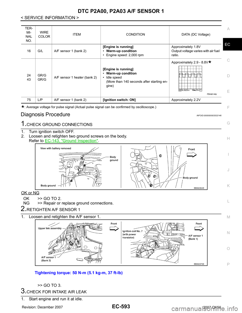
1.CHECK GROUND CONNECTIONS
1. Turn ignition switch OFF.
2. Loosen and retighten two ground screws on the body.
Refer to EC-143, "
Ground Inspection".
OK or NG
OK >> GO TO 2.
NG >> Repair or replace ground connections.
2.RETIGHTEN A/F SENSOR 1
1. Loosen and retighten the A/F sensor 1.
>> GO TO 3.
3.CHECK FOR INTAKE AIR LEAK
1. Start engine and run it at idle.
TER-
MI-
NAL
NO.WIRE
COLORITEM CONDITION DATA (DC Voltage)
16 G/L A/F sensor 1 (bank 2)[Engine is running]
•Warm-up condition
• Engine speed: 2,000 rpmApproximately 1.8V
Output voltage varies with air fuel
ratio.
24
43GR/G
GR/GA/F sensor 1 heater (bank 2)[Engine is running]
•Warm-up condition
• Idle speed
(More than 140 seconds after starting en-
gine)Approximately 2.9 - 8.8V
75 L/P A/F sensor 1 (bank 2)[Ignition switch: ON]Approximately 2.2V
PBIA8148J
BBIA0354E
Tightening torque: 50 N-m (5.1 kg-m, 37 ft-lb)
BBIA0375E
Page 1773 of 3061
PRECAUTIONSEM-3
< SERVICE INFORMATION >
C
DE
F
G H
I
J
K L
M A
EM
NP
O
SERVICE INFORMATION
PRECAUTIONS
Precaution for Supplemental
Restraint System (SRS) "AIR BAG" and "SEAT BELT
PRE-TENSIONER"
INFOID:0000000003531508
The Supplemental Restraint System such as “A IR BAG” and “SEAT BELT PRE-TENSIONER”, used along
with a front seat belt, helps to reduce the risk or severi ty of injury to the driver and front passenger for certain
types of collision. This system includes seat belt switch inputs and dual stage front air bag modules. The SRS
system uses the seat belt switches to determine the front air bag deployment, and may only deploy one front
air bag, depending on the severity of a collision and w hether the front occupants are belted or unbelted.
Information necessary to service the system safely is included in the SRS and SB section of this Service Man-
ual.
WARNING:
• To avoid rendering the SRS inoper ative, which could increase the risk of personal injury or death in
the event of a collision which would result in air bag inflation, all maintenance must be performed by
an authorized NISSAN/INFINITI dealer.
• Improper maintenance, including in correct removal and installation of the SRS, can lead to personal
injury caused by unintentional act ivation of the system. For removal of Spiral Cable and Air Bag
Module, see the SRS section.
• Do not use electrical test equipm ent on any circuit related to the SRS unless instructed to in this
Service Manual. SRS wiring harnesses can be identi fied by yellow and/or orange harnesses or har-
ness connectors.
Precaution for Drain Engine CoolantINFOID:0000000003531509
Drain engine coolant when engine is cooled.
Precaution for Disco nnecting Fuel PipingINFOID:0000000003531510
• Before starting work, make sure no fire or spark producing items are in the work area.
• Release fuel pressure before disconnecting and disassembly.
• After disconnecting pipes, plug openings to stop fuel leakage.
Precaution for Removal and DisassemblyINFOID:0000000003531511
• When instructed to use special service tools, use the spec ified tools. Always be careful to work safely, avoid
forceful or uninstructed operations.
• Exercise maximum care to avoid damage to mating or sliding surfaces.
• Cover openings of engine system with tape or the equiva lent, if necessary, to seal out foreign materials.
• Mark and arrange disassembly parts in an organized way for easy troubleshooting and assembly.
• When loosening nuts and bolts, as a basic rule, start with the one furthest outside, then the one diagonally
opposite, and so on. If the order of loosening is specif ied, do exactly as specified. Power tools may be used
where noted in the step.
Precaution for Inspection, Repair and ReplacementINFOID:0000000003531512
Before repairing or replacing, thoroughly inspect parts. Inspect new replacement parts in the same way, and
replace if necessary.
Precaution for Assembly and InstallationINFOID:0000000003531513
• Use torque wrench to tighten bolts or nuts to specification.
• When tightening nuts and bolts, as a basic rule, equally tighten in several different steps starting with the ones in center, then ones on inside and outside diagonally in this order. If the order of tightening is specified,
do exactly as specified.
• Replace with new gasket, packing, oil seal or O-ring.
• Thoroughly wash, clean, and air-blow each part. Carefully check engine oil or engine coolant passages for any restriction and blockage.
• Avoid damaging sliding or mating surfaces. Completely remove foreign materials such as cloth lint or dust. Before assembly, oil sliding surfaces well.
Page 1774 of 3061
EM-4
< SERVICE INFORMATION >
PRECAUTIONS
• Release air within route when refilling after draining engine coolant.
• Before starting engine, apply fuel pressure to fuel lines with turning ignition switch ON (with engine stopped).
Then make sure that there are no leaks at fuel line connections.
• After repairing, start engine and increase engine s peed to check engine coolant, fuel, oil, and exhaust sys-
tems for leakage.
Parts Requiring Angular TighteningINFOID:0000000003531514
• For final tightening of the following engine parts use Tool:
- Cylinder head bolts
- Main bearing cap bolts
- Connecting rod cap bolts
- Crankshaft pulley bolt (No angle wrench is required as the bolt flange is provided with notches for angle tightening)
• Do not use a torque value for final tightening.
• The torque value for these parts are for a preliminary step.
• Ensure thread and seat surfaces are clean and lightly coated with engine oil.
Precaution for Liquid GasketINFOID:0000000003531515
REMOVAL OF LIQUID GASKET SEALING
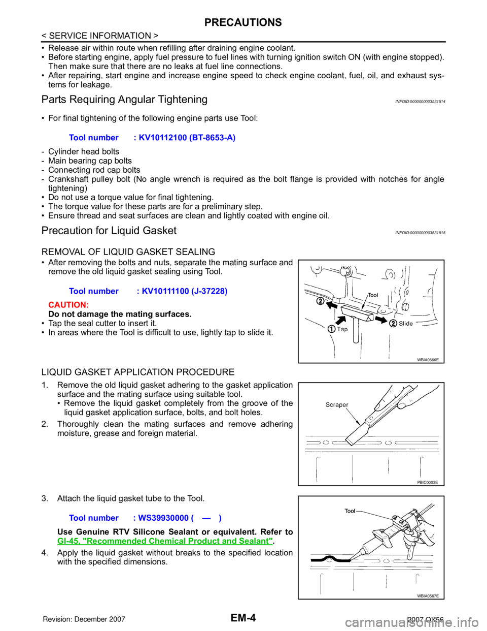
• After removing the bolts and nuts, separate the mating surface and
remove the old liquid gasket sealing using Tool.
CAUTION:
Do not damage the mating surfaces.
• Tap the seal cutter to insert it.
• In areas where the Tool is difficult to use, lightly tap to slide it.
LIQUID GASKET APPLICATION PROCEDURE
1. Remove the old liquid gasket adhering to the gasket application surface and the mating surface using suitable tool.
• Remove the liquid gasket completely from the groove of theliquid gasket application surface, bolts, and bolt holes.
2. Thoroughly clean the mating surfaces and remove adhering moisture, grease and foreign material.
3. Attach the liquid gasket tube to the Tool. Use Genuine RTV Silicone Seal ant or equivalent. Refer to
GI-45, "
Recommended Chemical Product and Sealant".
4. Apply the liquid gasket without breaks to the specified location with the specified dimensions.Tool number : KV10112100 (BT-8653-A)
Tool number : KV10111100 (J-37228)
WBIA0566E
PBIC0003E
Tool number : WS39930000 ( — )
WBIA0567E
Page 1793 of 3061
EXHAUST MANIFOLD AND THREE WAY CATALYST
EM-23
< ON-VEHICLE REPAIR >
C
D E
F
G H
I
J
K L
M A
EM
NP
O
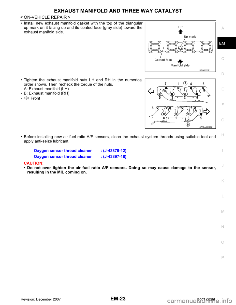
• Install new exhaust manifold gasket with the top of the triangular
up mark on it facing up and its coated face (gray side) toward the
exhaust manifold side.
• Tighten the exhaust manifold nuts LH and RH in the numerical order shown. Then recheck the torque of the nuts.
- A: Exhaust manifold (LH)
- B: Exhaust manifold (RH)
- : Front
• Before installing new air fuel ratio A/F sensors, clean the exhaust system threads using suitable tool and
apply anti-seize lubricant.
CAUTION:
• Do not over tighten the air fuel ratio A/F sen sors. Doing so may cause damage to the sensor,
resulting in the MIL coming on.
KBIA2553E
AWBIA0814ZZ
Oxygen sensor thread cleaner : (J-43879-12)
Oxygen sensor thread cleaner : (J-43897-18)
Page 1814 of 3061
EM-44
< SERVICE INFORMATION >
TIMING CHAIN
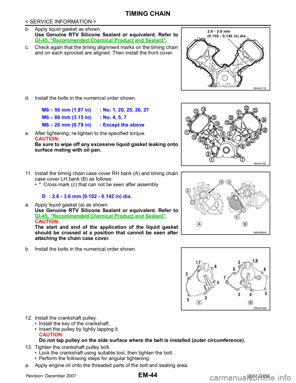
b. Apply liquid gasket as shown.Use Genuine RTV Silicone Seal ant or equivalent. Refer to
GI-45, "
Recommended Chemical Product and Sealant".
c. Check again that the timing alignment marks on the timing chain and on each sprocket are aligned. Then install the front cover.
d. Install the bolts in the numerical order shown.
e. After tightening, re-tighten to the specified torque. CAUTION:
Be sure to wipe off any excessive liquid gasket leaking onto
surface mating with oil pan.
11. Install the timing chain case cover RH bank (A) and timing chain case cover LH bank (B) as follows:
• *: Cross mark (c) that can not be seen after assembly
a. Apply liquid gasket (a) as shown. Use Genuine RTV Silicone Seal ant or equivalent. Refer to
GI-45, "
Recommended Chemical Product and Sealant".
CAUTION:
The start and end of the appl ication of the liquid gasket
should be crossed at a position that cannot be seen after
attaching the chain case cover.
b. Install the bolts in the numerical order shown.
12. Install the crankshaft pulley. • Install the key of the crankshaft.
• Insert the pulley by lightly tapping it.
CAUTION:
Do not tap pulley on the side surface where th e belt is installed (outer circumference).
13. Tighten the crankshaft pulley bolt. • Lock the crankshaft using suitable tool, then tighten the bolt.
• Perform the following steps for angular tightening:
a. Apply engine oil onto the threaded parts of the bolt and seating area.
KBIA2517E
M6 × 50 mm (1.97 in) : No. 1, 20, 25, 26, 27
M6 × 80 mm (3.15 in) : No. 4, 5, 7
M6 × 20 mm (0.79 in) : Except the above
KBIA2478E
D : 2.6 - 3.6 mm (0.102 - 0.142 in) dia.
WBIA0800E
WBIA0798E
Page 1815 of 3061
TIMING CHAINEM-45
< SERVICE INFORMATION >
C
DE
F
G H
I
J
K L
M A
EM
NP
O
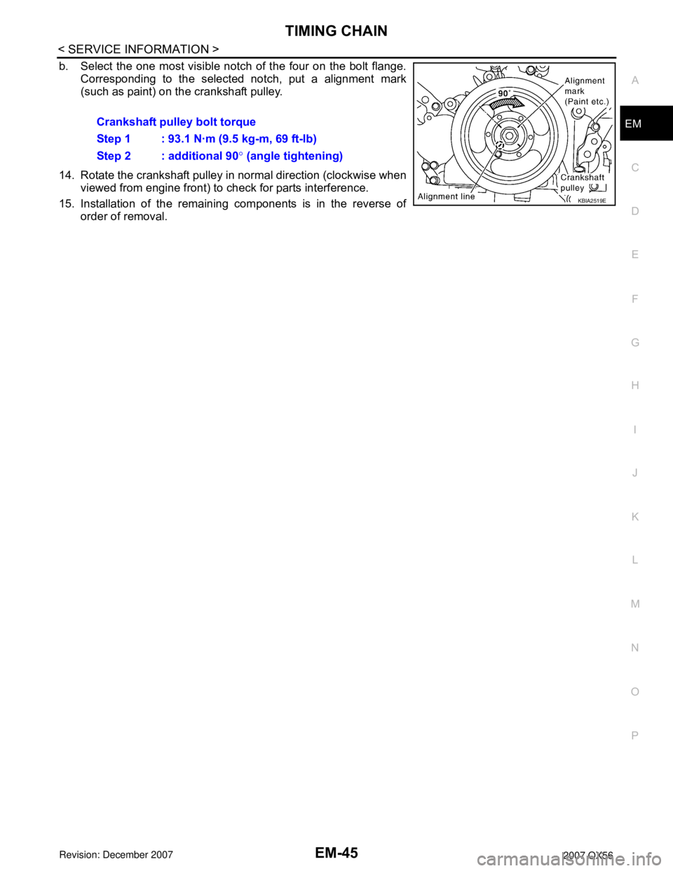
b. Select the one most visible notch of the four on the bolt flange.
Corresponding to the selected notch, put a alignment mark
(such as paint) on the crankshaft pulley.
14. Rotate the crankshaft pulley in normal direction (clockwise when viewed from engine front) to check for parts interference.
15. Installation of the remaining components is in the reverse of order of removal.Crankshaft pulley bolt torque
Step 1 : 93.1 N·m (9.5 kg-m, 69 ft-lb)
Step 2 : additional 90
° (angle tightening)
KBIA2519E
Page 1820 of 3061
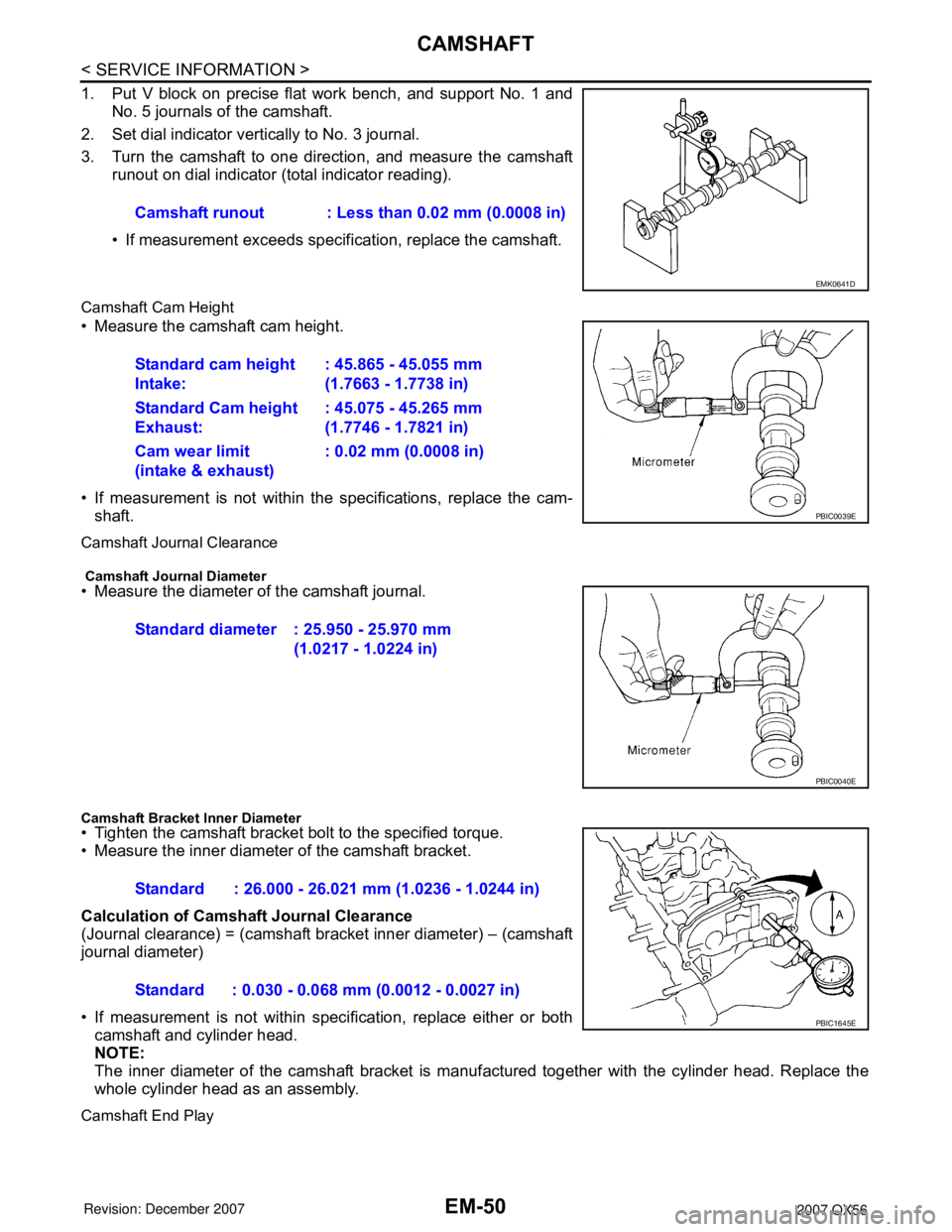
EM-50
< SERVICE INFORMATION >
CAMSHAFT
1. Put V block on precise flat work bench, and support No. 1 andNo. 5 journals of the camshaft.
2. Set dial indicator vertically to No. 3 journal.
3. Turn the camshaft to one direction, and measure the camshaft runout on dial indicator (total indicator reading).
• If measurement exceeds specif ication, replace the camshaft.
Camshaft Cam Height
• Measure the camshaft cam height.
• If measurement is not within the specifications, replace the cam-
shaft.
Camshaft Journal Clearance
Camshaft Journal Diameter• Measure the diameter of the camshaft journal.
Camshaft Bracket Inner Diameter• Tighten the camshaft bracket bolt to the specified torque.
• Measure the inner diameter of the camshaft bracket.
Calculation of Camshaft Journal Clearance
(Journal clearance) = (camshaft bracket inner diameter) – (camshaft
journal diameter)
• If measurement is not within spec ification, replace either or both
camshaft and cylinder head.
NOTE:
The inner diameter of the camshaft bracket is manuf actured together with the cylinder head. Replace the
whole cylinder head as an assembly.
Camshaft End Play
Camshaft runout : Less than 0.02 mm (0.0008 in)
EMK0641D
Standard cam height
Intake: : 45.865 - 45.055 mm
(1.7663 - 1.7738 in)
Standard Cam height
Exhaust: : 45.075 - 45.265 mm
(1.7746 - 1.7821 in)
Cam wear limit
(intake & exhaust) : 0.02 mm (0.0008 in)
PBIC0039E
Standard diameter : 25.950 - 25.970 mm
(1.0217 - 1.0224 in)
PBIC0040E
Standard : 26.000 - 26.021 mm (1.0236 - 1.0244 in)
Standard : 0.030 - 0.068 mm (0.0012 - 0.0027 in)
PBIC1645E
Page 1824 of 3061
EM-54
< SERVICE INFORMATION >
CAMSHAFT
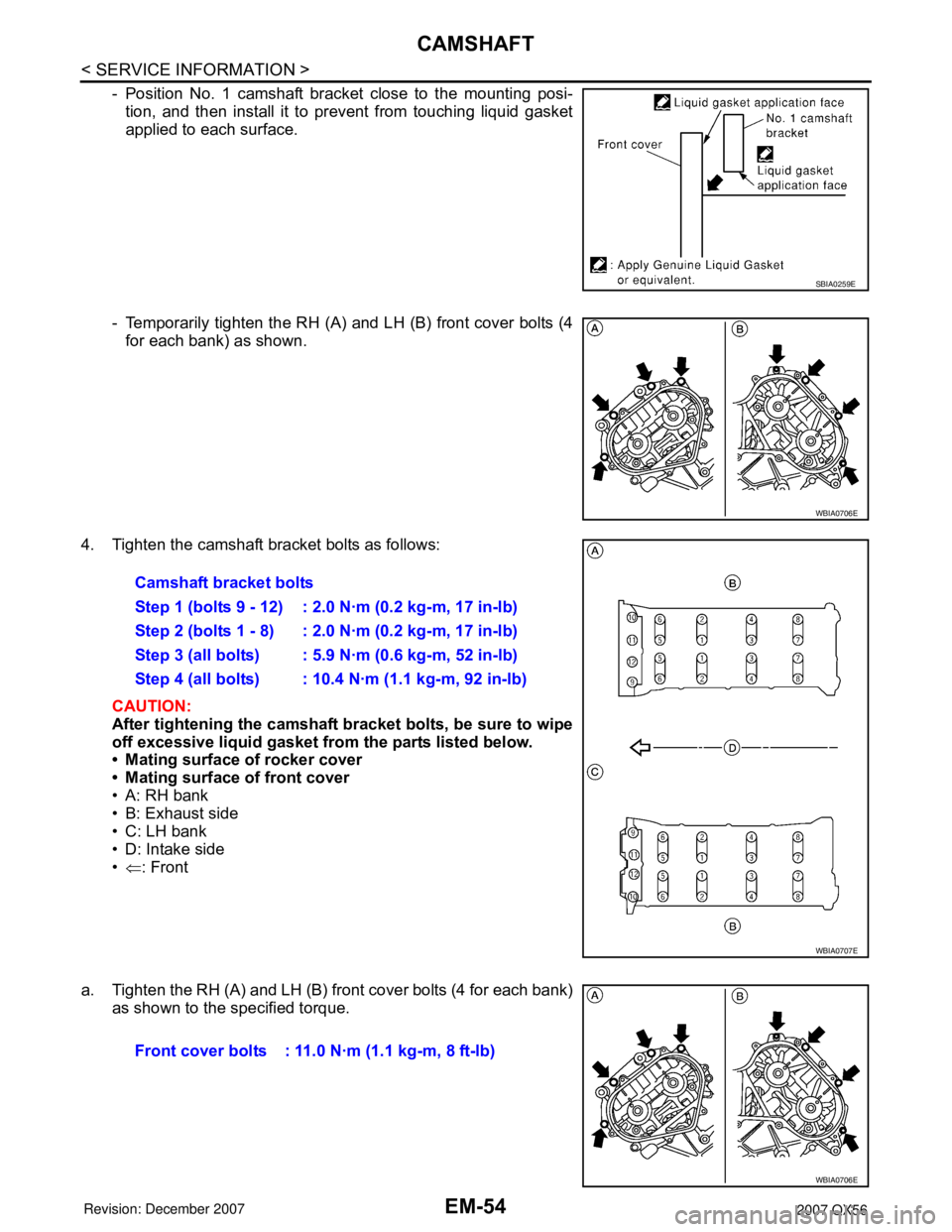
- Position No. 1 camshaft bracket close to the mounting posi-
tion, and then install it to prevent from touching liquid gasket
applied to each surface.
- Temporarily tighten the RH (A) and LH (B) front cover bolts (4 for each bank) as shown.
4. Tighten the camshaft bracket bolts as follows: CAUTION:
After tightening the camshaft br acket bolts, be sure to wipe
off excessive liquid gasket from the parts listed below.
• Mating surface of rocker cover
• Mating surface of front cover
• A: RH bank
• B: Exhaust side
• C: LH bank
• D: Intake side
• ⇐ : Front
a. Tighten the RH (A) and LH (B) front cover bolts (4 for each bank) as shown to the specified torque.
SBIA0259E
WBIA0706E
Camshaft bracket bolts
Step 1 (bolts 9 - 12) : 2.0 N·m (0.2 kg-m, 17 in-lb)
Step 2 (bolts 1 - 8) : 2.0 N·m (0.2 kg-m, 17 in-lb)
Step 3 (all bolts) : 5.9 N·m (0.6 kg-m, 52 in-lb)
Step 4 (all bolts) : 10.4 N·m (1.1 kg-m, 92 in-lb)
WBIA0707E
Front cover bolts : 11.0 N·m (1.1 kg-m, 8 ft-lb)
WBIA0706E