torque INFINITI QX56 2007 Factory Workshop Manual
[x] Cancel search | Manufacturer: INFINITI, Model Year: 2007, Model line: QX56, Model: INFINITI QX56 2007Pages: 3061, PDF Size: 64.56 MB
Page 359 of 3061
ASSEMBLY
AT-289
< SERVICE INFORMATION >
D
E
F
G
H
I
J
K
L
MA
B
AT
N
O
P
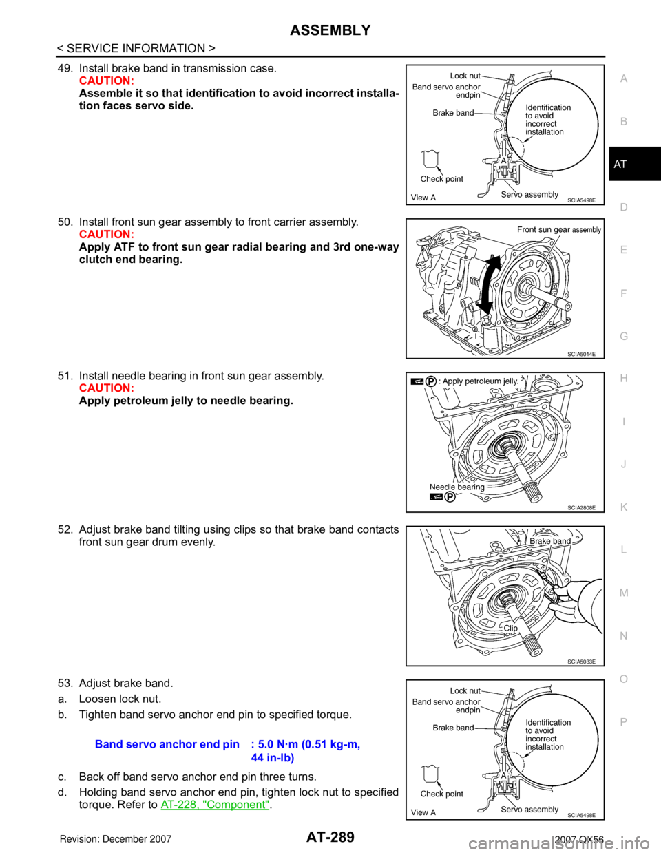
49. Install brake band in transmission case.
CAUTION:
Assemble it so that identification to avoid incorrect installa-
tion faces servo side.
50. Install front sun gear assembly to front carrier assembly.
CAUTION:
Apply ATF to front sun gear radial bearing and 3rd one-way
clutch end bearing.
51. Install needle bearing in front sun gear assembly.
CAUTION:
Apply petroleum jelly to needle bearing.
52. Adjust brake band tilting using clips so that brake band contacts
front sun gear drum evenly.
53. Adjust brake band.
a. Loosen lock nut.
b. Tighten band servo anchor end pin to specified torque.
c. Back off band servo anchor end pin three turns.
d. Holding band servo anchor end pin, tighten lock nut to specified
torque. Refer to AT-228, "
Component".
SCIA5498E
SCIA5014E
SCIA2808E
SCIA5033E
Band servo anchor end pin : 5.0 N·m (0.51 kg-m,
44 in-lb)
SCIA5498E
Page 363 of 3061
ASSEMBLY
AT-293
< SERVICE INFORMATION >
D
E
F
G
H
I
J
K
L
MA
B
AT
N
O
P
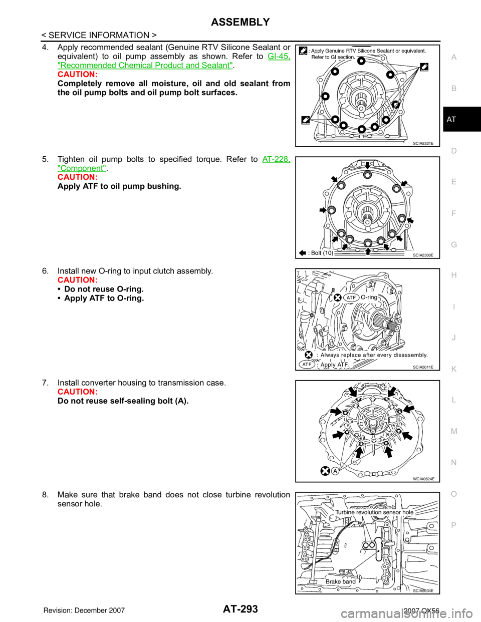
4. Apply recommended sealant (Genuine RTV Silicone Sealant or
equivalent) to oil pump assembly as shown. Refer to GI-45,
"Recommended Chemical Product and Sealant".
CAUTION:
Completely remove all moisture, oil and old sealant from
the oil pump bolts and oil pump bolt surfaces.
5. Tighten oil pump bolts to specified torque. Refer to AT-228,
"Component".
CAUTION:
Apply ATF to oil pump bushing.
6. Install new O-ring to input clutch assembly.
CAUTION:
• Do not reuse O-ring.
• Apply ATF to O-ring.
7. Install converter housing to transmission case.
CAUTION:
Do not reuse self-sealing bolt (A).
8. Make sure that brake band does not close turbine revolution
sensor hole.
SCIA5321E
SCIA2300E
SCIA5011E
WCIA0624E
SCIA5034E
Page 364 of 3061
AT-294
< SERVICE INFORMATION >
ASSEMBLY
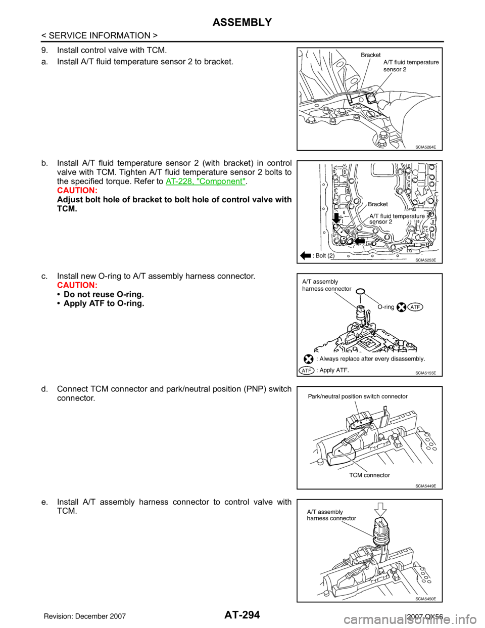
9. Install control valve with TCM.
a. Install A/T fluid temperature sensor 2 to bracket.
b. Install A/T fluid temperature sensor 2 (with bracket) in control
valve with TCM. Tighten A/T fluid temperature sensor 2 bolts to
the specified torque. Refer to AT-228, "
Component".
CAUTION:
Adjust bolt hole of bracket to bolt hole of control valve with
TCM.
c. Install new O-ring to A/T assembly harness connector.
CAUTION:
• Do not reuse O-ring.
• Apply ATF to O-ring.
d. Connect TCM connector and park/neutral position (PNP) switch
connector.
e. Install A/T assembly harness connector to control valve with
TCM.
SCIA5264E
SCIA5253E
SCIA5155E
SCIA5449E
SCIA5450E
Page 365 of 3061
ASSEMBLY
AT-295
< SERVICE INFORMATION >
D
E
F
G
H
I
J
K
L
MA
B
AT
N
O
P
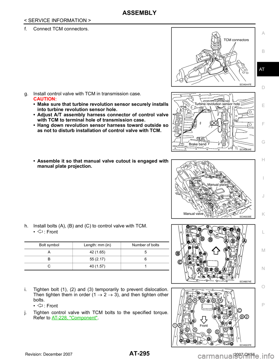
f. Connect TCM connectors.
g. Install control valve with TCM in transmission case.
CAUTION:
• Make sure that turbine revolution sensor securely installs
into turbine revolution sensor hole.
• Adjust A/T assembly harness connector of control valve
with TCM to terminal hole of transmission case.
• Hang down revolution sensor harness toward outside so
as not to disturb installation of control valve with TCM.
• Assemble it so that manual valve cutout is engaged with
manual plate projection.
h. Install bolts (A), (B) and (C) to control valve with TCM.
• : Front
i. Tighten bolt (1), (2) and (3) temporarily to prevent dislocation.
Then tighten them in order (1 → 2 → 3), and then tighten other
bolts.
• : Front
j. Tighten control valve with TCM bolts to the specified torque.
Refer to AT-228, "
Component".
SCIA5447E
SCIA5034E
SCIA5035E
Bolt symbol Length: mm (in) Number of bolts
A 42 (1.65) 5
B 55 (2.17) 6
C 40 (1.57) 1
SCIA8074E
SCIA5037E
Page 367 of 3061
ASSEMBLY
AT-297
< SERVICE INFORMATION >
D
E
F
G
H
I
J
K
L
MA
B
AT
N
O
P
17. Install the oil pan and new oil pan gasket. Refer to AT-209, "Oil Pan".
CAUTION:
• Do not reuse the oil pan gasket.
• Completely remove all moisture, oil and old gasket from the oil pan gasket mating surfaces and
holes.
• Always replace the oil pan bolts as they are self-sealing.
• Be sure the oil pan drain plug hole is located to the rear of the transmission assembly.
• Partially install the oil pan bolts in a criss-cross pattern to prevent dislocation of the gasket.
• Be careful not to pinch harnesses.
18. Install drain plug in oil pan with new gasket.
CAUTION:
Do not reuse the drain plug gasket.
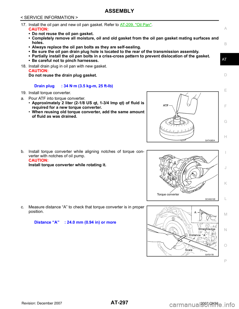
19. Install torque converter.
a. Pour ATF into torque converter.
•Approximately 2 liter (2-1/8 US qt, 1-3/4 Imp qt) of fluid is
required for a new torque converter.
•When reusing old torque converter, add the same amount
of fluid as was drained.
b. Install torque converter while aligning notches of torque con-
verter with notches of oil pump.
CAUTION:
Install torque converter while rotating it.
c. Measure distance “A” to check that torque converter is in proper
position.Drain plug : 34 N·m (3.5 kg-m, 25 ft-lb)
SAT428DA
SCIA5010E
Distance “A” : 24.0 mm (0.94 in) or more
SAT017B
Page 368 of 3061
AT-298
< SERVICE INFORMATION >
SERVICE DATA AND SPECIFICATIONS (SDS)
SERVICE DATA AND SPECIFICATIONS (SDS)
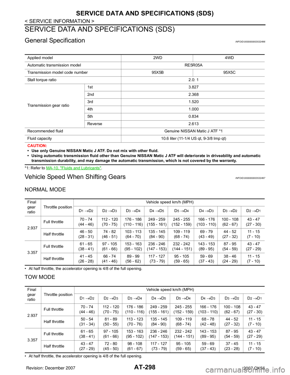
General SpecificationINFOID:0000000003532496
*1: Refer to MA-10, "Fluids and Lubricants".
Vehicle Speed When Shifting GearsINFOID:0000000003532497
NORMAL MODE
• At half throttle, the accelerator opening is 4/8 of the full opening.
TOW MODE
• At half throttle, the accelerator opening is 4/8 of the full opening.Applied model 2WD 4WD
Automatic transmission model RE5R05A
Transmission model code number 95X5B 95X5C
Stall torque ratio2.0: 1
Transmission gear ratio1st 3.827
2nd 2.368
3rd 1.520
4th 1.000
5th 0.834
Reverse 2.613
Recommended fluid Genuine NISSAN Matic J ATF *1
Fluid capacity 10.6 liter (11-1/4 US qt, 9-3/8 Imp qt)
CAUTION:
• Use only Genuine NISSAN Matic J ATF. Do not mix with other fluid.
• Using automatic transmission fluid other than Genuine NISSAN Matic J ATF will deteriorate in driveability and automatic
transmission durability, and may damage the automatic transmission, which is not covered by the warranty.
Final
gear
ratioThrottle positionVehicle speed km/h (MPH)
D
1 →D2D2 →D3D3 →D4D4 →D5D5 →D4D4 →D3D3 →D2D2 →D1
2.937Full throttle 70 - 74
(44 - 46)112 - 120
(70 - 75)176 - 186
(110 - 116)249 - 259
(155 - 161)245 - 255
(152 - 159)166 - 176
(103 - 110)100 - 108
(62 - 67)43 - 47
(27 - 30)
Half throttle 46 - 50
(28 - 31)74 - 82
(46 - 51)103 - 113
(64 - 70)135 - 145
(84 - 90)109 - 119
(68 - 74)69 - 79
(43 - 49)44 - 52
(27 - 32)11 - 1 5
(7 - 10)
3.357Full throttle 61 - 65
(38 - 41)97 - 105
(61 - 66)153 - 163
(95 - 102)236 - 246
(147 - 153)232 - 242
(144 - 151)143 - 153
(89 - 95)87 - 95
(54 - 59)43 - 47
(27 - 29)
Half throttle 41 - 45
(26 - 28)66 - 74
(41 - 46)89 - 99
(56 - 62)117 - 127
(73 - 79)95 - 105
(59 - 65)59 - 69
(37 - 43)38 - 46
(24 - 29)11 - 1 5
(7 - 10)
Final
gear
ratioThrottle positionVehicle speed km/h (MPH)
D
1 →D2D2 →D3D3 →D4D4 →D5D5 →D4D4 →D3D3 →D2D2 →D1
2.937Full throttle 70 - 74
(44 - 46)112 - 120
(70 - 75)176 - 186
(110 - 116)249 - 259
(155 - 161)245 - 255
(152 - 159)166 - 176
(103 - 110)100 - 108
(62 - 67)43 - 47
(27 - 30)
Half throttle 50 - 54
(31 - 34)81 - 89
(50 - 55)113 - 123
(70 - 76)135 - 145
(84 - 90)109 - 119
(68 - 74)68 - 78
(42 - 48)44 - 52
(27 - 32)11 - 1 5
(7 - 10)
3.357Full throttle 61 - 65
(38 - 41)97 - 105
(61 - 66)153 - 163
(95 - 102)236 - 246
(147 - 153)232 - 242
(144 - 151)143 - 153
(89 - 95)87 - 95
(54 - 59)43 - 47
(27 - 29)
Half throttle 43 - 47
(27 - 29)72 - 80
(45 - 50)98 - 108
(61 - 67)117 - 127
(73 - 79)95 - 105
(59 - 65)59 - 69
(37 - 43)37 - 45
(23 - 28)11 - 1 5
(7 - 10)
Page 377 of 3061
PRECAUTIONSATC-7
< SERVICE INFORMATION >
C
DE
F
G H
I
K L
M A
B
AT C
N
O P
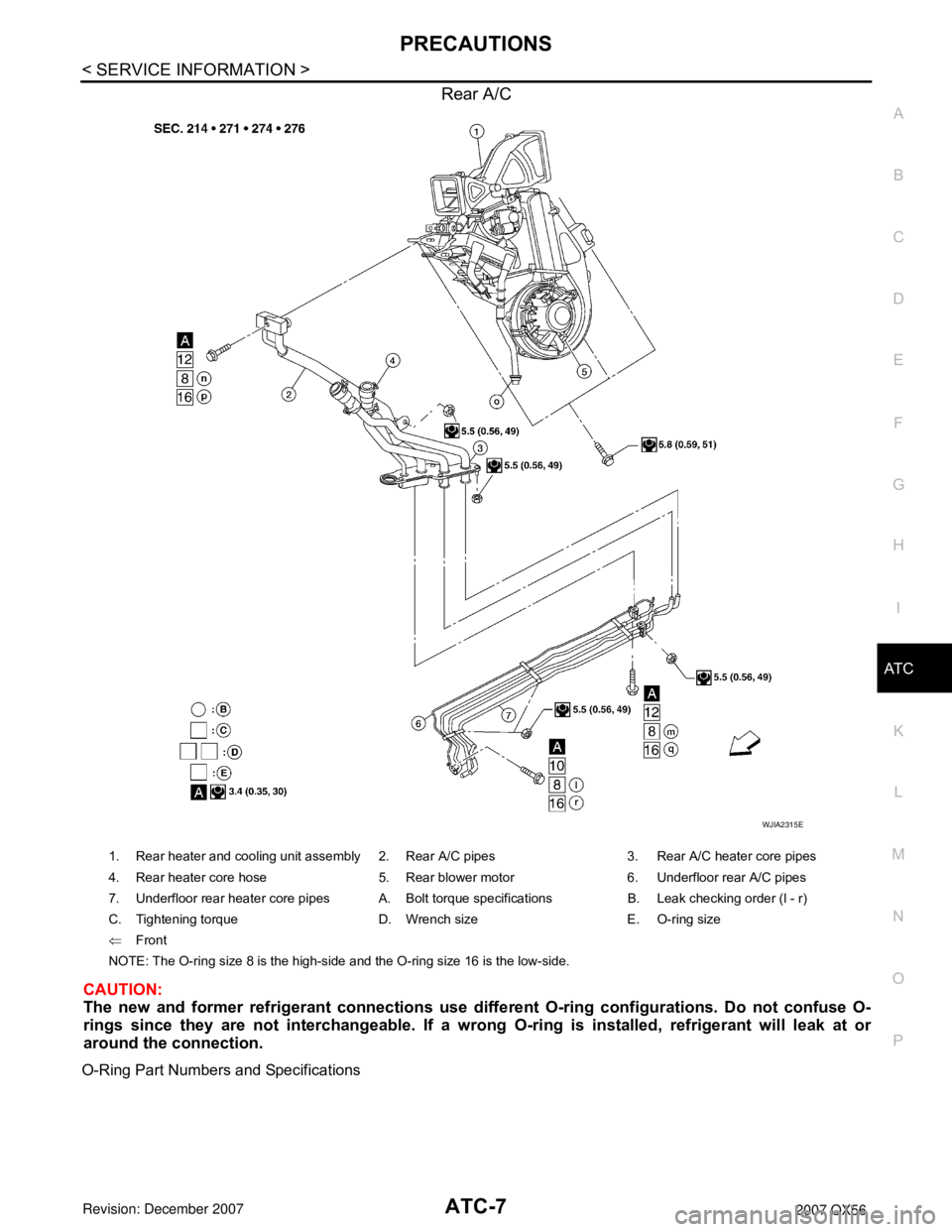
Rear A/C
CAUTION:
The new and former refrigerant connections use diffe rent O-ring configurations. Do not confuse O-
rings since they are not interchangeable. If a wrong O-ring is installed, refrigerant will leak at or
around the connection.
O-Ring Part Numbers and Specifications
WJIA2315E
1. Rear heater and cooling unit assembly 2. Rear A/C pipes 3. Rear A/C heater core pipes
4. Rear heater core hose 5. Rear blower motor 6. Underfloor rear A/C pipes
7. Underfloor rear heater core pipes A. Bolt torque specifications B. Leak checking order (l - r)
C. Tightening torque D. Wrench size E. O-ring size
⇐ Front
NOTE: The O-ring size 8 is the high-side and the O-ring size 16 is the low-side.
Page 378 of 3061
ATC-8
< SERVICE INFORMATION >
PRECAUTIONS
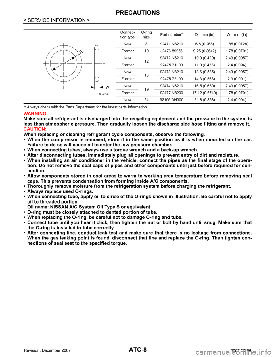
*: Always check with the Parts Department for the latest parts information.
WARNING:
Make sure all refrigerant is discharged into the recycling equipment and the pressure in the system is
less than atmospheric pressure. Then gradually loo sen the discharge side hose fitting and remove it.
CAUTION:
When replacing or cleaning refrigeran t cycle components, observe the following.
• When the compressor is removed, store it in the same position as it is when mounted on the car.
Failure to do so will cause oil to enter the low pressure chamber.
• When connecting tubes, always use a torque wrench and a back-up wrench.
• After disconnecting tubes, immedi ately plug all openings to prevent entry of dirt and moisture.
• When installing an air conditioner in the vehicle, connect the pipes as the final stage of the opera-
tion. Do not remove the seal caps of pipes and othe r components until just before required for con-
nection.
• Allow components stored in cool areas to warm to working area temperature before removing seal
caps. This prevents condensation from forming inside A/C components.
• Thoroughly remove moisture from the refrigerat ion system before charging the refrigerant.
• Always replace used O-rings.
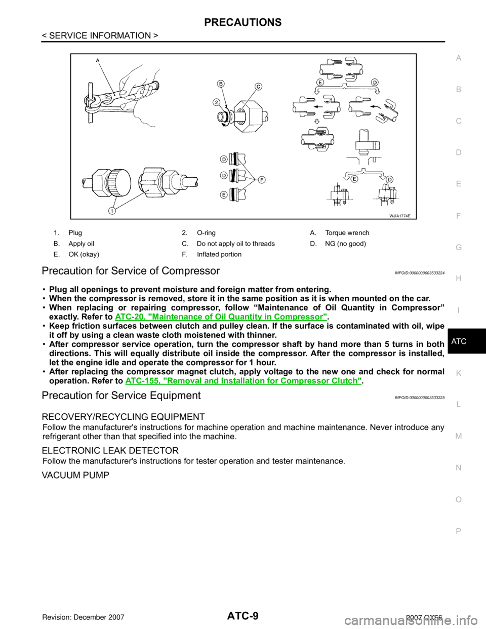
• When connecting tube, apply oil to circle of the O-rings shown in illustration. Be careful not to apply
oil to threaded portion.
Oil name: NISSAN A/C System Oil Type S or equivalent
• O-ring must be closely attached to dented portion of tube.
• When replacing the O-ring, be careful not to damage O-ring and tube.
• Connect tube until you hear it cl ick, then tighten the nut or bolt by hand until snug. Make sure that
the O-ring is installed to tube correctly.
• After connecting line, conduct leak test and make sure that there is no leakage from connections.
When the gas leaking point is foun d, disconnect that line and replace the O-ring. Then tighten con-
nections of seal seat to the specified torque.
Connec-
tion typeO-ring
size Part number* D mm (in) W mm (in)
New 8 92471 N8210 6.8 (0.268) 1.85 (0.0728)
Former 10 J2476 89956 9.25 (0.3642) 1.78 (0.0701) New 1292472 N8210 10.9 (0.429) 2.43 (0.0957)
Former 92475 71L00 11.0 (0.433) 2.4 (0.094) New 1692473 N8210 13.6 (0.535) 2.43 (0.0957)
Former 92475 72L00 14.3 (0.563) 2.3 (0.091) New 1992474 N8210 16.5 (0.650) 2.43 (0.0957)
Former 92477 N8200 17.12 (0.6740) 1.78 (0.0701) New 24 92195 AH300 21.8 (0.858) 2.4 (0.094)
SHA814E
Page 379 of 3061
PRECAUTIONSATC-9
< SERVICE INFORMATION >
C
DE
F
G H
I
K L
M A
B
AT C
N
O P
Precaution for Service of CompressorINFOID:0000000003533224
• Plug all openings to prevent moisture and foreign matter from entering.
• When the compressor is removed, store it in the same position as it is when mounted on the car.
• When replacing or repairing co mpressor, follow “Maintenance of Oil Quantity in Compressor”
exactly. Refer to ATC-20, "
Maintenance of Oil Quantity in Compressor".
• Keep friction surfaces between clutch and pulley clean . If the surface is contaminated with oil, wipe
it off by using a clean wast e cloth moistened with thinner.
• After compressor service operation, turn the compressor shaft by hand more than 5 turns in both
directions. This will equa lly distribute oil inside the compresso r. After the compressor is installed,
let the engine idle and oper ate the compressor for 1 hour.
• After replacing the compressor magnet clutch, ap ply voltage to the new one and check for normal
operation. Refer to ATC-155, "
Removal and Installation for Compressor Clutch".
Precaution for Service EquipmentINFOID:0000000003533225
RECOVERY/RECYCLING EQUIPMENT
Follow the manufacturer's instructions for machine operation and machine maintenance. Never introduce any
refrigerant other than that specified into the machine.
ELECTRONIC LEAK DETECTOR
Follow the manufacturer's instructions fo r tester operation and tester maintenance.
VACUUM PUMP
1. Plug 2. O-ring A. Torque wrench
B. Apply oil C. Do not apply oil to threads D. NG (no good)
E. OK (okay) F. Inflated portion
WJIA1774E
Page 503 of 3061
HEATER & COOLING UNIT ASSEMBLYATC-133
< SERVICE INFORMATION >
C
DE
F
G H
I
K L
M A
B
AT C
N
O P
Rear Heater and Cooling Unit Assembly
Removal and InstallationINFOID:0000000003533279
FRONT HEATER AND COOLING UNIT ASSEMBLY
Removal
1. Move the two front seats to the rearmost position on the seat track.
2. Disconnect the battery negative terminal and battery positive terminal.
3. Discharge the refrigerant from the A/C system. Refer to ATC-150, "
HFC-134a (R-134a) Service Proce-
dure".
4. Drain the coolant from the engine cooling system. Refer to MA-12, "
Changing Engine Coolant".
WJIA2315E
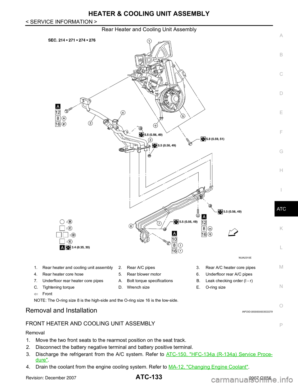
1. Rear heater and cooling unit assembly 2. Rear A/C pipes 3. Rear A/C heater core pipes
4. Rear heater core hose 5. Rear blower motor 6. Underfloor rear A/C pipes
7. Underfloor rear heater core pipes A. Bolt torque specifications B. Leak checking order (l - r)
C. Tightening torque D. Wrench size E. O-ring size
⇐Front
NOTE: The O-ring size 8 is the high-side and the O-ring size 16 is the low-side.