body int INFINITI QX56 2011 Factory Owner's Manual
[x] Cancel search | Manufacturer: INFINITI, Model Year: 2011, Model line: QX56, Model: INFINITI QX56 2011Pages: 5598, PDF Size: 94.53 MB
Page 699 of 5598

BRM-24
< REMOVAL AND INSTALLATION >
REPLACEMENT OPERATIONS
REPLACEMENT OPERATIONS
DescriptionINFOID:0000000006248496
This section is prepared for technicians who have attained a high level of skill and experience in repairingcollision-damaged vehicles and also use modern serv ice tools and equipment. Persons unfamiliar with body
repair techniques should not attempt to repair collision-damaged vehicles by using this section.
Technicians are also encouraged to read the Body Repair Manual (Fundamentals) in order to ensure that the
original functions and quality of the vehicle are ma intained. The Body Repair Manual (Fundamentals) con-
tains additional information, including cautions and warnings, that are not including in this manual. Techni-
cians should refer to both manuals to ensure proper repair.
Please note that this information is prepared for worldwide usage, and as such, certain procedures might not apply in some regions or countries.
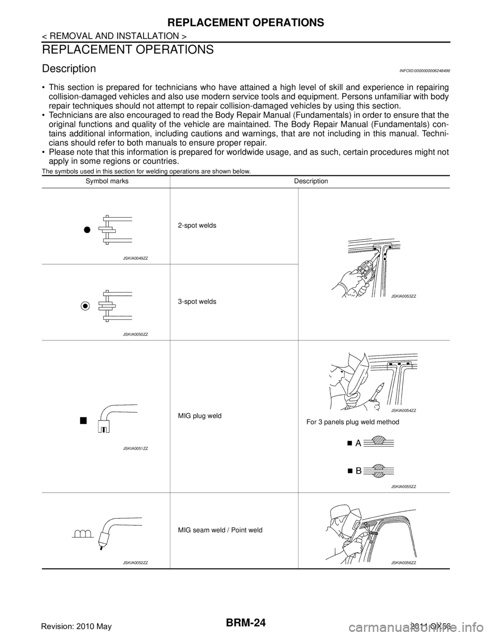
The symbols used in this section fo r welding operations are shown below.
Symbol marks Description
2-spot welds
3-spot welds
MIG plug weld For 3 panels plug weld method
MIG seam weld / Point weld
JSKIA0049ZZ
JSKIA0053ZZ
JSKIA0050ZZ
JSKIA0051ZZ
JSKIA0054ZZ
JSKIA0055ZZ
JSKIA0052ZZJSKIA0056ZZ
Revision: 2010 May2011 QX56
Page 723 of 5598

BRM-48
< SERVICE DATA AND SPECIFICATIONS (SDS)
BODY ALIGNMENT
SERVICE DATA AND SPECIFICATIONS (SDS)
BODY ALIGNMENT
Body Center MarksINFOID:0000000006248507
A mark is placed on each part of the body to indicate the vehicle center. When repairing the vehicle frame
(members, pillars, etc.) damaged by an accident which it enables more accurate and effective repair by using
these marks together with body alignment specifications.
Unit: mm (in)
DescriptionINFOID:0000000006248508
All dimensions indicated in the figures are actual.
When using a tracking gauge, adjust both pointers to equal length. Then check the pointers and gauge itself
to make sure there is no free play.
: Vehicle front
Points Portion Marks
A Upper dash Hole 7 ×12 (0.28 ×0.47)
B Cowl top Embossment
C Rear roof Indent
JSKIA1895ZZ
Revision: 2010 May2011 QX56
Page 724 of 5598

BODY ALIGNMENTBRM-49
< SERVICE DATA AND SPECIFICATIONS (SDS)
C
DE
F
G H
I
J
L
M A
B
BRM
N
O P
When a measuring tape is used, check to be su re there is no elongation, twisting or bending.
Measurements should be taken at the center of the mounting holes.
An asterisk (*) following the value at the measuring poi nt indicates that the measuring point on the other side
is symmetrically the same value.
The coordinates of the measurement points are the distances measured from the standard line of ″X ″, ″Y ″
and ″Z ″.
″Z ″: Imaginary base line [300 mm (11.81 in) below datum line ( ″0Z ″ at design plan)]
Engine CompartmentINFOID:0000000006248509
Measurement
Dimensions marked with ″*″ indicate symmetrically identical dimensions on both the right and left hand of the
vehicle.
1. Vehicle center 2. Front axle center 3. Imaginary base line
JSKIA0073GB
Revision: 2010 May2011 QX56
Page 725 of 5598

BRM-50
< SERVICE DATA AND SPECIFICATIONS (SDS)
BODY ALIGNMENT
«The others»Unit: mm (in)
Measurement Points
Unit: mm (in)
Point Dimension Memo Point Dimension Memo Point Dimension Memo Point Dimension Memo
A - C 865 (34.06)* C - M 897 (35.31)* F - m 1467 (57.76)* N - o 1078 (42.44)*
A - D 871 (34.29)* C - m 1635 (64.37)* G - g 1608 (63.31) N - p 1117 (43.98)* A - F 821 (32.32)* D - d 1719 (67.68) G - j 1614 (63.54)* N - Q 397 (15.63)*
A - H 938 (36.93)* E - M 625 (24.61)* G - M 613 (24.13)* O - o 1077 (42.40)
A - K 1013 (39.88)* E - m 1320 (51.97)* G - m 1457 (57.36)* O - P 322 (12.68)*
B - G 453 (17.83)* F - f 1588 (62.52) H - h 1657 (65.24) O - p 1108 (43.62)* B - g 1740 (68.50)* F - J 257 (10.12)* J - M 427 (16.81)* O - q 1123 (44.21)*
B - j 1798 (70.79)* F - j 1611 (63.43)* J - m 1383 (54.45)* P - p 1044 (41.10)
C - c 1720 (67.72) F - M 652 (25.67)* K - k 1600 (62.99) P - q 1045 (41.14)*
JSKIA1946GB
Revision: 2010 May2011 QX56
Page 726 of 5598

BODY ALIGNMENTBRM-51
< SERVICE DATA AND SPECIFICATIONS (SDS)
C
DE
F
G H
I
J
L
M A
B
BRM
N
O P
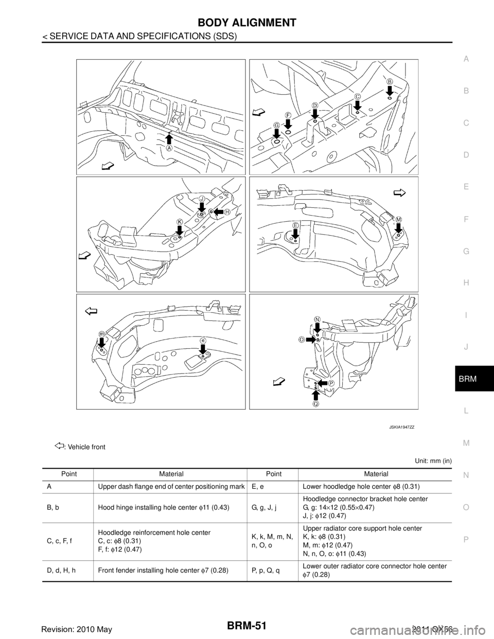
Unit: mm (in)
: Vehicle front
JSKIA1947ZZ
Point Material Point Material
A Upper dash flange end of center positioning mark E, e Lower hoodledge hole center φ8 (0.31)
B, b Hood hinge installing hole center φ11 (0.43) G, g, J, j Hoodledge connector bracket hole center
G, g: 14
×12 (0.55 ×0.47)
J, j: φ12 (0.47)
C, c, F, f Hoodledge reinforcement hole center
C, c:
φ8 (0.31)
F, f: φ12 (0.47) K, k, M, m, N,
n, O, oUpper radiator core support hole center
K, k:
φ8 (0.31)
M, m: φ12 (0.47)
N, n, O, o: φ11 ( 0 . 4 3 )
D, d, H, h Front fender installing hole center φ7 (0.28) P, p, Q, q Lower outer radiator core connector hole center
φ
7 (0.28)
Revision: 2010 May2011 QX56
Page 728 of 5598

BODY ALIGNMENTBRM-53
< SERVICE DATA AND SPECIFICATIONS (SDS)
C
DE
F
G H
I
J
L
M A
B
BRM
N
O P
Measurement Points
Unit: mm (in)
Unit: mm (in) : Vehicle front
: Vehicle left side
: Vehicle front
Points Coordinates
Remarks Points Coordinates
Remarks
XYZ XYZ
A, a ±
439.0
( ± 17.283) −
583.9
( − 22.988) 220.3
(8.673) Hole
φ16 (0.63) F, f ±
555.0
( ± 21.850) 2645.0
(104.134) 195.0
(7.677) Hole
φ19.5 (0.768)
B, b ±
460.0
( ± 18.110) −
260.0
( − 10.236) 199.9
(7.870) Hole
φ12 (0.47) G, g ±
564.0
( ± 22.205) 3110.0
(122.441) 400.0
(15.748) Hole
φ16 (0.63)
C 274.6
(10.811) −
11 . 1
( − 0.437) 329.2
(12.961) Hole
φ19 (0.75) H, h ±
559.0
( ± 22.008) 3335.0
(131.299) 400.0
(15.748) Hole
φ16 (0.63)
JSKIA1949ZZ
Revision: 2010 May2011 QX56
Page 729 of 5598

BRM-54
< SERVICE DATA AND SPECIFICATIONS (SDS)
BODY ALIGNMENT
Passenger Compartment
INFOID:0000000006248511
Measurement
Dimensions marked with ″*″ indicate symmetrically identical dimensions on both the right and left hand of the
vehicle.
«The others»
c −
289.6
( − 11 . 4 0 2 ) 0.2
(0.008) 305.8
(12.039) Hole
φ19 (0.75) J, j ±
501.7
( ± 19.752) 3750.7
(147.665) 378.4
(14.898) Hole
φ8 (0.31)
D, d ±
461.8
( ± 18.181) 807.5
(31.791) 104.1
(4.098) Hole
φ10 (0.39) K, k ±
561.6
( ± 22.110) 4050.0
(159.449) 337.0
(13.268) Hole
φ15 (0.59)
E, e ±
592.0
( ± 23.307) 1320.0
(51.968) 98.3
(3.870) Hole 20
×8
(0.79 ×0.31) M, m
±
498.4
( ± 19.622) -29.6
(-1.165) 519.2
(20.441) Hole
φ70 (2.76)
Points
Coordinates
Remarks Points Coordinates
Remarks
XYZ XYZ
Unit: mm (in)
JSKIA1900GB
Revision: 2010 May2011 QX56
Page 730 of 5598

BODY ALIGNMENTBRM-55
< SERVICE DATA AND SPECIFICATIONS (SDS)
C
DE
F
G H
I
J
L
M A
B
BRM
N
O P
Unit: mm (in)
Measurement Points
Point Dimension Memo Point Dimension Memo Point Dimension Memo Point Dimension Memo E - e 1442 (56.77) G - j 1863 (73.35)* M - o 1995 (78.54)* Q - H 1217 (47.91)* E - f 1638 (64.49)* H - h 1528 (60.16)* M - p 1760 (69.29)* Q - J 823 (32.40)*
E - g 1987 (78.23)* H - j 1776 (69.92)* N - n 1416 (55.75) R - K 1133 (44.61)*
E - h 1526 (60.08)* J - j 1651 (65.00) N - o 1475 (58.07)* R - M 820 (32.28)*
E - j 1792 (70.55)* K - k 1527 (60.12) N - p 1839 (72.40)* R - N 1182 (46.54)*
F - f 1615 (63.58) K - m 1799 (70.83)* O - o 1480 (58.27) R - O 1198 (47.17)*
F - g 1802 (70.94)* K - n 1582 (62.28)* O - p 1829 (72.01)* R - P 760 (29.92)*
F - h 1792 (70.55)* K - o 1716 (67.56)* P - p 1641 (64.61) S - U 1183 (46.57)*
F - j 1864 (73.39)* K - p 1906 (75.04)* Q - E 1178 (46.38)* S - V 1195 (47.05)*
G - g 1644 (64.72) M - m 1648 (64.88) Q - F 1031 (40.59)* T - U 1293 (50.91)*
G - h 2104 (82.83)* M - n 1919 (75.55)* Q - G 876 (34.49)* T - V 1158 (45.59)*
JSKIA1901ZZ
Revision: 2010 May2011 QX56
Page 731 of 5598

BRM-56
< SERVICE DATA AND SPECIFICATIONS (SDS)
BODY ALIGNMENT
Unit: mm (in)
Rear BodyINFOID:0000000006248512
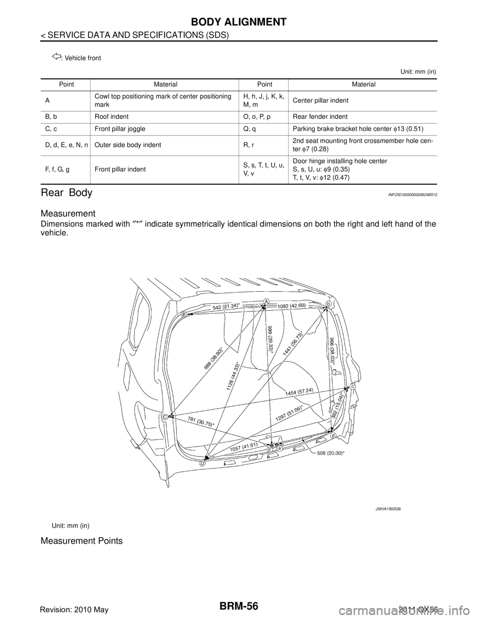
Measurement
Dimensions marked with ″*″ indicate symmetrically identical dimensions on both the right and left hand of the
vehicle.
Measurement Points
: Vehicle front
Point Material Point Material
A Cowl top positioning mark of center positioning
mark H, h, J, j, K, k,
M, m
Center pillar indent
B, b Roof indent O, o, P, p Rear fender indent
C, c Front pillar joggle Q, q Parking brake bracket hole center φ13 (0.51)
D, d, E, e, N, n Outer side body indent R, r 2nd seat mounting front crossmember hole cen-
ter
φ7 (0.28)
F, f, G, g Front pillar indent S, s, T, t, U, u,
V, vDoor hinge installing hole center
S, s, U, u:
φ9 (0.35)
T, t, V, v: φ12 (0.47)
Unit: mm (in)
JSKIA1902GB
Revision: 2010 May2011 QX56
Page 732 of 5598

BODY ALIGNMENTBRM-57
< SERVICE DATA AND SPECIFICATIONS (SDS)
C
DE
F
G H
I
J
L
M A
B
BRM
N
O P
Unit: mm (in)
: Vehicle front
Point Material Point Material
A Roof indent of center positioning mark D, d Rear center crossmember joggle
B, b Upper back pillar main joggle E, e Rear end crossmember hole center φ13 (0.51)
C, c Upper back pillar main hole center φ7 (0.28)
JSKIA1903ZZ
Revision: 2010 May2011 QX56