body int INFINITI QX56 2011 Factory User Guide
[x] Cancel search | Manufacturer: INFINITI, Model Year: 2011, Model line: QX56, Model: INFINITI QX56 2011Pages: 5598, PDF Size: 94.53 MB
Page 515 of 5598
REAR DISC BRAKEBR-45
< REMOVAL AND INSTALLATION >
C
DE
G H
I
J
K L
M A
B
BR
N
O P
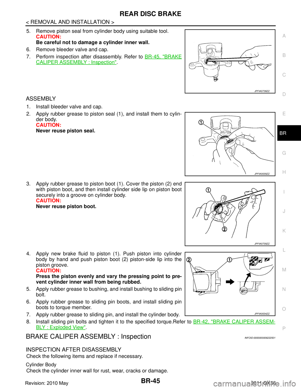
5. Remove piston seal from cylinder body using suitable tool. CAUTION:
Be careful not to damage a cylinder inner wall.
6. Remove bleeder valve and cap.
7. Perform inspection after disassembly. Refer to BR-45, "
BRAKE
CALIPER ASSEMBLY : Inspection".
ASSEMBLY
1. Install bleeder valve and cap.
2. Apply rubber grease to piston seal (1), and install them to cylin-
der body.
CAUTION:
Never reuse piston seal.
3. Apply rubber grease to piston boot (1). Cover the piston (2) end with piston boot, and then install cylinder side lip on piston boot
securely into a groove on cylinder body.
CAUTION:
Never reuse piston boot.
4. Apply new brake fluid to piston (1). Push piston into cylinder body by hand and push piston boot (2) piston-side lip into the
piston groove.
CAUTION:
Press the piston evenly and var y the pressing point to pre-
vent cylinder inner wall from being rubbed.
5. Apply rubber grease to bushing, and install bushing to sliding pin bolt.
6. Apply rubber grease to sliding pin boots, and install sliding pin boots to torque member.
7. Apply rubber grease to sliding pin, and install the cylinder body.
8. Install sliding pin bolts and tighten it to the specified torque.Refer to BR-42, "
BRAKE CALIPER ASSEM-
BLY : Exploded View".
BRAKE CALIPER ASSEMBLY : InspectionINFOID:0000000006222501
INSPECTION AFTER DISASSEMBLY
Check the following items and replace if necessary.
Cylinder Body
Check the cylinder inner wall for rust, wear, cracks or damage.
JPFIA0738ZZ
JPFIA0039ZZ
JPFIA0739ZZ
JPFIA0034ZZ
Revision: 2010 May2011 QX56
Page 666 of 5598
![INFINITI QX56 2011 Factory User Guide
COMPONENT PARTSBRC-149
< SYSTEM DESCRIPTION > [INTELLIGENT BRAKE ASSIST]
C
D
E
G H
I
J
K L
M A
B
BRC
N
O P
SYSTEM DESCRIPTION
COMPONENT PARTS
Component Parts LocationINFOID:0000000006248458
1. ICC st INFINITI QX56 2011 Factory User Guide
COMPONENT PARTSBRC-149
< SYSTEM DESCRIPTION > [INTELLIGENT BRAKE ASSIST]
C
D
E
G H
I
J
K L
M A
B
BRC
N
O P
SYSTEM DESCRIPTION
COMPONENT PARTS
Component Parts LocationINFOID:0000000006248458
1. ICC st](/img/42/57033/w960_57033-665.png)
COMPONENT PARTSBRC-149
< SYSTEM DESCRIPTION > [INTELLIGENT BRAKE ASSIST]
C
D
E
G H
I
J
K L
M A
B
BRC
N
O P
SYSTEM DESCRIPTION
COMPONENT PARTS
Component Parts LocationINFOID:0000000006248458
1. ICC steering switch 2. Information display, ICC system warning lamp, IBA OFF indicator
lamp, buzzer
(On the combination meter)3. BCM
Refer to BCS-4, "
BODY CONTROL
SYSTEM : Compon ent Parts Loca-
tion"
4. Transfer control unit
Refer to DLN-10, "
Component Parts
Location"
5. ICC brake hold relay 6. ECM
Refer to EC-16, "
Component Parts
Location"
7. ICC sensor 8. TCM
Refer to TM-10, "
A/T CONTROL
SYSTEM : Compon ent Parts Loca-
tion"
9. ABS actuator and electric unit (con-
trol unit)
Refer to BRC-10, "
Component Parts
Location"
10. Stop lamp switch 11. ICC brake switch 12. IBA OFF switch
JSOIA0362ZZ
Revision: 2010 May2011 QX56
Page 676 of 5598

BRM-1
BODY EXTERIOR, DOORS, ROOF & VEHICLE SECURITY
C
D
E
F
G H
I
J
L
M
SECTION BRM
A
B
BRM
N
O P
CONTENTS
BODY REPAIR
VEHICLE INFORMATION ... ..........................2
BODY EXTERIOR PAINT COLOR ................ .....2
Body Exterior Paint Color ................................. ......2
PRECAUTION ...............................................4
REPAIRING HIGH STRENGTH STEEL ......... .....4
High Strength Steel (HSS) ................................ ......4
Handling of Ultra High Strength Steel Plate Parts ......6
PREPARATION ............................................7
REPAIRING MATERIAL ................................ .....7
Foam Repair ....................................................... ......7
BODY COMPONENT PARTS .............................9
Underbody Component Parts ............................ ......9
Body Component Parts ...........................................11
Frame Component Parts .........................................13
REMOVAL AND INSTALLATION ...............15
CORROSION PROTECTION ......................... ....15
Description .......................................................... ....15
Anti-corrosive Wax ..................................................15
Undercoating ...........................................................16
Stone Guard Coat ...................................................17
Body Sealing ...........................................................18
BODY CONSTRUCTION ....................................22
Body Construction ............................................... ....22
REPLACEMENT OPERATIONS .......................24
Description ...............................................................24
Radiator Core Support .............................................26
Hoodledge ...............................................................26
Hoodledge (Partial Replacement) ...........................27
Front Pillar ...............................................................29
Center Pillar .............................................................32
Outer Sill .................................................................35
Rear Fender ............................................................39
Rear Fender Extension ............................................42
Rear Panel and Rear End Crossmember ................42
Rear Floor Rear .....................................................45
Crush Horn ..............................................................46
SERVICE DATA AND SPECIFICATIONS
(SDS) ............... .............................................
48
BODY ALIGNMENT ..........................................48
Body Center Marks ............................................ ....48
Description ...............................................................48
Engine Compartment ..............................................49
Underbody ...............................................................52
Passenger Compartment .........................................54
Rear Body ...............................................................56
LOCATION OF PLASTIC PARTS ....................58
Precautions for Plastics ...........................................58
Location of Plastic Parts ..........................................59
Revision: 2010 May2011 QX56
Page 677 of 5598
BRM-2
< VEHICLE INFORMATION >
BODY EXTERIOR PAINT COLOR
VEHICLE INFORMATION
BODY EXTERIOR PAINT COLOR
Body Exterior Paint ColorINFOID:0000000006248483
NOTE:
•S: Solid
2S: Solid + Clear
CS: Color clear solid
M: Metallic
P: 2-Coat pearl
3P: 3-Coat pearl
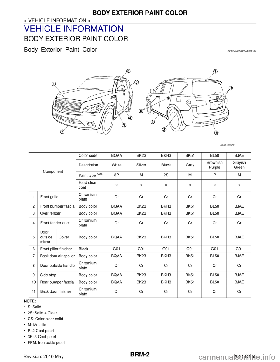
FPM: Iron oxide pearl Component
Color code BQAA BK23 BKH3 BK51 BL50 BJAE
Description White Silver Black Gray
Brownish
Purple Grayish
Green
Paint type
note3P M 2S M P M
Hard clear
coat ××××××
1 Front grille Chromium
plateCr Cr Cr Cr Cr Cr
2 Front bumper fascia Body color BQAA BK23 BKH3 BK51 BL50 BJAE
3 Over fender Body color B QAA BK23 BKH3 BK51 BL50 BJAE
4 Front fender duct Chromium
plate
Cr Cr Cr Cr Cr Cr
5 Door
outside
mirror
Cover Body color BQAA BK23 BKH3 BK51 BL50 BJAE
6 Front pillar finisher Black G01 G01 G01 G01 G01 G01
7 Back door air spoiler Body color BQAA BK23 BKH3 BK51 BL50 BJAE
8 Door outside handle Chromium
plate
Cr Cr Cr Cr Cr Cr
9 Side step Body color BQAA BK23 BKH3 BK51 BL50 BJAE
10 Rear bumper fascia Body color BQAA BK23 BKH3 BK51 BL50 BJAE
11 Back door finisher Chromium
plateCr Cr Cr Cr Cr Cr
JSKIA1965ZZ
Revision: 2010 May2011 QX56
Page 678 of 5598

BODY EXTERIOR PAINT COLORBRM-3
< VEHICLE INFORMATION >
C
DE
F
G H
I
J
L
M A
B
BRM
N
O P
RM, RPM: Multi flex color
TPM: Titanium pearl metallic
TM: Micro titanium metallic
PM: Pearl metallic
Revision: 2010 May2011 QX56
Page 679 of 5598

BRM-4
< PRECAUTION >
REPAIRING HIGH STRENGTH STEEL
PRECAUTION
REPAIRING HIGH STRENGTH STEEL
High Strength Steel (HSS)INFOID:0000000006248484
High strength steel is used for body panels in order to reduce vehicle weight.
Accordingly, precautions in repairing automotive bodies made of high strength steel are described below:
Read the following precautions when repairing HSS:
1. Additional points to consider
Tensile strength Major applicable parts 440 - 780 MPa Rear floor reinforcement
2nd seat mounting member assembly
Front seat mounting rear crossmember assembly
Front floor reinforcement
2nd crossmember (Lower)
Side radiator core support
Radiator core support main assembly
Front side member assembly
4th crossmember
2nd seat mounting crossmember
Rear side member
Rear crossmember
Inner side roof rail
Upper inner front pillar
Inner center pillar
Upper front pillar reinforcement
Lower center pillar brace
Front pillar brace
Outer sill reinforcement
Front roof rail
Rear roof rail
Radiator guard crossmember assembly
2nd crossmember assembly
2nd crossmember reinforcement
Front side member assembly
Front bound bumper bracket assembly
Lower front link mounting bracket assembly
Center side member assembly
Fuel tank protector assembly
Rear suspension mounting bracket assembly
Rear shock absorber bracket assembly
Rear side member assembly
Rear end gusset
Rear end crossmember assembly
980 - 1350 MPa Lower dash center reinforcement
(Lower dash Component part)
Inner sill
Rear seat crossmember
(2nd seat mounting crossmember component part)
Inner center pillar (Upper)
Upper outer center pillar reinforcement
(Lower center pillar brace component part)
Front bumper crossmember assembly
Revision: 2010 May2011 QX56
Page 680 of 5598
REPAIRING HIGH STRENGTH STEELBRM-5
< PRECAUTION >
C
DE
F
G H
I
J
L
M A
B
BRM
N
O P
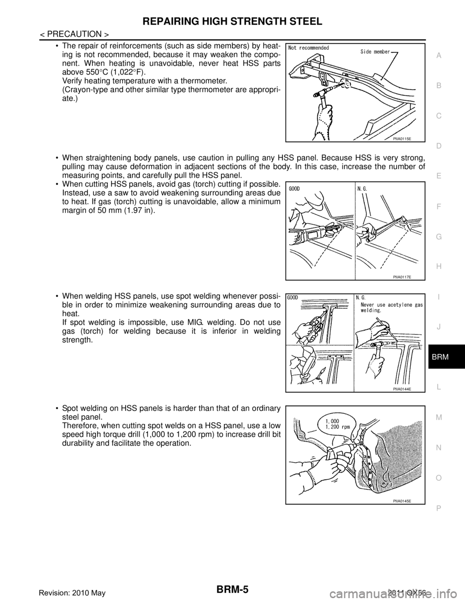
The repair of reinforcements (such as side members) by heat- ing is not recommended, because it may weaken the compo-
nent. When heating is unavoidable, never heat HSS parts
above 550 °C (1,022 °F).
Verify heating temperature with a thermometer.
(Crayon-type and other similar type thermometer are appropri-
ate.)
When straightening body panels, use caution in pul ling any HSS panel. Because HSS is very strong,
pulling may cause deformation in adjacent sections of the body. In this case, increase the number of
measuring points, and carefully pull the HSS panel.
When cutting HSS panels, avoid gas (torch) cutting if possible.
Instead, use a saw to avoid weakening surrounding areas due
to heat. If gas (torch) cutting is unavoidable, allow a minimum
margin of 50 mm (1.97 in).
When welding HSS panels, use spot welding whenever possi- ble in order to minimize weakening surrounding areas due to
heat.
If spot welding is impossible, use MIG. welding. Do not use
gas (torch) for welding because it is inferior in welding
strength.
Spot welding on HSS panels is harder than that of an ordinary steel panel.
Therefore, when cutting spot welds on a HSS panel, use a low
speed high torque drill (1,000 to 1,200 rpm) to increase drill bit
durability and facilitate the operation.
PIIA0115E
PIIA0117E
PIIA0144E
PIIA0145E
Revision: 2010 May2011 QX56
Page 682 of 5598
REPAIRING MATERIALBRM-7
< PREPARATION >
C
DE
F
G H
I
J
L
M A
B
BRM
N
O P
PREPARATION
REPAIRING MATERIAL
Foam RepairINFOID:0000000006248486
During factory body assembly, foam insulators are installed in certain body panels and locations around the
vehicle. Use the following procedure(s) to r eplace any factory-installed foam insulators.
URETHANE FOAM APPLICATIONS
Use commercially available Urethane foam for sealant (foam material) repair of material used on vehicle.
Read instructions on product for fill procedures.
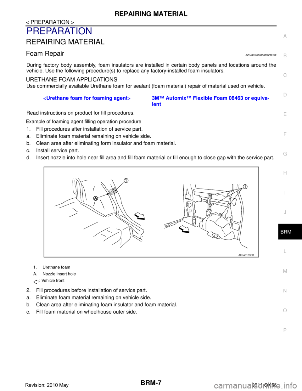
Example of foaming agent filling operation procedure
1. Fill procedures after installation of service part.
a. Eliminate foam material remaining on vehicle side.
b. Clean area after eliminating form insulator and foam material.
c. Install service part.
d. Insert nozzle into hole near fill area and fill foam ma terial or fill enough to close gap with the service part.
2. Fill procedures before installation of service part.
a. Eliminate foam material remaining on vehicle side.
b. Clean area after eliminating foam insulator and foam material.
c. Fill foam material on wheelhouse outer side.
Automix™ Flexible Foam 08463 or equiva-
lent
1. Urethane foam
A. Nozzle insert hole
: Vehicle front
JSKIA0129GB
Revision: 2010 May2011 QX56
Page 690 of 5598
CORROSION PROTECTIONBRM-15
< REMOVAL AND INSTALLATION >
C
DE
F
G H
I
J
L
M A
B
BRM
N
O P
REMOVAL AND INSTALLATION
CORROSION PROTECTION
DescriptionINFOID:0000000006248490
To provide improved corrosion prevention, the follo wing anti-corrosive measures have been implemented in
NISSAN production plants. When repairing or replacing body panels, it is necessary to use the same anti-cor-
rosive measures.
Anti-Corrosive Precoated Steel (Galvannealed Steel)
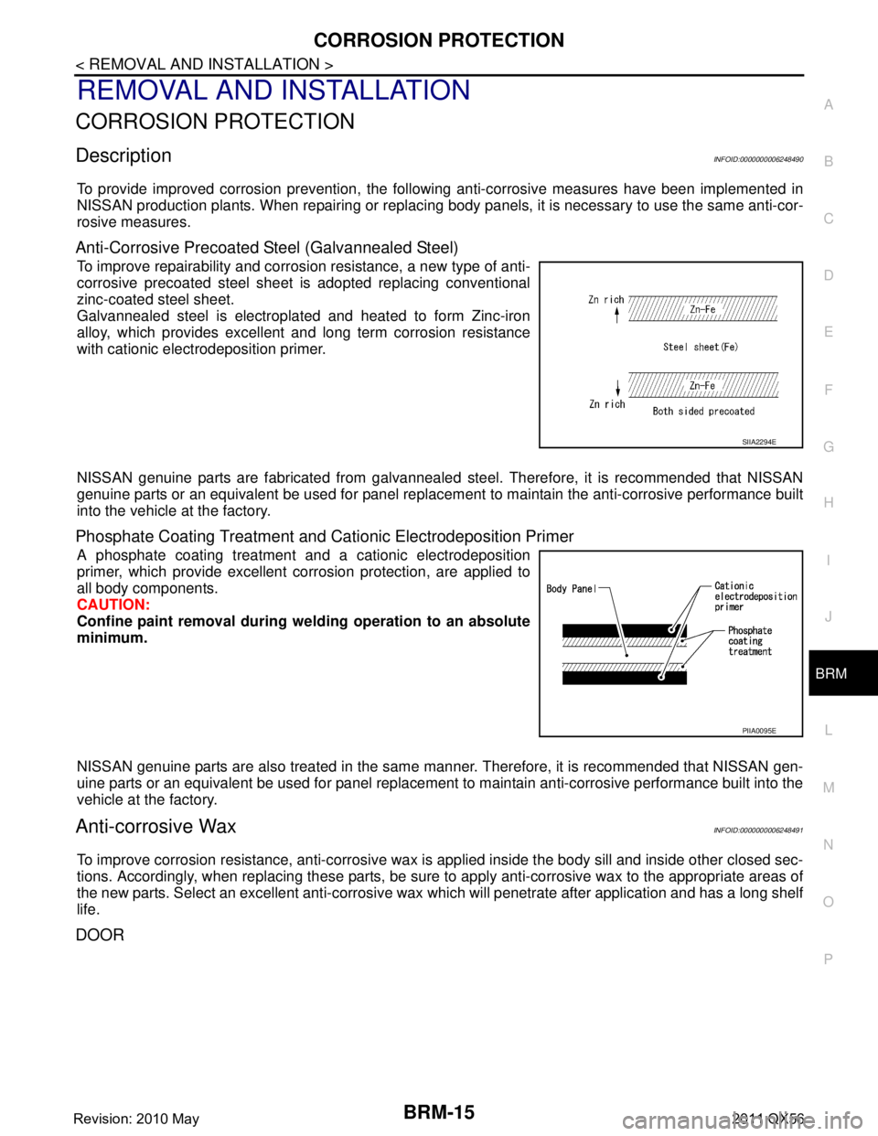
To improve repairability and corrosi on resistance, a new type of anti-
corrosive precoated steel sheet is adopted replacing conventional
zinc-coated steel sheet.
Galvannealed steel is electroplated and heated to form Zinc-iron
alloy, which provides excellent and long term corrosion resistance
with cationic electrodeposition primer.
NISSAN genuine parts are fabricated from galvannealed steel. Therefore, it is recommended that NISSAN
genuine parts or an equivalent be used for panel replacem ent to maintain the anti-corrosive performance built
into the vehicle at the factory.
Phosphate Coating Treatment and Cationic Electrodeposition Primer
A phosphate coating treatment and a cationic electrodeposition
primer, which provide excellent corrosion protection, are applied to
all body components.
CAUTION:
Confine paint removal during we lding operation to an absolute
minimum.
NISSAN genuine parts are also treated in the same manner. Therefore, it is recommended that NISSAN gen-
uine parts or an equivalent be used for panel replacement to maintain anti-corrosive performance built into the
vehicle at the factory.
Anti-corrosive WaxINFOID:0000000006248491
To improve corrosion resistance, anti-corrosive wax is applied inside the body sill and inside other closed sec-
tions. Accordingly, when replacing these parts, be sure to apply anti-corrosive wax to the appropriate areas of
the new parts. Select an excellent anti-corrosive wax which will penetrate after application and has a long shelf
life.
DOOR
SIIA2294E
PIIA0095E
Revision: 2010 May2011 QX56
Page 693 of 5598
BRM-18
< REMOVAL AND INSTALLATION >
CORROSION PROTECTION
Body Sealing
INFOID:0000000006248494
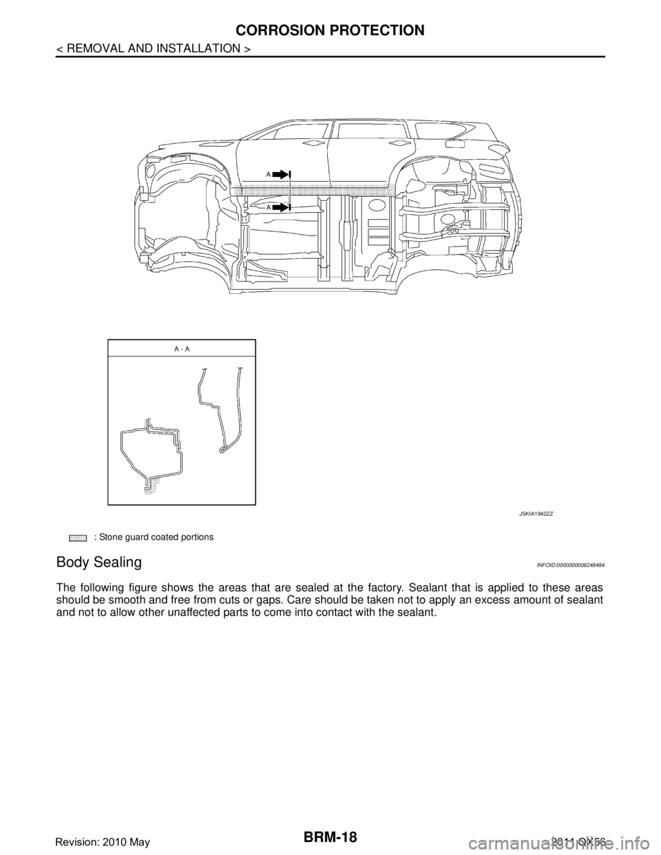
The following figure shows the areas that are sealed at the factory. Sealant that is applied to these areas
should be smooth and free from cuts or gaps. Care s hould be taken not to apply an excess amount of sealant
and not to allow other unaffected parts to come into contact with the sealant.
: Stone guard coated portions
JSKIA1942ZZ
Revision: 2010 May2011 QX56