coolant reservoir INFINITI QX56 2011 Factory Owner's Manual
[x] Cancel search | Manufacturer: INFINITI, Model Year: 2011, Model line: QX56, Model: INFINITI QX56 2011Pages: 5598, PDF Size: 94.53 MB
Page 2663 of 5598

ENGINE ASSEMBLYEM-101
< UNIT REMOVAL AND INSTALLATION >
C
DE
F
G H
I
J
K L
M A
EM
NP
O
5. Remove A/T assembly. Refer to
TM-205, "2WD : Exploded View" (2WD models) or TM-208, "4WD :
Exploded View" (4WD models).
6. Remove steering gear assembly. Refer to ST-41, "
Exploded View".
7. Remove front final drive assembly. Refer to DLN-162, "
Exploded View".
8. Remove exhaust manifold. Refer to EM-40, "
Exploded View".
9. Remove alternator. Refer to CHG-25, "
Exploded View".
Engine Room LH
1. Remove air cleaner and air duct. Refer to EM-27, "Exploded View".
2. Remove A/C compressor. Refer to HA-30, "
Exploded View".
3. Disconnect fuel feed hose and EVAP hose. Refer to EM-43, "
Exploded View".
CAUTION:
Fit plugs onto disconnected hoses to prevent fuel leakage.
Engine Room RH
1. Remove power steering oil pump and reservoir tank. Refer to ST-48, "Exploded View".
2. Disconnect heater hose at heater core side, and fit a plug onto hose end to prevent engine coolant leak-
age.
3. Disconnect ground cable.
4. Disconnect all clips and connectors of the engine harness from vehicle side.
Removal Work
1. Install alternator bracket. Refer to CHG-25, "Exploded View".
Temporarily tighten mounting bolts.
2. Remove intake manifold. Refer to EM-30, "
Exploded View".
3. Remove starter motor. Refer to STR-17, "
Exploded View".
4. Install engine slingers.
5. Lift using a hoist and secure the engine in position.
6. Remove engine mounting bracket (LH, RH) and engine mounting insulator (LH, RH). Refer to EM-98,
"Exploded View".
7. Remove the engine from the vehi cle, avoid interference with the
vehicle body.
CAUTION:
Before and during lifting, always check that any har-
nesses are left connected.
Never damage engine mounti ng insulator and avoid oil/
grease smearing or spills onto engine mounting insulator.
A Engine front slinger (bank 2) B Engine rear slinger C Engine front slinger (bank 1)
Slinger bolts:
: 45.0 N·m (4.6 kg-m, 33 ft-lb)
JPBIA3970ZZ
JPBIA3497ZZ
Revision: 2010 May2011 QX56
Page 3246 of 5598
![INFINITI QX56 2011 Factory Owners Manual
HAC-140
< SYMPTOM DIAGNOSIS >[AUTOMATIC AIR CONDITIONING]
INSUFFICIENT HEATING
INSUFFICIENT HEATING
FRONT AIR CONDITIONER
FRONT AIR CONDITIONER : DescriptionINFOID:0000000006275990
Symptom Insuffici](/img/42/57033/w960_57033-3245.png "INFINITI QX56 2011 Factory Owners Manual
HAC-140
< SYMPTOM DIAGNOSIS >[AUTOMATIC AIR CONDITIONING]
INSUFFICIENT HEATING
INSUFFICIENT HEATING
FRONT AIR CONDITIONER
FRONT AIR CONDITIONER : DescriptionINFOID:0000000006275990
Symptom Insuffici")
HAC-140
< SYMPTOM DIAGNOSIS >[AUTOMATIC AIR CONDITIONING]
INSUFFICIENT HEATING
INSUFFICIENT HEATING
FRONT AIR CONDITIONER
FRONT AIR CONDITIONER : DescriptionINFOID:0000000006275990
Symptom Insufficient heating
No warm air comes out. (Air flow volume is normal.)
FRONT AIR CONDITIONER
: Diagnosis ProcedureINFOID:0000000006275991
NOTE:
Perform self-diagnoses with on board diagnosis and CO NSULT-III before performing symptom diagnosis. If
DTC is detected, perform the corresponding diagnosis.
1.CHECK COOLING SYSTEM
1. Check engine coolant level and check leakage. Refer to CO-8, "
Inspection".
2. Check reservoir tank cap. Refer to CO-11, "
RESERVOIR TANK CAP : Inspection".
3. Check water flow sounds of the engine coolant. Refer to CO-9, "
Refilling".
Is the inspection result normal?
YES >> GO TO 2.
NO >> Refill engine coolant and repair or repl ace parts depending on the inspection results.
2.CHECK HEATER HOSE
Check installation of heater hose by visually or touching.
Is the inspection result normal?
YES >> GO TO 3.
NO >> Repair or replace parts depending on the inspection results.
3.CHECK FRONT HEATER CORE
1. Check temperature of inlet hose and outlet hose of front heater core.
2. Check that inlet side of front heater core is hot and t he outlet side is slightly lower than/almost equal to the
inlet side.
CAUTION:
Always perform the temperature in spection in a short period of time because the engine coolant
temperature is very hot.
Is the inspection result normal?
YES >> GO TO 4.
NO >> Replace front heater core. Refer to HA-44, "
HEATER CORE : Removal and Installation".
4.CHECK AIR LEAKAGE FROM EACH DUCT
Check duct and nozzle, etc. of front air conditioning system for air leakage.
Is the inspection result normal?
YES >> GO TO 5.
NO >> Repair or replace parts depending on the inspection results.
5.CHECK SETTING OF TEMPERATURE SETTING TRIMMER (FRONT)
1. Check setting value of temperature setting trimmer (front). Refer to HAC-68, "
FRONT AUTOMATIC AIR
CONDITIONING SYSTEM : Temperature Setting Trimmer (Front)".
2. Check that temperature setting trimmer (front) is set to “ − direction”.
NOTE:
The control temperature can be set by t he temperature setting trimmer (front).
3. Set difference between the set temperature and control temperature to “0”.
Are the symptoms solved?
YES >> INSPECTION END
NO >> Replace A/C auto amp.. Refer to HAC-146, "
Removal and Installation".
REAR AIR CONDITIONER
Revision: 2010 May2011 QX56
Page 3247 of 5598
![INFINITI QX56 2011 Factory Owners Manual
INSUFFICIENT HEATINGHAC-141
< SYMPTOM DIAGNOSIS > [AUTOMATIC AIR CONDITIONING]
C
D
E
F
G H
J
K L
M A
B
HAC
N
O P
REAR AIR CONDITIONER : DescriptionINFOID:0000000006275992
Symptom
Insufficient heati](/img/42/57033/w960_57033-3246.png "INFINITI QX56 2011 Factory Owners Manual
INSUFFICIENT HEATINGHAC-141
< SYMPTOM DIAGNOSIS > [AUTOMATIC AIR CONDITIONING]
C
D
E
F
G H
J
K L
M A
B
HAC
N
O P
REAR AIR CONDITIONER : DescriptionINFOID:0000000006275992
Symptom
Insufficient heati")
INSUFFICIENT HEATINGHAC-141
< SYMPTOM DIAGNOSIS > [AUTOMATIC AIR CONDITIONING]
C
D
E
F
G H
J
K L
M A
B
HAC
N
O P
REAR AIR CONDITIONER : DescriptionINFOID:0000000006275992
Symptom
Insufficient heating
No warm air comes out. (Air flow volume is normal.)
REAR AIR CONDITIONER : Diagnosis ProcedureINFOID:0000000006275993
CAUTION:
Perform the self-diagnoses with on board diagnosi s and CONSULT-III before performing symptom
diagnosis. If any malfunction result or DTC is detected, perform the corresponding diagnosis.
1.CHECK COOLING SYSTEM
1. Check engine coolant level and check leakage. Refer to CO-8, "
Inspection".
2. Check reservoir tank cap. Refer to CO-11, "
RESERVOIR TANK CAP : Inspection".
3. Check water flow sounds of the engine coolant. Refer to CO-9, "
Refilling".
Is the inspection result normal?
YES >> GO TO 2.
NO >> Refill the engine coolant and repair or replace the parts depending on the inspection results.
2.CHECK HEATER HOSE
Check installation of heater hose by visually or touching.
Is the inspection result normal?
YES >> GO TO 3.
NO >> Repair or replace parts depending on the inspection results.
3.CHECK REAR HEATER CORE
1. Check temperature of inlet hose and outlet hose of rear heater core.
2. Check that the inlet side of rear heater core is hot and the outlet side is slightly lower than/almost equal to
the inlet side.
CAUTION:
Always perform the temperature inspection in a sh ort period of time because the engine coolant
temperature is very hot.
Is the inspection result normal?
YES >> GO TO 4.
NO >> Replace rear heater core. Refer to HA-48, "
HEATER CORE : Removal and Installation".
4.CHECK AIR LEAKAGE FROM EACH DUCT
Check duct and nozzle, etc. of the rear air conditioning system for air leakage.
Is the inspection result normal?
YES >> GO TO 5.
NO >> Repair or replace parts depending on the inspection results.
5.CHECK SETTING OF TEMPERATURE SETTING TRIMMER (REAR)
1. Check setting value of temperature setting trimmer (rear). Refer to HAC-69, "
REAR AUTOMATIC AIR
CONDITIONING SYSTEM : Temperature Setting Trimmer (Rear)".
2. Check that the temperature setting trimmer is set to “ − direction”.
NOTE:
The control temperature can be set by the temperature setting trimmer (rear).
3. Set the difference between the set temperature (rear) and control temperature to “0”.
Are the symptoms solved?
YES >> INSPECTION END
NO >> Replace A/C auto amp.. Refer to HAC-146, "
Removal and Installation".
Revision: 2010 May2011 QX56
Page 3671 of 5598

MA-1
MAINTENANCE
C
DE
F
G H
I
J
K L
M B
MA
SECTION MA
N
O A
CONTENTS
MAINTENANCE
PREPARATION .............
...............................3
PREPARATION .............................................. .....3
Special Service Tool ........................................... ......3
Commercial Service Tool ..........................................3
PERIODIC MAINTENANCE ..........................4
GENERAL MAINTENANCE ........................... .....4
Explanation of General Maintenance .................. ......4
PERIODIC MAINTENANCE ................................6
Introduction of Periodic Maintenance .................. ......6
Schedule 1 ................................................................6
Schedule 2 ................................................................8
RECOMMENDED FLUIDS AND LUBRI-
CANTS ................................................................
10
Fluids and Lubricants .......................................... ....10
Engine Oil Recommendation ..................................10
Anti-Freeze Coolant Mixture Ratio ..........................11
ENGINE MAINTENANCE ...................................12
DRIVE BELTS ....................................................... ....12
DRIVE BELTS : Exploded View ..............................12
DRIVE BELTS : Checking .......................................12
DRIVE BELTS : Tension Adjustment .....................12
ENGINE COOLANT ............................................... ....12
ENGINE COOLANT : Inspection .............................12
ENGINE COOLANT : Draining ................................13
ENGINE COOLANT : Refilling ................................13
ENGINE COOLANT : Flushing ...............................15
RESERVOIR TANK CAP ..........................................15
RESERVOIR TANK CAP : Inspection ................. ....15
RADIATOR ............................................................ ....16
RADIATOR : Inspection ..........................................16
FUEL LINES .......................................................... ....16
FUEL LINES : Inspection ........................................17
AIR CLEANER FILTER ......................................... ....17
AIR CLEANER FILTER : Removal and Installation
....
17
ENGINE OIL ........................................................... ....17
ENGINE OIL : Draining ............................................17
ENGINE OIL : Refilling ............................................17
OIL FILTER ............................................................ ....18
OIL FILTER : Removal and Installation ...................18
SPARK PLUG ........................................................ ....18
SPARK PLUG : Removal and Installation ...............19
SPARK PLUG : Inspection ......................................19
EVAP VAPOR LINES ............................................ ....20
EVAP VAPOR LINES : Inspection ...........................20
CHASSIS MAINTENANCE ...............................21
EXHAUST SYSTEM . ..................................................21
EXHAUST SYSTEM : Inspec tion ............................21
A/T FLUID .............................................................. ....21
A/T FLUID : Inspection ............................................21
TRANSFER FLUID ................................................ ....21
TRANSFER FLUID : Inspection ..............................21
TRANSFER FLUID : Draining .................................21
TRANSFER FLUID : Refilling ..................................22
FRONT PROPELLER SHAFT: 2F P15 ................. ....22
FRONT PROPELLER SHAFT: 2F P15 : Inspec-
tion ...........................................................................
22
REAR PROPELLER SHAFT: 2F P26 .................... ....23
REAR PROPELLER SHAFT: 2F P26 : Inspection ....23
REAR PROPELLER SHAFT: 2S1410 ................... ....23
REAR PROPELLER SHAFT: 2S1410 : Inspection ....23
FRONT DIFFERENTIAL GEAR OIL: R180A ........ ....24
FRONT DIFFERENTIAL GEAR OIL: R180A : In-
spection ...................................................................
24
Revision: 2010 May2011 QX56
Page 3675 of 5598

GENERAL MAINTENANCEMA-5
< PERIODIC MAINTENANCE >
C
DE
F
G H
I
J
K L
M B
MA
N
O A
UNDER THE HOOD AND VEHICLE
The maintenance items listed here should
be checked periodically (e.g. each time you check the engine oil or refuel).
Seats Check seat position controls such as seat adjusters, seatback recliner, etc. to
make sure they operate smoothly and that all latches lock securely in every po-
sition. Check that the head restrains move up and down smoothly and that the
locks (if equipped) hold securely in all latched positions. Check that the latches
lock securely for folding-down rear seatbacks. —
Seat belts Check that all parts of the seat belt system (e.g. buckles, anchors, adjusters
and retractors) operate properly and smoothly, and are installed securely.
Check the belt webbing for cuts, fraying, wear or damage. MA-34
Accelerator pedal
Check the pedal for smooth operation and make sure the pedal does not catch
or require uneven effort. Keep the floor mats away from the pedal. —
Brakes Check that the brake does not pull the vehicle to one side when applied. —
Brake pedal and
booster Check the pedal for smooth operation and make sure it has the proper distance
under it when depressed fully. Check the brake booster function. Be sure to
keep the floor mats away from the pedal. BR-7
BR-15
Parking brake
Check that the lever or pedal has the proper travel and make sure that the ve-
hicle is held securely on a fairly steep hill when only the parking brake is ap-
plied. PB-3
Automatic transmis-
sion “Park” mecha-
nismCheck that the lock release button on the selector lever operates properly and
smoothly. On a fairly steep hill check that the vehicle is held securely with the
selector lever in the P (Park) position without applying any brakes.
—
Item
Reference page
Item Reference page
Windshield washer
fluid Check that there is adequate fluid in the tank. —
Engine coolant level Check the coolant level when the engine is cold. MA-12
Radiator and hosesCheck the front of the radiator and clean off any dirt, insects, leaves, etc., that
may have accumulated. Make sure the hoses have no cracks, deformation, de-
terioration or loose connections. MA-16
Brake fluid levels
Make sure that the brake fluid level is between the “MAX” and “MIN” lines on the
reservoir(s). MA-28
Battery
Check the fluid level in each cell. It should be between the “MAX” and “MIN”
lines. Vehicles operated in high temperatures or under severe conditions re-
quire frequent checks of the battery fluid level. PG-159
Engine drive belts
Make sure that no belt is frayed, worn, cracked or oily. MA-12
Engine oil levelCheck the level on the oil level gauge after parking the vehicle on a level spot
and turning off the engine. LU-7
Power steering fluid
level and linesCheck the level on the dipstick with the engine off. Check the lines for improper
attachment, leaks, cracks, etc.
MA-32
Exhaust system
Make sure there are no loose supports, cracks or holes. If the sound of the ex-
haust seems unusual or there is a smell of exhaust fumes, immediately locate
the trouble and correct it. MA-21
Underbody
The underbody is frequently exposed to corrosive substances such as those
used on icy roads or to control dust. It is very important to remove these sub-
stances, otherwise rust will form on the floor pan, frame, fuel lines and around
the exhaust system. At the end of winter, the underbody should be thoroughly
flushed with plain water, being careful to clean those areas where mud and dirt
can easily accumulate. —
Fluid leaks Check under the vehicle for fuel, oil, water or other fluid leaks after the vehicle
has been parked for a while. Water dripping from the air conditioner after use is
normal. If you should notice any leaks or gasoline fumes are evident, check for
the cause and correct it immediately. —
Revision: 2010 May2011 QX56
Page 3680 of 5598

MA-10
< PERIODIC MAINTENANCE >
RECOMMENDED FLUIDS AND LUBRICANTS
RECOMMENDED FLUIDS AND LUBRICANTS
Fluids and LubricantsINFOID:0000000006220904
*1: For further details, see “Engine Oil Recommendation”.
*2: Using automatic transmission fluid other than Genuine NISSAN Matic S ATF will cause deterioration in driveability and autom atic
transmission durability, and may damage the automatic transmission, which is not covered by the INFINITI new vehicle limited wa rranty.
*3: DEXRON™ VI type ATF may also be used.
*4: Available in mainland U.S.A. through an INFINITI dealer.
*5: Using transfer fluid other t han Genuine NISSAN Transfer Fluid will damage the transfer , which is not covered by the INFINITI new
vehicle limited warranty. See an INFINITI retailer for recommended transfer fluid.
*6: For hot climates, Viscosity SAE 90 is suitable for ambient temperatures above 0 °C (32 °F)
*7: See an INFINITI dealer for service for synthetic oil.
*8: Using Hydraulic Suspen sion fluid other than Genuine NISSAN Hydraulic Susp ension fluid will damage the Hydraulic Suspension,
which is not covered by the INFINITI new vehicle limited warranty. See an INFINITI retailer for recommended hydraulic suspensio n fluid.
*9: The fluid capacity is the reference value.
Engine Oil RecommendationINFOID:0000000006287732
NISSAN recommends the use of an energy conservi ng oil in order to improve fuel economy.
Select only engine oils that meet the American Petroleum Institute (API) certification and International Lubri-
cant Standardization and Approval Committee (ILSAC) ce rtification and SAE viscosity standard. These oils
have the API certification mark on t he front of the container. Oils which do not have the specified quality label
should not be used as they could cause engine damage.
Capacity (Approximate) Recommended Fluids/Lubricants
US measure Imp measure Liter
Engine oil
Drain and refill With oil filter change 6-7/8 qt 5-3/4 qt 6.5
Engine oil with API Certification Mark
*1
Viscosity SAE 5W-30
Without oil filter change 6-4/8 qt 5-1/2 qt 6.2
Dry engine (engine overhaul) 8 qt 6-3/4 qt 7.6
Cooling system With reservoir tank 15
-6/8 qt 13-1/8 qt 14.9
Genuine NISSAN Long Life Antifreeze/
Coolant (blue) or equivalent
Reservoir tank 1 qt 7/8 qt 1.0
Automatic transmission fluid 10-5/8 qt
*98-3/4 qt*910.0*9Genuine NISSAN Matic S ATF *2
Power steering fluid 1-1/8 qt 7/8 qt 1.0
Genuine NISSAN PSF or equivalent*3
Brake fluid — — —Genuine NISSAN Super Heavy Duty
Brake Fluid*4 or equivalent DOT 3 (US FM-
VSS No. 116)
Transfer fluid 3-1/8 pt 2-5/8 pt 1.5 Genuine NISSAN Transfer Fluid for
ATX90A transfer*
5
Differential gear oilFront 1-5/8 pt 1-3/8 pt 0.75
Genuine NISSAN Differential Oil Hypoid
Super GL-5 80W-90 or API GL-5, Viscosity
SAE 80W-90*
6
Rear 3/3/4 pt 3-1/8 pt 1.75Genuine NISSAN Differential Oil Synthetic
75W-90 or API GL-5 synthetic gear oil, Vis-
cosity SAE 75W-90*7
Suspension fluid — — —
Genuine NISSAN Hydraulic Suspension
Fluid*8
Multi-purpose grease — — — NLGI No. 2 (Lithium soap base)
Revision: 2010 May2011 QX56
Page 3683 of 5598

ENGINE MAINTENANCEMA-13
< PERIODIC MAINTENANCE >
C
DE
F
G H
I
J
K L
M B
MA
N
O A
Check if the reservoir tank engine coolant level is within the “MIN”
to “MAX” when the engine is cool.
Adjust the engine coolant level if necessary. WARNING:
Never remove reservoir tank cap when engine is hot.
LEAKAGE
To check for leakage, apply pressure to the cooling system with theradiator cap tester and radiator cap tester adapter (commercial
service tool) (A).
WARNING:
Never remove radiator cap and reservoir tank cap when
engine is hot. Serious burns could occur from high-pressure
engine coolant escaping from water inlet.
CAUTION:
Higher test pressure than specified may cause radiator dam-
age.
NOTE:
In a case that engine coolant decreas es, fill radiator with engine coolant.
If anything is found, repair or replace damaged parts.
ENGINE COOLANT : DrainingINFOID:0000000006394845
WARNING:
Never remove radiator cap and reservoir tank cap when engine is hot. Serious burns could occur
from high-pressure engine co olant escaping from radiator.
Wrap a thick cloth around the caps. Slowly turn them a quarter of a turn to release built-up pressure.
Carefully remove the caps by turning it all the way.
1. Open radiator drain plug (1) at the bottom of radiator, and then remove radiator cap and reservoir tank cap.
When draining all of engine cool ant in the system, open water drai n plug on cylinder block. Refer
to EM-103, "
Setting".
2. Remove reservoir tank if necessary, and drain engine coolant and clean reservoir tank before installing.
3. Check drained engine coolant for contaminants such as rust, corrosion or discoloration. If contaminated, flush the engine cooling system. Refer to MA-15, "
ENGINE COOLANT : Flushing".
ENGINE COOLANT : RefillingINFOID:0000000006394846
1. Install reservoir tank if removed, and radiator drain plug.
CAUTION:
Be sure to clean drain plug and install with new O-ring. Refer to CO-13, "
Exploded View".
A: MAX
B: MIN
JPBIA0102ZZ
Testing pressure : Refer to CO-23, "Radiator".
JPBIA3432ZZ
2 : Front under cover
: Vehicle front
JPBIA3430ZZ
Revision: 2010 May2011 QX56
Page 3684 of 5598

MA-14
< PERIODIC MAINTENANCE >
ENGINE MAINTENANCE
If water drain plug on cylinder block is removed, close and tighten it. Refer to EM-107, "Disassem-
bly and Assembly".
2. Check that each hose clamp is firmly tightened.
3. Remove air relief plug (1) on heater hose.
4. Fill radiator, and reservoir tank, to specified level. Pour engine coolant through engine coolant filler neck
slowly of less than 3 (2-5/8 lmp qt) a minute to allow air
in system to escape.
Use Genuine NISSAN Long Life Antifreeze/Coolant or
equivalent mixed with water (d istilled or demineralized).
Refer to MA-10, "
Fluids and Lubricants".
5. When engine coolant overflows air relief hole on heater hose, install air relief plug with clamp. Then refill
radiator with engine coolant.
6. Install radiator cap.
7. Install reservoir tank cap.
8. Warm up engine until opening thermostat less than 3,000 rpm. Check thermostat opening condition by touching radiator hose (lower) to see a flow of warm water.
CAUTION:
Watch water temperature gauge so as not to overheat engine.
9. Stop the engine and cool down to less than approximately 50 °C (122 °F).
Cool down using fan to reduce the time.
If necessary, refill radiator up to filler neck with engine coolant.
10. Refill reservoir tank to “MAX” level line with engine coolant if necessary.
11. Repeat steps 6 through 10 two or more times with reservoir tank cap installed until engine coolant level no longer drops. : 1.96 N·m (0.2 kg-m, 17 in-lb)
2. Engine cover
: Vehicle front
JPBIA3429ZZ
Engine coolant capacity : Refer to CO-23,
"PeriodicalMaintenanceS
pecification".
(With reservoir tank at
“MAX” level)JPBIA0412ZZ
Reservoir tank engine
coolant capacity :Refer to
CO-23,
"PeriodicalMaintenanceSp
ecification".
(At “MAX” level)
A : MAX
B: MIN
JPBIA0102ZZ
Revision: 2010 May2011 QX56
Page 3685 of 5598

ENGINE MAINTENANCEMA-15
< PERIODIC MAINTENANCE >
C
DE
F
G H
I
J
K L
M B
MA
N
O A
12. Check cooling system for leakage with engine running.
13. Warm up the engine, and check for sound of engine coolant flow while running engine from idle up to
3,000 rpm with heater temperature controller se t at several position between “COOL” and “WARM”.
Sound may be noticeable at heater unit.
14. Repeat step 13 three times.
15. If sound is heard, bleed air from cooling system by repeating step 4, and steps from 6 to 14 until engine
coolant level no longer drops.
ENGINE COOLANT : FlushingINFOID:0000000006394847
1. Install reservoir tank if removed, and radiator drain plug. CAUTION:
Be sure to clean drain plug and install with new O-ring. Refer to CO-13, "
Exploded View".
If water drain plug on cylinder block is removed, close and tighten it. Refer to EM-107, "
Disassem-
bly and Assembly".
2. Remove air relief plug (1) on heater hose.
3. Fill radiator and reservoir tank with water until water spills from the air relief holes, then close air relief
plugs with clamp. Fill radiator and rese rvoir tank with water and reinstall caps.
4. Run the engine and warm it up to normal operating temperature.
5. Rev the engine two or three times under no-load.
6. Stop the engine and wait until it cools down.
7. Drain water from the system. Refer to MA-13, "
ENGINE COOLANT : Draining".
8. Repeat steps 1 through 7 until clear water begins to drain from radiator.
RESERVOIR TANK CAP
RESERVOIR TANK CAP : InspectionINFOID:0000000006394848
Check valve seat of reservoir tank cap.
- Check if valve seat (A) is swollen to the extent that the edge of the metal plunger (B) cannot be seen when watching it vertically from
the top.
- Check if valve seat has no soil and damage. : 1.96 N·m (0.2 kg-m, 17 in-lb)
2. Engine cover
: Vehicle front
JPBIA3429ZZ
JPBIA0108ZZ
Revision: 2010 May2011 QX56
Page 3686 of 5598
MA-16
< PERIODIC MAINTENANCE >
ENGINE MAINTENANCE
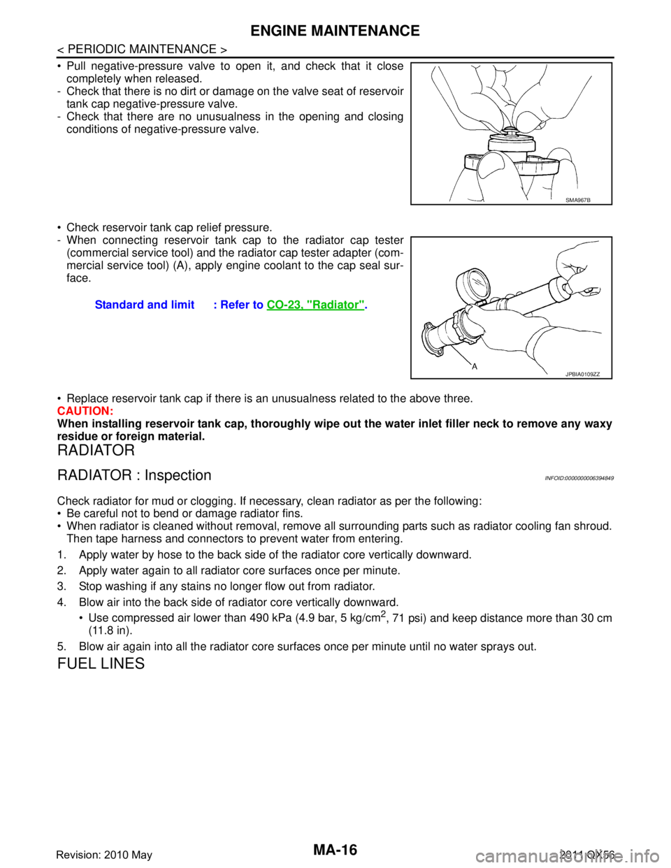
Pull negative-pressure valve to open it, and check that it closecompletely when released.
- Check that there is no dirt or damage on the valve seat of reservoir
tank cap negative-pressure valve.
- Check that there are no unusualness in the opening and closing conditions of negative-pressure valve.
Check reservoir tank cap relief pressure.
- When connecting reservoir tank cap to the radiator cap tester (commercial service tool) and the radiator cap tester adapter (com-
mercial service tool) (A), apply engine coolant to the cap seal sur-
face.
Replace reservoir tank cap if there is an unusualness related to the above three.
CAUTION:
When installing reservoir tank cap, thoroughly wipe out the water inlet filler neck to remove any waxy
residue or foreign material.
RADIATOR
RADIATOR : InspectionINFOID:0000000006394849
Check radiator for mud or clogging. If nec essary, clean radiator as per the following:
Be careful not to bend or damage radiator fins.
When radiator is cleaned without removal, remove all surrounding parts such as radiator cooling fan shroud. Then tape harness and connectors to prevent water from entering.
1. Apply water by hose to the back side of the radiator core vertically downward.
2. Apply water again to all radiator core surfaces once per minute.
3. Stop washing if any stains no longer flow out from radiator.
4. Blow air into the back side of radiator core vertically downward. Use compressed air lower than 490 kPa (4.9 bar, 5 kg/cm
2, 71 psi) and keep distance more than 30 cm
(11.8 in).
5. Blow air again into all the radiator core su rfaces once per minute until no water sprays out.
FUEL LINES
SMA967B
Standard and limit : Refer to CO-23, "Radiator".
JPBIA0109ZZ
Revision: 2010 May2011 QX56