wheel INFINITI QX56 2011 Factory Service Manual
[x] Cancel search | Manufacturer: INFINITI, Model Year: 2011, Model line: QX56, Model: INFINITI QX56 2011Pages: 5598, PDF Size: 94.53 MB
Page 4271 of 5598
RSU-16
< REMOVAL AND INSTALLATION >
FRONT LOWER LINK
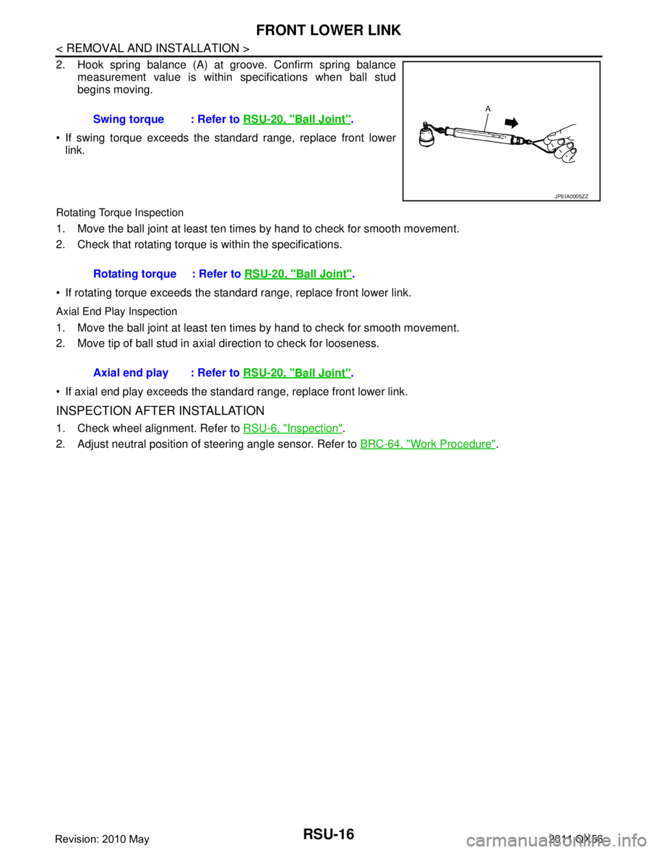
2. Hook spring balance (A) at groove. Confirm spring balancemeasurement value is within specifications when ball stud
begins moving.
If swing torque exceeds the standard range, replace front lower link.
Rotating Torque Inspection
1. Move the ball joint at least ten times by hand to check for smooth movement.
2. Check that rotating torque is within the specifications.
If rotating torque exceeds the standar d range, replace front lower link.
Axial End Play Inspection
1. Move the ball joint at least ten times by hand to check for smooth movement.
2. Move tip of ball stud in axial direction to check for looseness.
If axial end play exceeds the standard range, replace front lower link.
INSPECTION AFTER INSTALLATION
1. Check wheel alignment. Refer to RSU-6, "Inspection".
2. Adjust neutral position of steering angle sensor. Refer to BRC-64, "
Work Procedure".
Swing torque : Refer to
RSU-20, "
Ball Joint".
JPEIA0005ZZ
Rotating torque : Refer to RSU-20, "Ball Joint".
Axial end play : Refer to RSU-20, "
Ball Joint".
Revision: 2010 May2011 QX56
Page 4273 of 5598
RSU-18
< UNIT REMOVAL AND INSTALLATION >
REAR SUSPENSION MEMBER
UNIT REMOVAL AND INSTALLATION
REAR SUSPENSION MEMBER
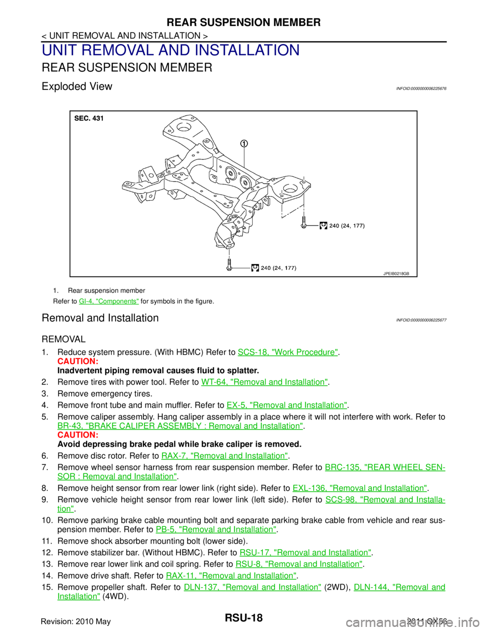
Exploded ViewINFOID:0000000006225676
Removal and InstallationINFOID:0000000006225677
REMOVAL
1. Reduce system pressure. (With HBMC) Refer to SCS-18, "Work Procedure".
CAUTION:
Inadvertent piping removal causes fluid to splatter.
2. Remove tires with power tool. Refer to WT-64, "
Removal and Installation".
3. Remove emergency tires.
4. Remove front tube and main muffler. Refer to EX-5, "
Removal and Installation".
5. Remove caliper assembly. Hang caliper assembly in a place where it will not interfere with work. Refer to BR-43, "
BRAKE CALIPER ASSEMBLY : Removal and Installation".
CAUTION:
Avoid depressing brake pedal wh ile brake caliper is removed.
6. Remove disc rotor. Refer to RAX-7, "
Removal and Installation".
7. Remove wheel sensor harness from rear suspension member. Refer to BRC-135, "
REAR WHEEL SEN-
SOR : Removal and Installation".
8. Remove height sensor from rear lower link (right side). Refer to EXL-136, "
Removal and Installation".
9. Remove vehicle height sensor from rear lower link (left side). Refer to SCS-98, "
Removal and Installa-
tion".
10. Remove parking brake cable mounting bolt and separa te parking brake cable from vehicle and rear sus-
pension member. Refer to PB-5, "
Removal and Installation".
11. Remove shock absorber mounting bolt (lower side).
12. Remove stabilizer bar. (Without HBMC). Refer to RSU-17, "
Removal and Installation".
13. Remove rear lower link and coil spring. Refer to RSU-8, "
Removal and Installation".
14. Remove drive shaft. Refer to RAX-11, "
Removal and Installation".
15. Remove propeller shaft. Refer to DLN-137, "
Removal and Installation" (2WD), DLN-144, "Removal and
Installation" (4WD).
1. Rear suspension member
Refer to GI-4, "
Components" for symbols in the figure.
JPEIB0218GB
Revision: 2010 May2011 QX56
Page 4274 of 5598
REAR SUSPENSION MEMBERRSU-19
< UNIT REMOVAL AND INSTALLATION >
C
DF
G H
I
J
K L
M A
B
RSU
N
O P
16. Remove final drive. Refer to DLN-201, "Removal and Installation".
17. Remove rear tube assembly A and rear tube assembly B. (With HBMC) Refer to SCS-44, "
REAR TUBE
ASSEMBLY : Removal and Installation".
18. Set suitable jack under rear suspension member.
19. Slowly lower jack, then remove rear suspension member, suspension arm, front lower link, wheel hub and housing from vehicle as a unit.
20. Remove mounting bolts and nuts, then remove suspension arm, front lower link, wheel hub and housing from rear suspension member.
21. Perform inspection after removal. Refer to RSU-19, "
Inspection and Adjustment".
INSTALLATION
Note the following, and install in the reverse order of the removal.
Perform the final tightening of each of parts under unladen conditions, which were removed when removing
rear suspension assembly.
Perform inspection after installation. Refer to RSU-19, "
Inspection and Adjustment".
Perform adjustment after installation. (With HBMC) Refer to RSU-19, "
Inspection and Adjustment".
Inspection and AdjustmentINFOID:0000000006225678
INSPECTION AFTER REMOVAL
Check rear suspension member for deformation, cracks, or any other damage. Replace if necessary.
INSPECTION AFTER INSTALLATION
1. Adjust parking brake operation (stroke). Refer to PB-3, "Inspection and Adjustment".
2. Check wheel alignment. Refer to RSU-6, "
Inspection".
3. Adjust neutral position of steering angle sensor. Refer to BRC-64, "
Work Procedure".
4. Adjust levelizer adjustment of height sensor. Refer to EXL-61, "
LEVELIZER ADJUSTMENT : Special
Repair Requirement".
5. Check standard vehicle height setting of vehicle height sensor. Refer to SCS-67, "
Work Procedure".
6. Check wheel sensor harness for proper connection. Refer to BRC-135, "
REAR WHEEL SENSOR :
Exploded View"
ADJUSTMENT AFTER INSTALLATION (WITH HBMC)
Bleed air from the HBMC. Refer to SCS-18, "Work Procedure".
Revision: 2010 May2011 QX56
Page 4275 of 5598
RSU-20
< SERVICE DATA AND SPECIFICATIONS (SDS)
SERVICE DATA AND SPECIFICATIONS (SDS)
SERVICE DATA AND SPECIFICATIONS (SDS)
SERVICE DATA AND SPECIFICATIONS (SDS)
Wheel AlignmentINFOID:0000000006225679
Measure value under unladen* conditions.
*: Fuel, engine coolant and lubricant are full. Spare tire, jack, hand tools and mats are in designated positions.
Ball JointINFOID:0000000006225680
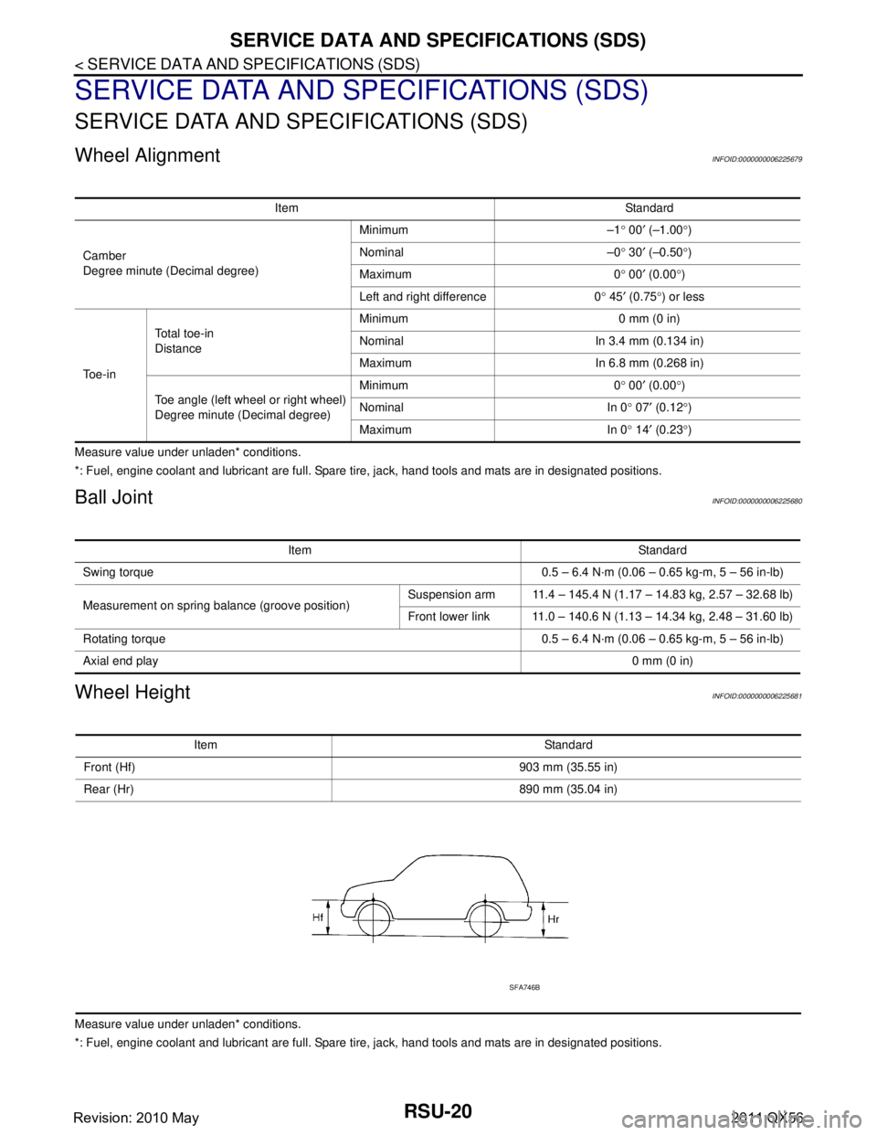
Wheel HeightINFOID:0000000006225681
Measure value under unladen* conditions.
*: Fuel, engine coolant and lubricant are full. Spare tire, jack, hand tools and mats are in designated positions.Item Standard
Camber
Degree minute (Decimal degree) Minimum –1
° 00 ′ (–1.00 °)
Nominal –0 ° 30 ′ (–0.50 °)
Maximum 0 ° 00 ′ (0.00 °)
Left and right difference 0 ° 45 ′ (0.75 °) or less
To e - i n Total toe-in
Distance
Minimum 0 mm (0 in)
Nominal In 3.4 mm (0.134 in)
Maximum In 6.8 mm (0.268 in)
Toe angle (left wheel or right wheel)
Degree minute (Decimal degree) Minimum 0
° 00 ′ (0.00 °)
Nominal In 0 ° 07 ′ (0.12 °)
Maximum In 0 ° 14 ′ (0.23 °)
Item Standard
Swing torque 0.5 – 6.4 N·m (0.06 – 0.65 kg-m, 5 – 56 in-lb)
Measurement on spring balance (groove position) Suspension arm 11.4 – 145.4 N (1.17 – 14.83 kg, 2.57 – 32.68 lb)
Front lower link 11.0 – 140.6 N (1.13 – 14.34 kg, 2.48 – 31.60 lb)
Rotating torque 0.5 – 6.4 N·m (0.06 – 0.65 kg-m, 5 – 56 in-lb)
Axial end play 0 mm (0 in)
Item Standard
Front (Hf) 903 mm (35.55 in)
Rear (Hr) 890 mm (35.04 in)
SFA746B
Revision: 2010 May2011 QX56
Page 4276 of 5598

SB-1
RESTRAINTS
C
DE
F
G
I
J
K L
M
SECTION SB
A
B
SB
N
O P
CONTENTS
SEAT BELT
PRECAUTION ................ ...............................2
PRECAUTIONS .............................................. .....2
Precaution for Supplemental Restraint System
(SRS) "AIR BAG" and "SEAT BELT PRE-TEN-
SIONER" ............................................................. ......
2
Precaution Necessary for Steering Wheel Rota-
tion after Battery Disconnect .....................................
2
Precaution for Seat Belt Service ...............................3
REMOVAL AND INSTALLATION ................4
FRONT SEAT BELT ....................................... .....4
SEAT BELT RETRACTOR .................................... ......4
SEAT BELT RETRACTOR : Inspection ....................4
SEAT BELT RETRACTOR : Exploded View .............6
SEAT BELT RETRACTOR : Removal and Instal-
lation ..........................................................................
6
SEAT BELT BUCKLE ........................................... ......7
SEAT BELT BUCKLE : Inspection ............................7
SEAT BELT BUCKLE : Exploded View .....................8
SEAT BELT BUCKLE : Removal and Installation ......8
SECOND SEAT BELT ........................................10
SEAT BELT RETRACTOR .................................... ....10
SEAT BELT RETRACTOR : Inspection ..................10
SEAT BELT RETRACTOR : Exploded View ...........11
SEAT BELT RETRACTOR : Removal and Instal-
lation ........................................................................
13
SEAT BELT BUCKLE ............................................ ....14
SEAT BELT BUCKLE : Inspection ..........................14
SEAT BELT BUCKLE : Exploded View ...................14
SEAT BELT BUCKLE : Removal and Installation ....16
THIRD SEAT BELT ...........................................17
SEAT BELT RETRACTOR .................................... ....17
SEAT BELT RETRACTOR : Inspection ..................17
SEAT BELT RETRACTOR : Exploded View ...........19
SEAT BELT RETRACTOR : Removal and Instal-
lation ........................................................................
19
SEAT BELT BUCKLE ............................................ ....20
SEAT BELT BUCKLE : Inspection ..........................20
SEAT BELT BUCKLE : Exploded View ...................21
SEAT BELT BUCKLE : Removal and Installation ....21
LATCH SYSTEM FOR CHILDREN ...................22
Exploded View .........................................................22
Removal and Installation .........................................22
Revision: 2010 May2011 QX56
Page 4277 of 5598

SB-2
< PRECAUTION >
PRECAUTIONS
PRECAUTION
PRECAUTIONS
Precaution for Supplemental Restraint System (SRS) "AIR BAG" and "SEAT BELT
PRE-TENSIONER"
INFOID:0000000006369606
The Supplemental Restraint System such as “A IR BAG” and “SEAT BELT PRE-TENSIONER”, used along
with a front seat belt, helps to reduce the risk or severi ty of injury to the driver and front passenger for certain
types of collision. This system includes seat belt switch inputs and dual stage front air bag modules. The SRS
system uses the seat belt switches to determine the front air bag deployment, and may only deploy one front
air bag, depending on the severity of a collision and w hether the front occupants are belted or unbelted.
Information necessary to service the system safely is included in the “SRS AIR BAG” and “SEAT BELT” of this
Service Manual.
WARNING:
• To avoid rendering the SRS inopera tive, which could increase the risk of personal injury or death in
the event of a collision that would result in air bag inflation, all maintenance must be performed by
an authorized NISS AN/INFINITI dealer.
Improper maintenance, including in correct removal and installation of the SRS, can lead to personal
injury caused by unintent ional activation of the system. For re moval of Spiral Cable and Air Bag
Module, see the “SRS AIR BAG”.
Do not use electrical test equipmen t on any circuit related to the SRS unless instructed to in this
Service Manual. SRS wiring harnesses can be identi fied by yellow and/or orange harnesses or har-
ness connectors.
PRECAUTIONS WHEN USING POWER TOOLS (AIR OR ELECTRIC) AND HAMMERS
WARNING:
When working near the Air Bag Diagnosis Sensor Unit or other Air Bag System sensors with the ignition ON or engine running, DO NOT use air or electric power tools or strike near the sensor(s)
with a hammer. Heavy vibration could activate the sensor(s) and deploy the air bag(s), possibly
causing serious injury.
When using air or electric power tools or hammers , always switch the ignition OFF, disconnect the
battery, and wait at least 3 minu tes before performing any service.
Precaution Necessary for Steering W heel Rotation after Battery Disconnect
INFOID:0000000006369607
NOTE:
Before removing and installing any control units, first tu rn the push-button ignition switch to the LOCK posi-
tion, then disconnect bot h battery cables.
After finishing work, confirm that all control unit connectors are connected properly, then re-connect both
battery cables.
Always use CONSULT-III to perform self-diagnosis as a part of each function inspection after finishing work.
If a DTC is detected, perform trouble diagnos is according to self-diagnosis results.
For vehicle with steering lock unit, if the battery is disconnected or discharged, the steering wheel will lock and
cannot be turned.
If turning the steering wheel is required with the bat tery disconnected or discharged, follow the operation pro-
cedure below before starting the repair operation.
OPERATION PROCEDURE
1. Connect both battery cables. NOTE:
Supply power using jumper cables if battery is discharged.
2. Turn the push-button ignition switch to ACC position. (At this time, the steering lock will be released.)
3. Disconnect both battery cables. The steering lock wi ll remain released with both battery cables discon-
nected and the steering wheel can be turned.
4. Perform the necessary repair operation.
Revision: 2010 May2011 QX56
Page 4278 of 5598

PRECAUTIONSSB-3
< PRECAUTION >
C
DE
F
G
I
J
K L
M A
B
SB
N
O P
5. When the repair work is completed, re-connect both battery cables. With the brake pedal released, turn
the push-button ignition switch from ACC position to ON position, then to LOCK position. (The steering
wheel will lock when the push-button ignition switch is turned to LOCK position.)
6. Perform self-diagnosis check of a ll control units using CONSULT-III.
Precaution for Seat Belt ServiceINFOID:0000000006217608
CAUTION:
Before removing the front seat belt pre-tensioner assembly, turn the ignition switch off, disconnect
battery negative terminal and wait at least 3 minutes.
Never use electrical test equipment for front seat belt pre-tensioner connector.
After replacing or reinstalling front seat belt pre-tensioner assembly, or reconnecting front seat belt
pre-tensioner connector, check th e system function. Refer to SRC-14, "
Description".
Never use disassembled buckle or seat belt assembly.
Replace anchor bolts if th ey are deformed or worn out.
Never oil tongue and buckle.
If any component of seat belt assembly is questiona ble, do not repair. Replace the entire seat belt
assembly.
If webbing is cut, frayed or damaged, replace seat belt assembly.
When replacing seat belt assembly, u se a genuine NISSAN seat belt assembly.
AFTER A COLLISION
WARNING:
Inspect all seat belt assemblies including retractors and attached hardware after any collision.
NISSAN recommends that all seat belt assemblies in u se during a collision be replaced unless the col-
lision was minor and the belts show no damage a nd continue to operate properly. Failure to do so
could result in serious personal injury in an accide nt. Seat belt assemblies not in use during a colli-
sion should also be replaced if either damage or im proper operation is noted. Seat belt pre-tensioners
should be replaced even if the seat belts are not in use during a frontal collision in which the air bags
are deployed.
Replace any seat belt assembly (including anchor bolts) if:
The seat belt was in use at the time of a collision (except for minor collisions and the belts, retractors and
buckles show no damage and continue to operate properly).
The seat belt was damaged in an accident (i.e. torn webbing, bent retractor or guide).
The seat belt attaching point was damaged in an accident. Inspect the seat belt attaching area for damage or distortion and repair as necessary before installing a new seat belt assembly.
Anchor bolts are deformed or worn out.
The front seat belt pre-tensioner should be replaced even if the seat belts are not in use during the collision
in which the air bags are deployed.
Revision: 2010 May2011 QX56
Page 4304 of 5598
SYSTEMSBC-7
< SYSTEM DESCRIPTION >
C
DE
F
G
I
J
K L
M A
B
SBC
N
O P
SYSTEM
PRE-CRASH SEAT BELT SYSTEM
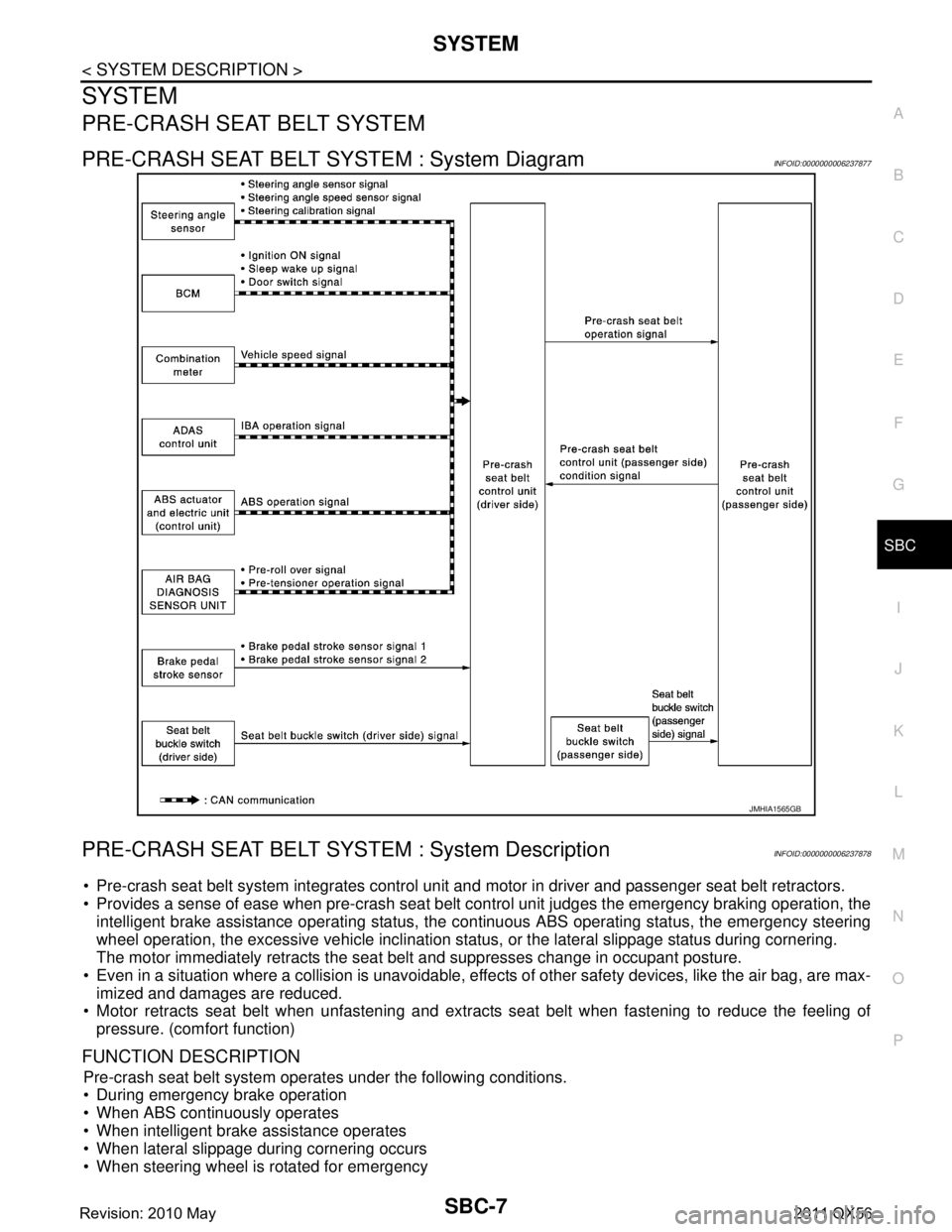
PRE-CRASH SEAT BELT SYSTEM : System DiagramINFOID:0000000006237877
PRE-CRASH SEAT BELT SYSTEM : System DescriptionINFOID:0000000006237878
Pre-crash seat belt system integrates control unit and motor in driver and passenger seat belt retractors.
Provides a sense of ease when pre-crash seat belt c ontrol unit judges the emergency braking operation, the
intelligent brake assistance operating status, the c ontinuous ABS operating status, the emergency steering
wheel operation, the excessive vehicle inclination stat us, or the lateral slippage status during cornering.
The motor immediately retracts the seat belt and suppresses change in occupant posture.
Even in a situation where a collision is unavoidable, effe cts of other safety devices, like the air bag, are max-
imized and damages are reduced.
Motor retracts seat belt when unfastening and extrac ts seat belt when fastening to reduce the feeling of
pressure. (comfort function)
FUNCTION DESCRIPTION
Pre-crash seat belt system operat es under the following conditions.
During emergency brake operation
When ABS continuously operates
When intelligent brake assistance operates
When lateral slippage during cornering occurs
When steering wheel is rotated for emergency
JMHIA1565GB
Revision: 2010 May2011 QX56
Page 4305 of 5598

SBC-8
< SYSTEM DESCRIPTION >
SYSTEM
When the vehicle inclined excessively
When comfort function operates
OPERATION CONDITION
Operation while driving
Operation start and stop conditions of pre-crash seat belt system are as shown in the following table.
The activation and deactivation conditions of pre-crush seat belt are as per the following.
NOTE:
For details of intelligent brake assist system.Refer to BRC-152, "
INTELLIGENT BRAKE ASSIST : System
Description".
Comfort function
Seat belt is retracted and the looseness is reduced in the state as shown in the following table.
Operation start and stop conditions of pre-crash seat belt system are as shown in the following table.
Operation Prohibition Condition
Pre-crash seat belt system does not operate in the following conditions.
When seat belt is not fastened (only the seat belt that is not fastened does not operate)
When motor is overheat due to contentious operation*1
When the system is in fail-safe mode *1: System operation is temporarily deactivated to av oid overheating, when comfort function is continuously
operated (18 times or more) during a short period of time by fastening and unfastening seat belts or opening
and closing doors.
MALFUNCTION WARNING
When system malfunction is detected, comfort function is deactivated to warn customer of system malfunc-
tion.
Operation item Operation start condition Operation stop condition
During emergency brake operation Vehicle speed is 15 km/h (9 MPH) or more
Emergency braking status is detected
During acceleration
When stopped
When ABS continuously operates ABS continuously operates for 2 seconds or
more
Brake pedal is in depressed state
When intelligent brake assistance oper-
ates System detects that intelligent brake assistance is
in operating status
2 seconds after operation start
When lateral slippage during cornering
occurs Vehicle speed is 30 km/h (19 MPH) or more
System detects that the vehicle is in lateral slip-
page state
System detects that the vehicle is driving on a curve Vehicle stopped
1 second or more after maintaining
steering wheel angle in straight driv-
ing state
When steering wheel is rotated for emer-
gency Vehicle speed is 60 km/h (36 MPH) or more
Steering wheel angle is 90 degrees or more
System detects that steering wheel is rotated for
emergency
When the vehicle inclined excessively Vehicle speed is 30 km/h (19 MPH) or more
System detects that the vehicle inclined exces-
sively During acceleration
Vehicle stopped
Operation item Activating condition Deactivating condition
Door open Seat belt is in not fastened state
Door is operated to open from closed
Vehicle stopped Seat belt retract is complete
13 seconds after start retracting
Seat belt is fastened When door is closed
Seat belt is fastened Seat belt is unfastened
1 second after operation
Seat belt is release Seat belt is unfastened Seat belt retract is complete
10 seconds after start retracting
Revision: 2010 May2011 QX56
Page 4306 of 5598

SYSTEMSBC-9
< SYSTEM DESCRIPTION >
C
DE
F
G
I
J
K L
M A
B
SBC
N
O P
PRE-CRASH SEAT BELT SYSTEM : Fail SafeINFOID:0000000006237879
When a system malfunction is detected, deactivates a part of the system or all functions depending on the
malfunctioning part.
When the malfunction condition recovers to the norma l condition, the system returns to the normal opera-
tion.
*1: The deactivation mode differs depending on the internal malfunctioning condition of control unit Display contents of CONSULT-III Fail-safe
U0126 STRG ANG SEN SIG Stops the operation in the conditions as per the following.
When lateral slippage during cornering occurs
When steering wheel is rotated for emergency
A part of comfort function
U0428 STRG ANGL CAL Stops the operation in the conditions as per the following.
When lateral slippage during cornering occurs
When steering wheel is rotated for emergency
A part of comfort function
U1000 CAN communication circuit Stops the operation in the conditions as per the following. *
1
During emergency brake operation
When ABS continuously operates
When lateral slippage during cornering occurs
When Intelligent brake assistance operates
When steering wheel is rotated for emergency
When the vehicle inclined excessively
A part or the whole comfort function
B2451 SEAT BLT MTR DR CIRC Fully deactivates the whole operation.
B2452 SEAT BLT MTR AS CIRC Deactivate s a part of comfort function.
B2453 BR_STROKE_SEN_CIRC Stops the operation in the conditions as per the following.
During emergency brake operation
When ABS continuously operates
A part of comfort function
B2454 SEAT BLT PWR DR CIRC Fully deactivates the whole operation.
B2455 CONTROL UNIT DR Stops the operation in the conditions as per the following. *
1
During emergency brake operation
When ABS continuously operates
When lateral slippage during cornering occurs
When Intelligent brake assistance operates
When steering wheel is rotated for emergency
When the vehicle inclined excessively
A part or the whole comfort function
B2456 SEAT BLT PWR AS Deactivates a part of comfort function.
B2457 CONTROL UNIT AS Deactivates a part of comfort function.
B2458 LOCAL COMM Deactivates a part of comfort function.
B2461 VHCL SPEED SIGNAL Stops the operation in the conditions as per the following.
During emergency brake operation
When ABS continuously operates
When lateral slippage during cornering occurs
When steering wheel is rotated for emergency
When the vehicle inclined excessively
When comfort function operates
B2463 ROLLOVER SIGNAL Stops the operation in the conditions as per the following.
When the vehicle inclined excessively
A part or the whole comfort function
B2466 DR/AS CONTROL UNIT Deactivates a part of comfort function.
B2470 SYS HEAT PROTC DR Fully deactivates the whole operation.
Operation return
- 1 time operation becomes possible after approximately 30 seconds
- Returns to the initial condition after approximately 8 minutes
Revision: 2010 May2011 QX56