wheel INFINITI QX56 2011 Factory Service Manual
[x] Cancel search | Manufacturer: INFINITI, Model Year: 2011, Model line: QX56, Model: INFINITI QX56 2011Pages: 5598, PDF Size: 94.53 MB
Page 5514 of 5598

WT-64
< REMOVAL AND INSTALLATION >
ROAD WHEEL TIRE ASSEMBLY
REMOVAL AND INSTALLATION
ROAD WHEEL TIRE ASSEMBLY
Exploded ViewINFOID:0000000006225547
Removal and InstallationINFOID:0000000006225548
REMOVAL
1. Remove wheel nuts.
2. Remove tire assembly.
INSTALLATION
Note the following, install in the reverse order of removal.
When replacing or rotating wheels, perform the ID registration. Refer to WT-29, "
Work Procedure".
InspectionINFOID:0000000006225549
ALUMINUM WHEEL
1. Check tires for wear and improper inflation.
2. Check wheels for deformation, cracks and other damage. If deformed, remove wheel and check wheel
runout.
a. Remove tire from aluminum wheel and mount on a tire balance machine.
b. Set dial indicator as shown in the figure.
c. Check radial runout, if the latera l deflection (A) or vertical deflec-
tion (B) for radial runout value exceeds the limit, replace alumi-
num wheel.
1. Tire assembly
Refer to GI-4, "
Components" for symbols in the figure.
JPEIC0088GB
Limit
Lateral deflection (A) : Refer to WT-69, "
Road Wheel".
Vertical deflection (B) : Refer to WT-69, "
Road Wheel".
SEIA0737E
Revision: 2010 May2011 QX56
Page 5517 of 5598

TRANSMITTERWT-67
< REMOVAL AND INSTALLATION >
C
DF
G H
I
J
K L
M A
B
WT
N
O P
1. Put first side of tire onto rim.
2. Mount transmitter on rim and tighten nut. CAUTION:
Speed for tightening nut sh ould be less than 10 rpm.
3. Place wheel on turntable of tire machine. Ensure that transmitter (1) is 270 degree from mounting head (2) when second side of
tire is fitted.
NOTE:
Do not touch transmitter at mounting head.
4. Lubricate tire well and fit second side of tire as normal. Ensure that tire does not rotate relative to rim.
5. Inflate tire and fit to appropriate wheel position.
6. Perform the transmitter wake-up after replacing transmitter. Refer to WT-28, "
Work Procedure".
SEIA0049E
JPEIC0014GB
Revision: 2010 May2011 QX56
Page 5518 of 5598

WT-68
< REMOVAL AND INSTALLATION >
TIRE PRESSURE RECEIVER
TIRE PRESSURE RECEIVER
Exploded ViewINFOID:0000000006225554
FRONT TIRE PRESSURE RECEIVER
FRONT TIRE PRESSURE RECEIVER : Removal and InstallationINFOID:0000000006225555
REMOVAL
1. Remove fender protector (rear). Refer to EXT-23, "FENDER PROTECTOR : Removal and Installation".
2. Remove mounting bolt for the front tire pressure receiver.
3. Disconnect front tire pressure receiver harness connector.
4. Remove front tire pressure receiver.
INSTALLATION
Installation is the reverse order of removal.
REAR TIRE PRESSURE RECEIVER
REAR TIRE PRESSURE RECEIVER : Removal and InstallationINFOID:0000000006225556
REMOVAL
1. Remove rear wheel house protector. Refer to EXT-24, "REAR WHEEL HOUSE PROTECTOR : Removal
and Installation".
2. Remove mounting bolt for the rear tire pressure receiver.
3. Disconnect rear tire pressure receiver harness connector.
4. Remove rear tire pressure receiver.
INSTALLATION
Installation is the reverse order of removal.
1. Front tire pressure receiver 2. Rear tire pressure receiver
: Vehicle front
Refer to GI-4, "
Components" for symbols in the figure.
JSEIA0010GB
Revision: 2010 May2011 QX56
Page 5519 of 5598

SERVICE DATA AND SPECIFICATIONS (SDS)
WT-69
< SERVICE DATA AND SPECIFICATIONS (SDS)
C
D F
G H
I
J
K L
M A
B
WT
N
O P
SERVICE DATA AND SPECIFICATIONS (SDS)
SERVICE DATA AND SPECIFICATIONS (SDS)
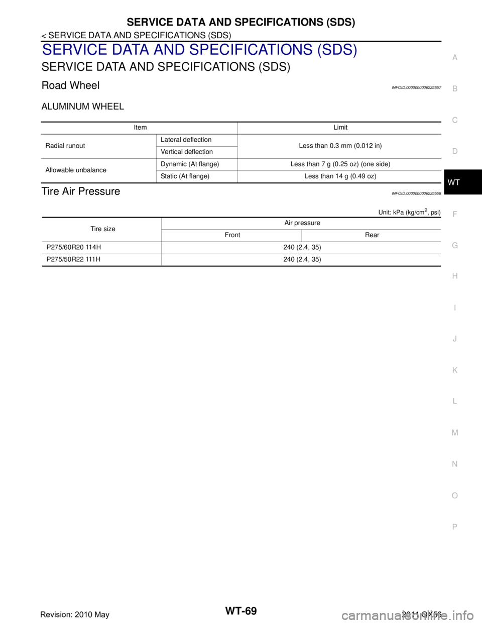
Road WheelINFOID:0000000006225557
ALUMINUM WHEEL
Tire Air PressureINFOID:0000000006225558
Unit: kPa (kg/cm2, psi)
Item Limit
Radial runout Lateral deflection
Less than 0.3 mm (0.012 in)
Vertical deflection
Allowable unbalance Dynamic (At flange) Less than 7 g (0.25 oz) (one side)
Static (At flange) Less than 14 g (0.49 oz)
Tire size Air pressure
Front Rear
P275/60R20 114H 240 (2.4, 35)
P275/50R22 111H 240 (2.4, 35)
Revision: 2010 May2011 QX56
Page 5520 of 5598

WW-1
DRIVER CONTROLS
C
DE
F
G H
I
J
K
M
SECTION WW
A
B
WW
N
O P
CONTENTS
WIPER & WASHER
PRECAUTION ................ ...............................3
PRECAUTIONS .............................................. .....3
Precaution for Supplemental Restraint System
(SRS) "AIR BAG" and "SEAT BELT PRE-TEN-
SIONER" ............................................................. ......
3
Precaution Necessary for Steering Wheel Rota-
tion after Battery Disconnect .....................................
3
Precaution for Procedure without Cowl Top Cover ......4
SYSTEM DESCRIPTION ..............................5
COMPONENT PARTS ................................... .....5
Component Parts Location .................................. ......5
Component Description ............................................6
Washer Switch ..........................................................6
SYSTEM ..............................................................7
FRONT WIPER AND WASHER SYSTEM ............. ......7
FRONT WIPER AND WASHER SYSTEM : Sys-
tem Diagram ..............................................................
7
FRONT WIPER AND WASHER SYSTEM : Sys-
tem Description .........................................................
7
FRONT WIPER AND WASHER SYSTEM : Fail-
safe ...........................................................................
9
REAR WIPER AND WASHER SYSTEM ............... ....10
REAR WIPER AND WASHER SYSTEM : System
Diagram ...................................................................
10
REAR WIPER AND WASHER SYSTEM : System
Description ..............................................................
10
REAR WIPER AND WASHER SYSTEM :
Fail Safe .................................................................
12
HEADLAMP WASHER SYSTEM .......................... ....12
HEADLAMP WASHER SYSTEM : System Dia-
gram ........................................................................
13
HEADLAMP WASHER SYSTEM : System De-
scription ...................................................................
13
DIAGNOSIS SYSTEM (BCM) ............................14
COMMON ITEM ..................................................... ....14
COMMON ITEM : CONSULT-III Function (BCM -
COMMON ITEM) .....................................................
14
WIPER .................................................................... ....15
WIPER : CONSULT-III Function (BCM - WIPER) ....15
DIAGNOSIS SYSTEM (IPDM E/R) ...................18
Diagnosis Description ..............................................18
CONSULT-III Function (IPDM E/R) .........................20
ECU DIAGNOSIS INFORMATION ..............23
BCM, IPDM E/R .................................................23
List of ECU Reference ......................................... ....23
WIRING DIAGRAM ......................................24
WIPER AND WASHER SYSTEM .....................24
Wiring Diagram .................................................... ....24
BASIC INSPECTION ...................................33
DIAGNOSIS AND REPAIR WORKFLOW ........33
Work Flow ............................................................ ....33
DTC/CIRCUIT DIAGNOSIS .........................35
WIPER AND WASHER FUSE ...........................35
Diagnosis Procedure ........................................... ....35
FRONT WIPER MOTOR LO CIRCUIT ..............36
Component Function Check ....................................36
Diagnosis Procedure ...............................................36
FRONT WIPER MOTOR HI CIRCUIT ...............37
Component Function Check ....................................37
Diagnosis Procedure ...............................................37
FRONT WIPER AUTO STOP SIGNAL CIR-
CUIT ..................................................................
38
Component Function Check ....................................38
Diagnosis Procedure ...............................................38
Revision: 2010 May2011 QX56
Page 5522 of 5598

PRECAUTIONSWW-3
< PRECAUTION >
C
DE
F
G H
I
J
K
M A
B
WW
N
O P
PRECAUTION
PRECAUTIONS
Precaution for Supplemental Restraint System (SRS) "AIR BAG" and "SEAT BELT
PRE-TENSIONER"
INFOID:0000000006349780
The Supplemental Restraint System such as “A IR BAG” and “SEAT BELT PRE-TENSIONER”, used along
with a front seat belt, helps to reduce the risk or severi ty of injury to the driver and front passenger for certain
types of collision. This system includes seat belt switch inputs and dual stage front air bag modules. The SRS
system uses the seat belt switches to determine the front air bag deployment, and may only deploy one front
air bag, depending on the severity of a collision and whether the front occupants are belted or unbelted.
Information necessary to service the system safely is included in the “SRS AIR BAG” and “SEAT BELT” of this
Service Manual.
WARNING:
• To avoid rendering the SRS inoper ative, which could increase the risk of personal injury or death in
the event of a collision that would result in air ba g inflation, all maintenance must be performed by
an authorized NISSAN/INFINITI dealer.
Improper maintenance, including in correct removal and installation of the SRS, can lead to personal
injury caused by unintentional act ivation of the system. For removal of Spiral Cable and Air Bag
Module, see the “SRS AIR BAG”.
Do not use electrical test equipm ent on any circuit related to the SRS unless instructed to in this
Service Manual. SRS wiring harnesses can be identi fied by yellow and/or orange harnesses or har-
ness connectors.
PRECAUTIONS WHEN USING POWER TOOLS (AIR OR ELECTRIC) AND HAMMERS
WARNING:
When working near the Air Bag Diagnosis Sensor Unit or other Air Bag System sensors with the
ignition ON or engine running, DO NOT use air or electric power tools or strike near the sensor(s)
with a hammer. Heavy vibration could activate the sensor(s) and deploy the air bag(s), possibly
causing serious injury.
When using air or electric power tools or hammers , always switch the ignition OFF, disconnect the
battery, and wait at least 3 minutes before performing any service.
Precaution Necessary for Steering Wh eel Rotation after Battery Disconnect
INFOID:0000000006300446
NOTE:
Before removing and installing any control units, first tu rn the push-button ignition switch to the LOCK posi-
tion, then disconnect both battery cables.
After finishing work, confirm that all control unit connectors are connected properly, then re-connect both
battery cables.
Always use CONSULT-III to perform self-diagnosis as a part of each function inspection after finishing work.
If a DTC is detected, perform trouble diagnos is according to self-diagnosis results.
For vehicle with steering lock unit, if the battery is disconnected or discharged, the steering wheel will lock and
cannot be turned.
If turning the steering wheel is required with the batte ry disconnected or discharged, follow the operation pro-
cedure below before starting the repair operation.
OPERATION PROCEDURE
1. Connect both battery cables. NOTE:
Supply power using jumper cables if battery is discharged.
2. Turn the push-button ignition switch to ACC position. (At this time, the steering lock will be released.)
3. Disconnect both battery cables. The steering lock wil l remain released with both battery cables discon-
nected and the steering wheel can be turned.
4. Perform the necessary repair operation.
Revision: 2010 May2011 QX56
Page 5523 of 5598

WW-4
< PRECAUTION >
PRECAUTIONS
5. When the repair work is completed, re-connect both battery cables. With the brake pedal released, turn
the push-button ignition switch from ACC position to ON position, then to LOCK position. (The steering
wheel will lock when the push-button igniti on switch is turned to LOCK position.)
6. Perform self-diagnosis check of all control units using CONSULT-III.
Precaution for Procedure without Cowl Top CoverINFOID:0000000006300447
When performing the procedure after removing cowl top cover, cover
the lower end of windshield with urethane, etc.
PIIB3706J
Revision: 2010 May2011 QX56