INFINITI QX56 2011 Factory Service Manual
QX56 2011
INFINITI
INFINITI
https://www.carmanualsonline.info/img/42/57033/w960_57033-0.png
INFINITI QX56 2011 Factory Service Manual
Trending: fog light, roof rack, center console, maintenance, headrest, high pressure fuel pump replacement, buttons
Page 371 of 5598
AV
BOSE AMP.AV-223
< REMOVAL AND INSTALLATION >
C
DE
F
G H
I
J
K L
M B A
O P
BOSE AMP.
Removal and InstallationINFOID:0000000006216389
REMOVAL
1. Remove rear ventilator duct lower. Refer to HA-46, "Exploded View".
2. Remove shield bracket. Refer to SR-24, "
Exploded View".
3. Remove rear drain hose clip. Obtain a service area. Refer to RF-37, "
Exploded View".
4. Remove BOSE amp. mounting bolts.
5. Disconnect BOSE amp. connecto r to remove BOSE amp.
INSTALLATION
Install in the reverse order of removal.
Revision: 2010 May2011 QX56
Page 372 of 5598
AV-224
< REMOVAL AND INSTALLATION >
ANTENNA AMP.
ANTENNA AMP.
Removal and InstallationINFOID:0000000006216390
REMOVAL
1. Remove side curtain air bag module RH. Refer to SR-19, "Exploded View".
2. Remove antenna amp. mounting screw.
3. Disconnect antenna amp. connector to remove antenna amp.
INSTALLATION
Install in the reverse order of removal.
Revision: 2010 May2011 QX56
Page 373 of 5598

AV
SATELLITE RADIO ANTENNAAV-225
< REMOVAL AND INSTALLATION >
C
DE
F
G H
I
J
K L
M B A
O P
SATELLITE RADIO ANTENNA
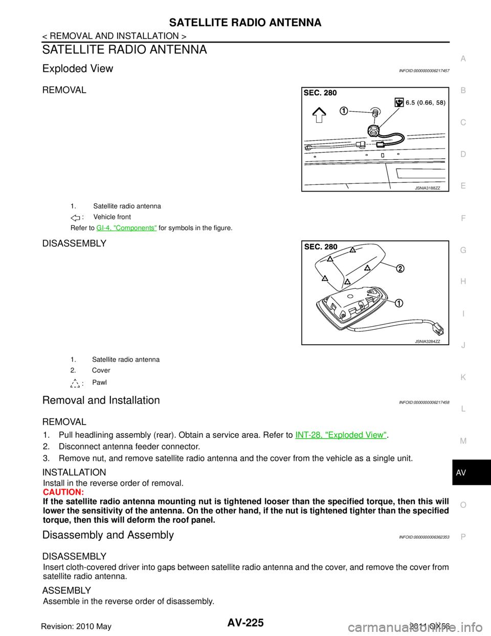
Exploded ViewINFOID:0000000006217457
REMOVAL
DISASSEMBLY
Removal and InstallationINFOID:0000000006217458
REMOVAL
1. Pull headlining assembly (rear). Obtain a service area. Refer to INT-28, "Exploded View".
2. Disconnect antenna feeder connector.
3. Remove nut, and remove satellite radio antenna and the cover from the vehicle as a single unit.
INSTALLATION
Install in the reverse order of removal.
CAUTION:
If the satellite radio ante nna mounting nut is tightened looser than the specified torque, then this will
lower the sensitivity of the antenna. On the other hand, if the nut is tightened tighter than the specified
torque, then this will deform the roof panel.
Disassembly and AssemblyINFOID:0000000006362353
DISASSEMBLY
Insert cloth-covered driver into gaps between satel lite radio antenna and the cover, and remove the cover from
satellite radio antenna.
ASSEMBLY
Assemble in the reverse order of disassembly.
JSNIA3188ZZ
1. Satellite radio antenna
: Vehicle front
Refer to GI-4, "
Components" for symbols in the figure.
JSNIA3284ZZ
1. Satellite radio antenna
2. Cover
: Pawl
Revision: 2010 May2011 QX56
Page 374 of 5598
AV-226
< REMOVAL AND INSTALLATION >
MULTIFUNCTION SWITCH
MULTIFUNCTION SWITCH
Removal and InstallationINFOID:0000000006216391
REMOVAL
1. Remove cluster lid C. Refer to IP-13, "Exploded View".
2. Disconnect multifunction switch connector.
3. Remove multifunction switch mounting screws to remove multifunction switch from cluster lid C.
INSTALLATION
Install in the reverse order of removal.
Revision: 2010 May2011 QX56
Page 375 of 5598
AV
PRESET SWITCHAV-227
< REMOVAL AND INSTALLATION >
C
DE
F
G H
I
J
K L
M B A
O P
PRESET SWITCH
Removal and InstallationINFOID:0000000006216392
REMOVAL
1. Remove cluster lid C. Refer to IP-13, "Exploded View".
2. Disconnect preset switch (1) connector.
3. Remove preset switch mounting screws (A) and (B).
4. Remove preset switch from cluster lid C.
INSTALLATION
Install in the reverse order of removal.
JSNIA2983ZZ
Revision: 2010 May2011 QX56
Page 376 of 5598
AV-228
< REMOVAL AND INSTALLATION >
FRONT AUXILIARY INPUT JACKS
FRONT AUXILIARY INPUT JACKS
Removal and InstallationINFOID:0000000006216393
REMOVAL
1. Remove center console assembly. Refer to IP-23, "Exploded View".
2. Remove front auxiliary input jacks mounting sc rews to remove front auxiliary input jacks.
INSTALLATION
Install in the reverse order of removal.
Revision: 2010 May2011 QX56
Page 377 of 5598
AV
REAR AUXILIARY INPUT JACKSAV-229
< REMOVAL AND INSTALLATION >
C
DE
F
G H
I
J
K L
M B A
O P
REAR AUXILIARY INPUT JACKS
Removal and InstallationINFOID:0000000006216394
REMOVAL
1. Remove console rear finisher. Refer to IP-23, "Exploded View".
2. Remove rear auxiliary input jacks mounting scr ews to remove rear auxiliary input jacks.
INSTALLATION
Install in the reverse order of removal.
Revision: 2010 May2011 QX56
Page 378 of 5598
AV-230
< REMOVAL AND INSTALLATION >
USB CONNECTOR
USB CONNECTOR
Removal and InstallationINFOID:0000000006216395
REMOVAL
1. Remove console finisher assembly. Refer to IP-23, "Exploded View".
2. Press the pawl from the back of console finisher assembly to remove USB connector.
INSTALLATION
Install in the reverse order of removal.
Revision: 2010 May2011 QX56
Page 379 of 5598
AV
MICROPHONEAV-231
< REMOVAL AND INSTALLATION >
C
DE
F
G H
I
J
K L
M B A
O P
MICROPHONE
Removal and InstallationINFOID:0000000006216396
REMOVAL
1. Remove map lamp assembly. Refer to INT-28, "Exploded View".
2. Remove microphone, stretching pawls of roof console assembly.
INSTALLATION
Install in the reverse order of removal.
Revision: 2010 May2011 QX56
Page 380 of 5598
AV-232
< REMOVAL AND INSTALLATION >
GPS ANTENNA
GPS ANTENNA
Removal and InstallationINFOID:0000000006216397
REMOVAL
1. Remove instrument panel. Refer to IP-13, "Exploded View".
2. Remove GPS antenna feeder clips.
3. Remove GPS antenna mounting screws to remove GPS antenna.
INSTALLATION
Install in the reverse order of removal.
Revision: 2010 May2011 QX56
Trending: transmission fluid, differential, bluetooth, USB, compression ratio, remote start, gas type


