wheel torque INFINITI QX56 2011 Factory Workshop Manual
[x] Cancel search | Manufacturer: INFINITI, Model Year: 2011, Model line: QX56, Model: INFINITI QX56 2011Pages: 5598, PDF Size: 94.53 MB
Page 4989 of 5598

ST-2
STEERING WHEEL ...........................................33
Exploded View ..................................................... ...33
Removal and Installation ........................................33
STEERING COLUMN ........................................34
Exploded View ..................................................... ...34
Removal and Installation ........................................34
Inspection ...............................................................35
STEERING SHAFT ............................................37
Exploded View ..................................................... ...37
Removal and Installation ........................................37
Inspection ...............................................................39
STEERING GEAR AND LINKAGE ....................41
Exploded View ..................................................... ...41
Removal and Installation ........................................42
Disassembly and Assembly ....................................43
Inspection ...............................................................46
POWER STEERING OIL PUMP ........................48
Exploded View ..................................................... ...48
Removal and Installation ........................................49
Disassembly and Assembly ....................................50
Inspection ...............................................................52
HYDRAULIC LINE .......................................... ...54
Exploded View ..................................................... ...54
HEATED STEERING WHEEL SWITCH ............56
Exploded View ..................................................... ...56
Removal and Installation .........................................56
SERVICE DATA AND SPECIFICATIONS
(SDS) .......... ................................................
57
SERVICE DATA AND SPECIFICATIONS
(SDS) .............................................................. ...
57
General Specifications ......................................... ...57
Steering Wheel Axial End Play and Play ................57
Steering Wheel Turning Force ................................57
Steering Angle ........................................................57
Steering Column Length .........................................57
Steering Column Mounting Dimensions ..................57
Steering Column Operating Range .........................57
Steering Shaft Sliding Range ..................................58
Rack Sliding Force ..................................................58
Rack Stroke ............................................................58
Socket Swing Force and Rotating Torque ..............58
Socket Axial End Play .............................................58
Inner Socket Length ................................................58
Relief Oil Pressure ..................................................58
Revision: 2010 May2011 QX56
Page 4992 of 5598
PREPARATIONST-5
< PREPARATION >
C
DE
F
H I
J
K L
M A
B
ST
N
O P
PREPARATION
PREPARATION
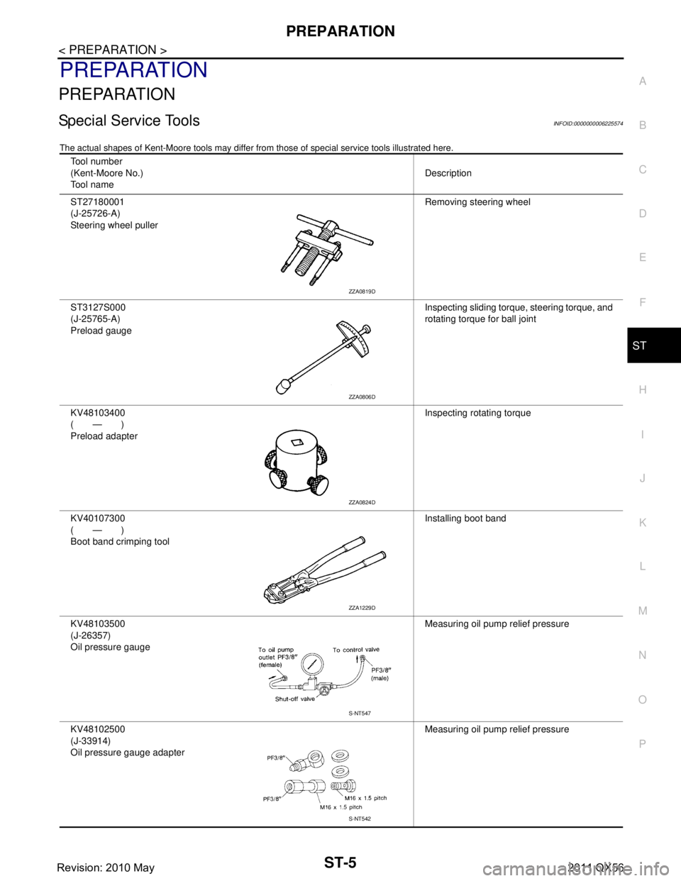
Special Service ToolsINFOID:0000000006225574
The actual shapes of Kent-Moore t ools may differ from those of special service tools illustrated here.
Tool number
(Kent-Moore No.)
Tool name Description
ST27180001
(J-25726-A)
Steering wheel puller Removing steering wheel
ST3127S000
(J-25765-A)
Preload gauge Inspecting sliding torque, steering torque, and
rotating torque for ball joint
KV48103400
(—)
Preload adapter Inspecting rotating torque
KV40107300
(—)
Boot band crimping tool Installing boot band
KV48103500
(J-26357)
Oil pressure gauge Measuring oil pump relief pressure
KV48102500
(J-33914)
Oil pressure gauge adapter Measuring oil pump relief pressure
ZZA0819D
ZZA0806D
ZZA0824D
ZZA1229D
S-NT547
S-NT542
Revision: 2010 May2011 QX56
Page 5016 of 5598
NOISE, VIBRATION AND HARSHNESS (NVH) TROUBLESHOOTINGST-29
< SYMPTOM DIAGNOSIS >
C
DE
F
H I
J
K L
M A
B
ST
N
O P
NOISE, VIBRATION AND HARSHN ESS (NVH) TROUBLESHOOTING
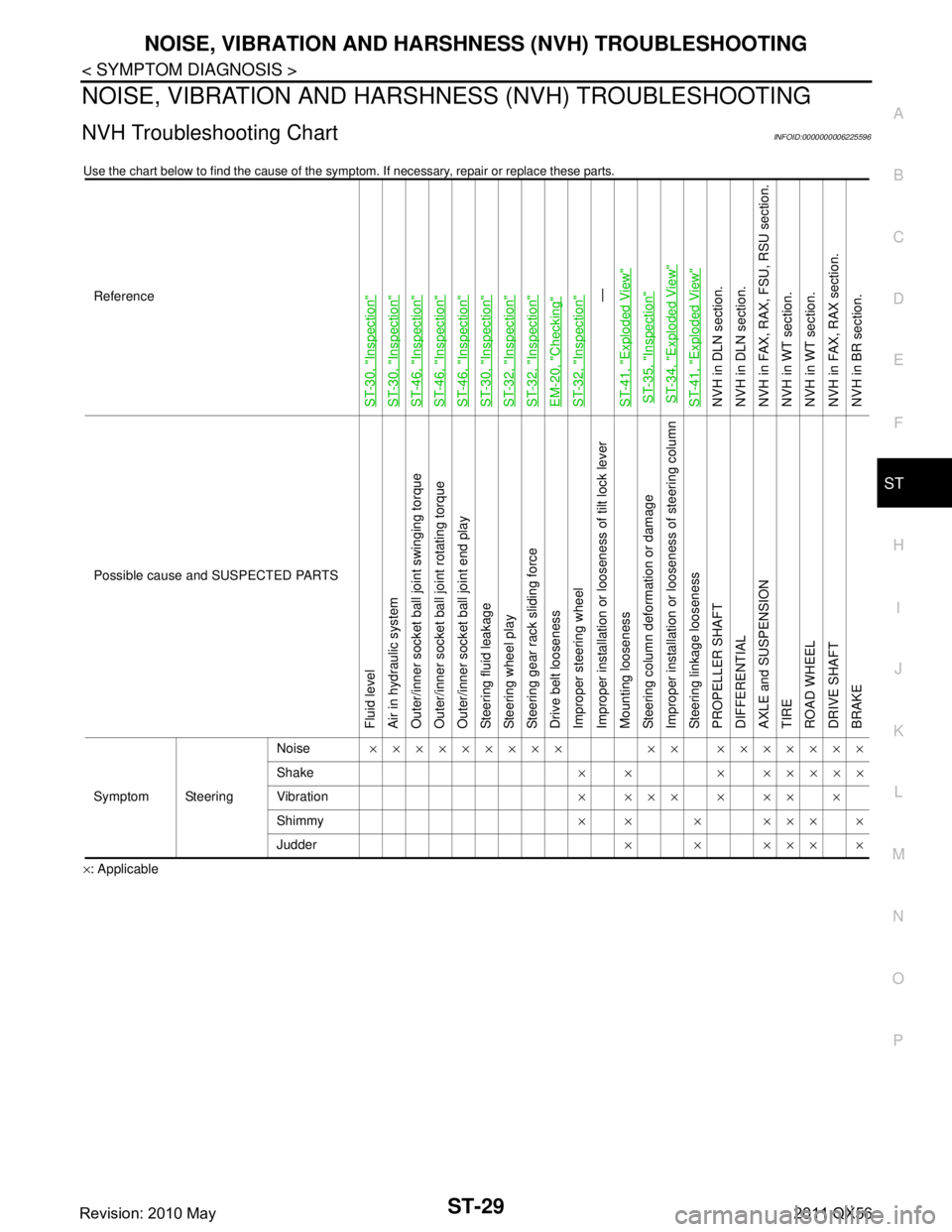
NVH Troubleshooting ChartINFOID:0000000006225596
Use the chart below to find the cause of the symp tom. If necessary, repair or replace these parts.
×: ApplicableReference
ST-30, "
Inspection
"
ST-30, "
Inspection
"
ST-46, "
Inspection
"
ST-46, "
Inspection
"
ST-46, "
Inspection
"
ST-30, "
Inspection
"
ST-32, "
Inspection
"
ST-32, "
Inspection
"
EM-20, "
Checking
"
ST-32, "
Inspection
"—
ST-41, "
Exploded View
"
ST-35, "
Inspection
"
ST-34, "
Exploded View
"
ST-41, "
Exploded View
"
NVH in DLN section.
NVH in DLN section.
NVH in FAX, RAX, FSU, RSU section.
NVH in WT section.
NVH in WT section.
NVH in FAX, RAX section.
NVH in BR section.
Possible cause and SUSPECTED PARTS
Fluid level
Air in hydraulic system
Outer/inner socket ball joint swinging torque
Outer/inner socket ball joint rotating torque
Outer/inner socket ball joint end play
Steering fluid leakage
Steering wheel play
Steering gear rack sliding force
Drive belt looseness
Improper steering wheel
Improper installation or looseness of tilt lock lever
Mounting looseness
Steering column deformation or damage
Improper installation or looseness of steering column
Steering linkage looseness
PROPELLER SHAFT
DIFFERENTIAL
AXLE and SUSPENSION
TIRE
ROAD WHEEL
DRIVE SHAFT
BRAKE
Symptom Steering Noise
××××××××× ×× ×××××××
Shake × × × ×××××
Vibration ××××××××
Shimmy ×× × ××××
Judder ××××××
Revision: 2010 May2011 QX56
Page 5025 of 5598
ST-38
< REMOVAL AND INSTALLATION >
STEERING SHAFT
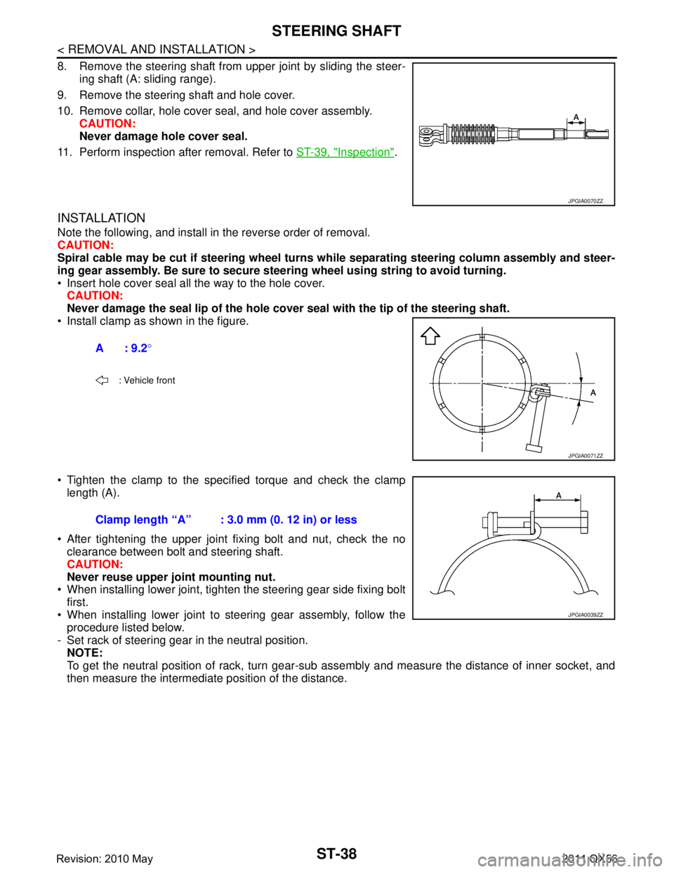
8. Remove the steering shaft from upper joint by sliding the steer-ing shaft (A: sliding range).
9. Remove the steering shaft and hole cover.
10. Remove collar, hole cover seal, and hole cover assembly. CAUTION:
Never damage hole cover seal.
11. Perform inspection after removal. Refer to ST-39, "
Inspection".
INSTALLATION
Note the following, and install in the reverse order of removal.
CAUTION:
Spiral cable may be cut if steering wheel turns while separating steering column assembly and steer-
ing gear assembly. Be sure to secure steer ing wheel using string to avoid turning.
Insert hole cover seal all the way to the hole cover. CAUTION:
Never damage the seal lip of the hole cover seal with the tip of the steering shaft.
Install clamp as shown in the figure.
Tighten the clamp to the spec ified torque and check the clamp
length (A).
After tightening the upper joint fixing bolt and nut, check the no clearance between bolt and steering shaft.
CAUTION:
Never reuse upper joint mounting nut.
When installing lower joint, tighten the steering gear side fixing bolt
first.
When installing lower joint to steering gear assembly, follow the procedure listed below.
- Set rack of steering gear in the neutral position. NOTE:
To get the neutral position of rack, turn gear-sub as sembly and measure the distance of inner socket, and
then measure the intermediate position of the distance.
JPGIA0070ZZ
A: 9.2 °
: Vehicle front
JPGIA0071ZZ
Clamp length “A” : 3.0 mm (0. 12 in) or less
JPGIA0039ZZ
Revision: 2010 May2011 QX56
Page 5034 of 5598
STEERING GEAR AND LINKAGEST-47
< REMOVAL AND INSTALLATION >
C
DE
F
H I
J
K L
M A
B
ST
N
O P
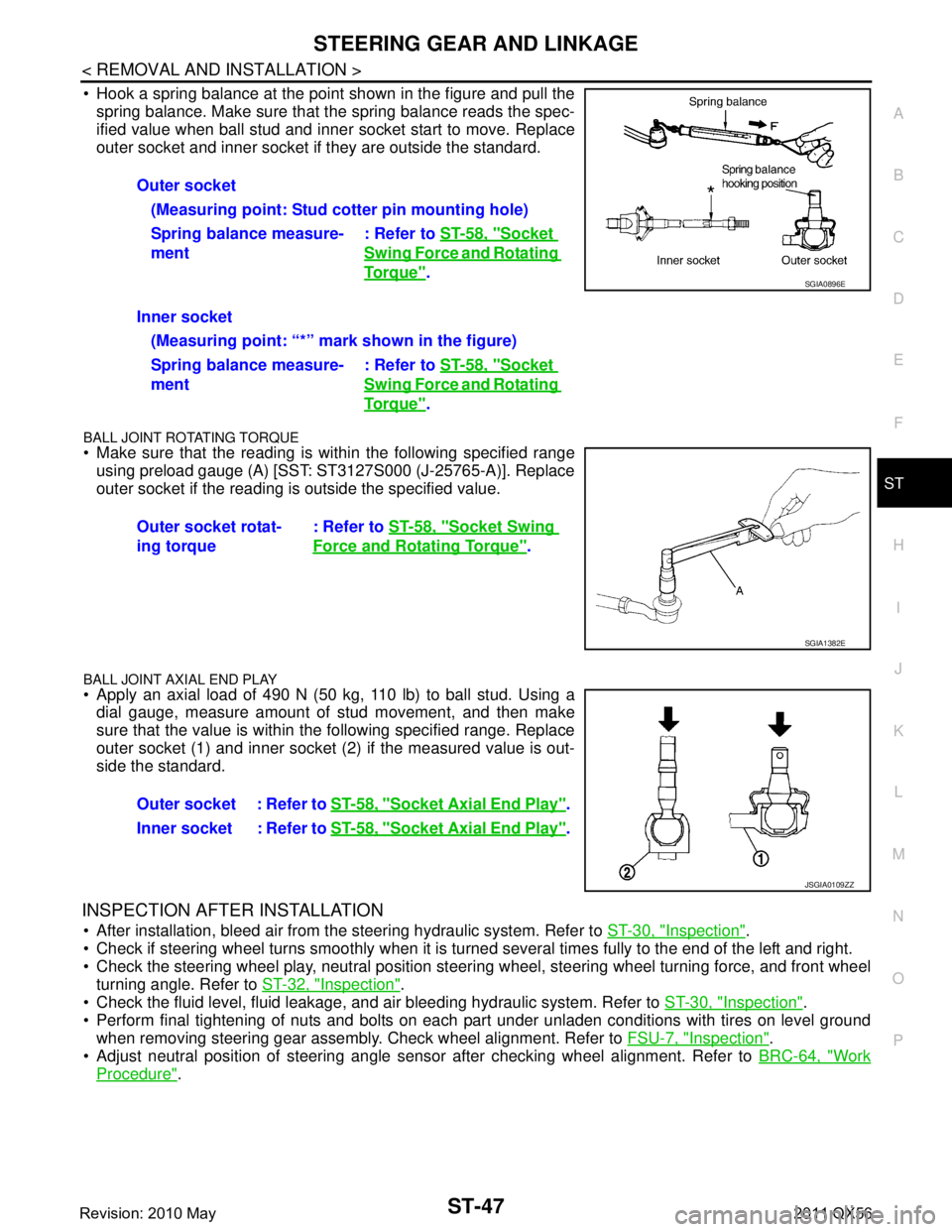
Hook a spring balance at the point shown in the figure and pull the spring balance. Make sure that the spring balance reads the spec-
ified value when ball stud and inner socket start to move. Replace
outer socket and inner socket if they are outside the standard.
BALL JOINT ROTATING TORQUE
Make sure that the reading is within the following specified rangeusing preload gauge (A) [SST: ST3127S000 (J-25765-A)]. Replace
outer socket if the reading is outside the specified value.
BALL JOINT AXIAL END PLAY
Apply an axial load of 490 N (50 kg, 110 lb) to ball stud. Using adial gauge, measure amount of stud movement, and then make
sure that the value is within the following specified range. Replace
outer socket (1) and inner socket (2) if the measured value is out-
side the standard.
INSPECTION AFTER INSTALLATION
After installation, bleed air from the steering hydraulic system. Refer to ST-30, "Inspection".
Check if steering wheel turns smoothly when it is turned several times fully to the end of the left and right.
Check the steering wheel play, neutral position steeri ng wheel, steering wheel turning force, and front wheel
turning angle. Refer to ST-32, "
Inspection".
Check the fluid level, fluid leakage, and air bleeding hydraulic system. Refer to ST-30, "
Inspection".
Perform final tightening of nuts and bolts on each part under unladen conditions with tires on level ground when removing steering gear assembly. Check wheel alignment. Refer to FSU-7, "
Inspection".
Adjust neutral position of steering angle sensor after checking wheel alignment. Refer to BRC-64, "
Work
Procedure".
Outer socket
(Measuring point: Stud cotter pin mounting hole)
Spring balance measure-
ment : Refer to
ST-58, "
Socket
Swing Force and Rotating
To r q u e".
Inner socket (Measuring point: “*” mark shown in the figure)
Spring balance measure-
ment : Refer to
ST-58, "
Socket
Swing Force and Rotating
To r q u e".
Outer socket rotat-
ing torque : Refer to
ST-58, "
Socket Swing
Force and Rotating Torque".
SGIA0896E
SGIA1382E
Outer socket : Refer to ST-58, "Socket Axial End Play".
Inner socket : Refer to ST-58, "
Socket Axial End Play".
JSGIA0109ZZ
Revision: 2010 May2011 QX56
Page 5044 of 5598
SERVICE DATA AND SPECIFICATIONS (SDS)
ST-57
< SERVICE DATA AND SPECIFICATIONS (SDS)
C
D E
F
H I
J
K L
M A
B
ST
N
O P
SERVICE DATA AND SPECIFICATIONS (SDS)
SERVICE DATA AND SPECIFICATIONS (SDS)
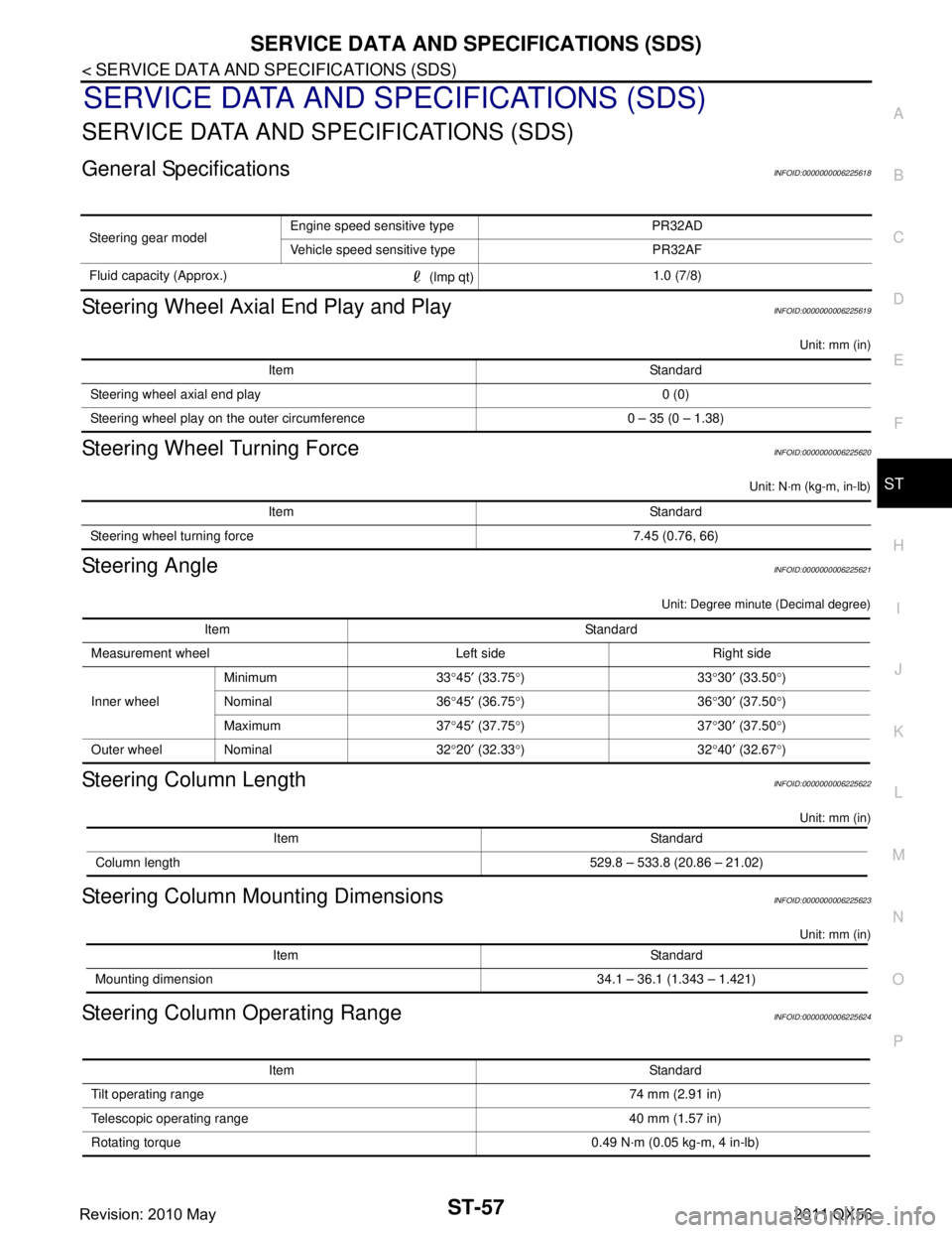
General SpecificationsINFOID:0000000006225618
Steering Wheel Axial End Play and PlayINFOID:0000000006225619
Unit: mm (in)
Steering Wheel Turning ForceINFOID:0000000006225620
Unit: N·m (kg-m, in-lb)
Steering AngleINFOID:0000000006225621
Unit: Degree minute (Decimal degree)
Steering Column LengthINFOID:0000000006225622
Unit: mm (in)
Steering Column Mounting DimensionsINFOID:0000000006225623
Unit: mm (in)
Steering Column Operating RangeINFOID:0000000006225624
Steering gear model Engine speed sensitive type PR32AD
Vehicle speed sensitive type PR32AF
Fluid capacity (Approx.) (lmp qt)1.0 (7/8)
Item Standard
Steering wheel axial end play 0 (0)
Steering wheel play on the outer circumference 0 – 35 (0 – 1.38)
Item Standard
Steering wheel turning force 7.45 (0.76, 66)
Item Standard
Measurement wheel Left side Right side
Inner wheel Minimum 33
°45 ′ (33.75 °)33 °30 ′ (33.50 °)
Nominal 36 °45 ′ (36.75 °)36 °30 ′ (37.50 °)
Maximum 37 °45 ′ (37.75 °)37 °30 ′ (37.50 °)
Outer wheel Nominal 32 °20 ′ (32.33 °)32 °40 ′ (32.67 °)
Item Standard
Column length 529.8 – 533.8 (20.86 – 21.02)
Item Standard
Mounting dimension 34.1 – 36.1 (1.343 – 1.421)
Item Standard
Tilt operating range 74 mm (2.91 in)
Telescopic operating range 40 mm (1.57 in)
Rotating torque 0.49 N· m (0.05 kg-m, 4 in-lb)
Revision: 2010 May2011 QX56
Page 5046 of 5598

STC-1
STEERING
C
DE
F
H I
J
K L
M
SECTION STC
A
B
STC
N
O P
CONTENTS
STEERING CONTROL SYSTEM
PRECAUTION ................ ...............................2
PRECAUTIONS .............................................. .....2
Precaution for Supplemental Restraint System
(SRS) "AIR BAG" and "SEAT BELT PRE-TEN-
SIONER" ............................................................. ......
2
Precaution Necessary for Steering Wheel Rota-
tion after Battery Disconnect .....................................
2
SYSTEM DESCRIPTION ..............................4
COMPONENT PARTS ................................... .....4
Component Parts Location .................................. ......4
Component Description .............................................4
Power Steering Control Unit ......................................4
Power Steering Solenoid Valve .................................4
SYSTEM ..............................................................5
EPS SYSTEM ........................................ ......................5
EPS SYSTEM : System De scription .........................5
EPS SYSTEM : Fail-Safe ..........................................6
ECU DIAGNOSIS INFO RMATION ...............8
POWER STEERING CONTROL UNIT ........... .....8
Reference Value ................................................. ......8
Fail-Safe ....................................................................9
WIRING DIAGRAM ......................................10
ELECTRONICALLY CONTROLLED POWER
STEERING SYSTEM ...................................... ....
10
Wiring Diagram ................................................... ....10
BASIC INSPECTION ...................................13
DIAGNOSIS AND REPAIR WORK FLOW .......13
Work Flow ............................................................ ....13
DTC/CIRCUIT DIAGNOSIS .........................14
POWER SUPPLY AND GROUND CIRCUIT ....14
Diagnosis Procedure ........................................... ....14
POWER STEERING SOLENOID VALVE .........16
Component Function Check ....................................16
Diagnosis Procedure ...............................................16
Component Inspection .............................................17
ENGINE SPEED SIGNAL CIRCUIT ..................18
Diagnosis Procedure ........................................... ....18
VEHICLE SPEED SIGNAL CIRCUIT ................20
Diagnosis Procedure ...............................................20
SYMPTOM DIAGNOSIS ..............................22
UNBALANCE STEERING WHEEL TURNING
FORCE (TORQUE VARIATION) .......................
22
Description ........................................................... ....22
Diagnosis Procedure ...............................................22
REMOVAL AND INSTALLATION ...............23
POWER STEERING CONTROL UNIT ..............23
Removal and Installation ..................................... ....23
Revision: 2010 May2011 QX56
Page 5051 of 5598
STC-6
< SYSTEM DESCRIPTION >
SYSTEM
OPERATION PRINCIPLE
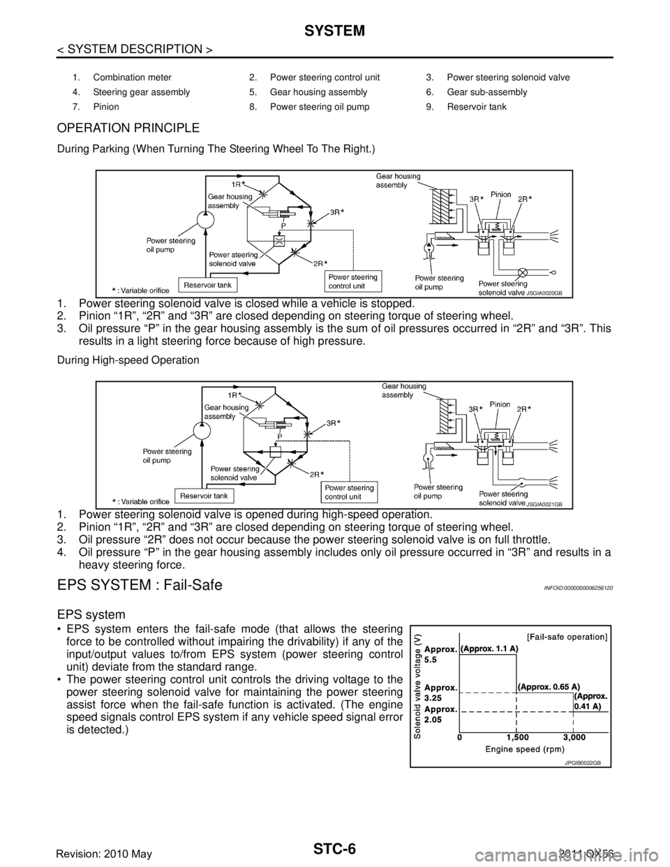
During Parking (When Turning The Steering Wheel To The Right.)
1. Power steering solenoid valve is closed while a vehicle is stopped.
2. Pinion “1R”, “2R” and “3R” are closed depending on steering torque of steering wheel.
3. Oil pressure “P” in the gear housing assembly is the sum of oil pressures occurred in “2R” and “3R”. Thisresults in a light steering force because of high pressure.
During High-speed Operation
1. Power steering solenoid valve is opened during high-speed operation.
2. Pinion “1R”, “2R” and “3R” are closed depending on steering torque of steering wheel.
3. Oil pressure “2R” does not occur because the pow er steering solenoid valve is on full throttle.
4. Oil pressure “P” in the gear housing assembly includes only oil pressure occurred in “3R” and results in a heavy steering force.
EPS SYSTEM : Fail-Safe INFOID:0000000006256120
EPS system
EPS system enters the fail-safe mode (that allows the steering
force to be controlled without impairi ng the drivability) if any of the
input/output values to/from EPS system (power steering control
unit) deviate from the standard range.
The power steering control unit controls the driving voltage to the
power steering solenoid valve for maintaining the power steering
assist force when the fail-safe function is activated. (The engine
speed signals control EPS system if any vehicle speed signal error
is detected.)
1. Combination meter 2. Power steering control unit 3. Power steering solenoid valve
4. Steering gear assembly 5. Gear housing assembly 6. Gear sub-assembly
7. Pinion 8. Power steering oil pump 9. Reservoir tank
JSGIA0020GB
JSGIA0021GB
JPGIB0022GB
Revision: 2010 May2011 QX56
Page 5067 of 5598
STC-22
< SYMPTOM DIAGNOSIS >
UNBALANCE STEERING WHEEL TURNING FORCE (TORQUE VARIATION)
SYMPTOM DIAGNOSIS
UNBALANCE STEERING WHEEL TURNING FORCE (TORQUE VARIA-
TION)
Description INFOID:0000000006256131
Hard steering when fully turning the steering wheel.
Light steering when driving at a high speed.
Diagnosis Procedure INFOID:0000000006256132
1.CHECK SYSTEM FOR POWER SUPPLY AND GROUND
Perform trouble diagnosis for power supply and ground. Refer to STC-14, "
Diagnosis Procedure".
Is the inspection result normal?
YES >> GO TO 2.
NO >> Repair or replace error-detected parts.
2.CHECK SYSTEM FOR VEHICLE SPEED SIGNAL
Perform trouble diagnosis for vehicle speed signal. Refer to STC-20, "
Diagnosis Procedure".
Is the inspection result normal?
YES >> GO TO 3.
NO >> Repair or replace error-detected parts.
3.CHECK SYSTEM FOR ENGINE SPEED SIGNAL
Perform trouble diagnosis for engine speed signal. Refer to STC-18, "
Diagnosis Procedure".
Is the inspection result normal?
YES >> GO TO 4.
NO >> Repair or replace error-detected parts.
4.CHECK SYSTEM FOR POWER STEERING SOLENOID VALVE
Perform trouble diagnosis for power steering solenoid valve. Refer to STC-16, "
Diagnosis Procedure".
Is the inspection result normal?
YES >> Perform the symptom diagnosis for the steering system. Refer to ST-29, "NVH Troubleshooting
Chart".
NO >> Repair or replace error-detected parts.
Revision: 2010 May2011 QX56
Page 5513 of 5598
ROAD WHEELWT-63
< PERIODIC MAINTENANCE >
C
DF
G H
I
J
K L
M A
B
WT
N
O P
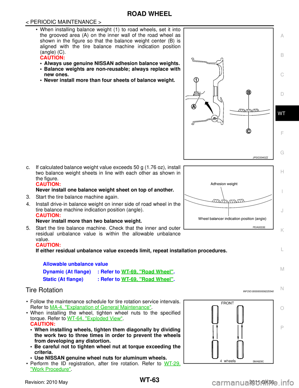
When installing balance weight (1) to road wheels, set it into the grooved area (A) on the inner wall of the road wheel as
shown in the figure so that the balance weight center (B) is
aligned with the tire balance machine indication position
(angle) (C).
CAUTION:
Always use genuine NISSAN ad hesion balance weights.
Balance weights are non-re usable; always replace with
new ones.
Never install more than four sheets of balance weight.
c. If calculated balance weight value exceeds 50 g (1.76 oz), install two balance weight sheets in line with each other as shown in
the figure.
CAUTION:
Never install one balance weight sheet on top of another.
3. Start the tire balance machine again.
4. Install drive-in balance weight on inner side of road wheel in the tire balance machine indication position (angle).
CAUTION:
Never install more than two balance weight.
5. Start the tire balance machine. Check that the inner and outer residual unbalance value is within the allowable unbalance
value.
CAUTION:
If either residual unbalan ce value exceeds limit, repeat installation procedures.
Tire RotationINFOID:0000000006225546
Follow the maintenance schedule for tire rotation service intervals.
Refer to MA-4, "
Explanation of General Maintenance".
When installing the wheel, tighten wheel nuts to the specified torque. Refer to WT-64, "
Exploded View".
CAUTION:
When installing wheels, tighte n them diagonally by dividing
the work two to three times in order to prevent the wheels
from developing any distortion.
Be careful not to tighten wh eel nut at torque exceeding the
criteria.
Use NISSAN genuine wheel nuts for aluminum wheels.
Perform the ID registration, after tire rotation. Refer to WT-29,
"Work Procedure".
JPEIC0040ZZ
Allowable unbalance value
Dynamic (At flange) : Refer to WT-69, "
Road Wheel".
Static (At flange) : Refer to WT-69, "
Road Wheel".
PEIA0033E
SMA829C
Revision: 2010 May2011 QX56