fuel injector INFINITI QX56 2011 Factory Workshop Manual
[x] Cancel search | Manufacturer: INFINITI, Model Year: 2011, Model line: QX56, Model: INFINITI QX56 2011Pages: 5598, PDF Size: 94.53 MB
Page 2610 of 5598
EM-48
< REMOVAL AND INSTALLATION >
FUEL INJECTOR AND FUEL TUBE
FUEL INJECTOR AND FUEL TUBE
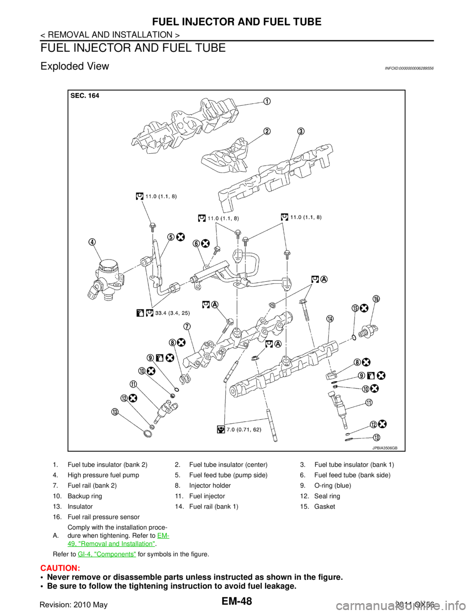
Exploded ViewINFOID:0000000006289556
CAUTION:
Never remove or disassemble parts unless instructed as shown in the figure.
Be sure to follow the tightening instruction to avoid fuel leakage.
1. Fuel tube insulator (bank 2) 2. Fuel tube insulator (center) 3. Fuel tube insulator (bank 1)
4. High pressure fuel pump 5. Fuel feed tube (pump side) 6. Fuel feed tube (bank side)
7. Fuel rail (bank 2) 8. Injector holder 9. O-ring (blue)
10. Backup ring 11. Fuel injector 12. Seal ring
13. Insulator 14. Fuel rail (bank 1) 15. Gasket
16. Fuel rail pressure sensor
A.Comply with the installation proce-
dure when tightening. Refer to
EM-
49, "Removal and Installation".
Refer to GI-4, "
Components" for symbols in the figure.
JPBIA3506GB
Revision: 2010 May2011 QX56
Page 2611 of 5598

FUEL INJECTOR AND FUEL TUBEEM-49
< REMOVAL AND INSTALLATION >
C
DE
F
G H
I
J
K L
M A
EM
NP
O
Removal and InstallationINFOID:0000000006289557
REMOVAL
WARNING:
Be sure to read
EM-4, "
Precaution for Handling High Pressure Fuel System" when working on the
high pressure fuel system.
Put a “CAUTION: FLAMMABLE” sign in the workshop.
Be sure to work in a well ventila ted area and furnish workshop with a CO
2 fire extinguisher.
Never smoke while servicing fuel system. Keep op en flames and sparks away from the work area.
To avoid the danger of being scalded, never drain engine coolant when engine is hot.
1. Release fuel pressure. Refer to EC-153, "
Work Procedure".
2. Remove intake manifold. Refer to EM-30, "
Removal and Installation".
3. Remove fuel feed tube (pump side) and fuel feed tube (bank side). CAUTION:
Never reuse fuel feed tube.
4. Remove fuel rail (bank 1) and fuel rail (bank 2).
5. Disconnect harness connector from fuel injectors.
6. Remove fuel injector from cylinder head as per the following: CAUTION:
Be careful with remaining fuel th at may go out from fuel tube.
Be careful not to damage in jector nozzles during removal.
Never bump or drop fuel injector.
Never disassemble fuel injector.
a. Remove injector holder.
b. Install an injector remover [SST: KV10119600 (—)] (A) to the injector connector side so that cutout (B) of injector remover
faces the injector connector side.
Hook pawl portion (B) of injector remover [SST: KV10119600(—)] (A) to groove portion (C) of injector.
JSBIA0342ZZ
JSBIA0343ZZ
Revision: 2010 May2011 QX56
Page 2612 of 5598
![INFINITI QX56 2011 Factory Workshop Manual
EM-50
< REMOVAL AND INSTALLATION >
FUEL INJECTOR AND FUEL TUBE
c. Press down body portion (A) of injector remover [SST:KV10119600 (—)] until it contacts cylinder head.
d. Tighten injector remover INFINITI QX56 2011 Factory Workshop Manual
EM-50
< REMOVAL AND INSTALLATION >
FUEL INJECTOR AND FUEL TUBE
c. Press down body portion (A) of injector remover [SST:KV10119600 (—)] until it contacts cylinder head.
d. Tighten injector remover](/img/42/57033/w960_57033-2611.png)
EM-50
< REMOVAL AND INSTALLATION >
FUEL INJECTOR AND FUEL TUBE
c. Press down body portion (A) of injector remover [SST:KV10119600 (—)] until it contacts cylinder head.
d. Tighten injector remover [SST: KV10119600 (—)] clockwise and remove injector from cylinder head.
e. Cut Teflon seal (1) while pinching it. Be careful not to damage injector.
f. Remove insulator from mounting ho le of fuel injector of cylinder
head.
INSTALLATION
1. Install seal ring to fuel injector as per the following: CAUTION:
Handle seal ring with bare hands. Never wear gloves.
Never apply engine oil to seal ring.
Never clean seal ring with solvent.
JPBIA3747ZZ
JPBIA3748ZZ
JSBIA0346ZZ
Revision: 2010 May2011 QX56
Page 2613 of 5598
![INFINITI QX56 2011 Factory Workshop Manual
FUEL INJECTOR AND FUEL TUBEEM-51
< REMOVAL AND INSTALLATION >
C
DE
F
G H
I
J
K L
M A
EM
NP
O
a. Install an injector seal drift set [SST: KV101197S0 (—)] (A) to
fuel injector (1).
b. Set seal ring INFINITI QX56 2011 Factory Workshop Manual
FUEL INJECTOR AND FUEL TUBEEM-51
< REMOVAL AND INSTALLATION >
C
DE
F
G H
I
J
K L
M A
EM
NP
O
a. Install an injector seal drift set [SST: KV101197S0 (—)] (A) to
fuel injector (1).
b. Set seal ring](/img/42/57033/w960_57033-2612.png)
FUEL INJECTOR AND FUEL TUBEEM-51
< REMOVAL AND INSTALLATION >
C
DE
F
G H
I
J
K L
M A
EM
NP
O
a. Install an injector seal drift set [SST: KV101197S0 (—)] (A) to
fuel injector (1).
b. Set seal ring (1) to injector seal drift set [SST: KV101197S0 (—)]
(A).
c. Straightly insert seal ring (1), which is set in step 2, to fuel injec- tor as shown in the figure and install.
CAUTION:
Be careful that seal ring do es not exceed the groove portion
of fuel injector.
d. Insert injector seal drift set [SST: KV101197S0 (—)] (A) to injec- tor and rotate clockwise and counterclockwise by 90 ° while
pressing seal ring to fit it.
NOTE:
Compress seal ring, because this operation is for rectifying
stretch of seal ring caused by installation and for preventing
sticking when inserting injector into cylinder head.
2. Install O-ring and backup ring to fuel injector. When handing new O-ring and backup ring, paying attention to the following caution items:
CAUTION:
Handle O-ring with bare hands. Never wear gloves.
Lubricate O-ring with new engine oil.
Never clean O-ring with solvent.
Check that O-ring and its mating pa rt are free of foreign material.
When installing O-ring, be careful not to scratch it with tool or fingernails. Also be careful not to
twist or stretch O-ring. If O-ring was stretched wh ile it was being attached, never insert it quickly
into fuel tube.
Insert new O-ring straight into fu el rail. Never decenter or twist it.
JSBIA0347ZZ
JSBIA0348ZZ
JSBIA0350ZZ
JSBIA0351ZZ
Revision: 2010 May2011 QX56
Page 2614 of 5598
EM-52
< REMOVAL AND INSTALLATION >
FUEL INJECTOR AND FUEL TUBE
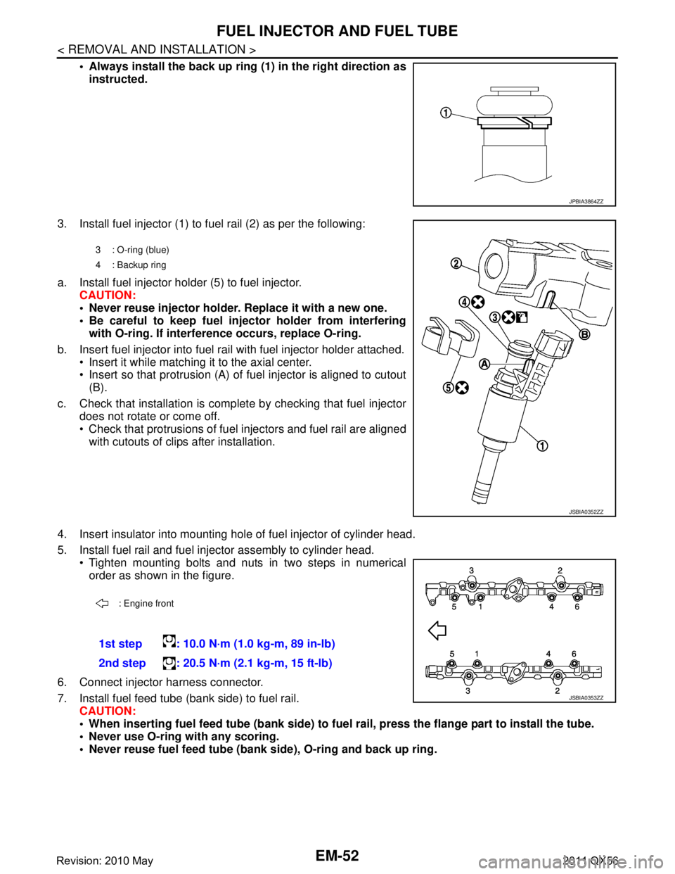
Always install the back up ring (1) in the right direction as
instructed.
3. Install fuel injector (1) to fuel rail (2) as per the following:
a. Install fuel injector holder (5) to fuel injector. CAUTION:
Never reuse injector holder. Replace it with a new one.
Be careful to keep fuel inject or holder from interfering
with O-ring. If interfer ence occurs, replace O-ring.
b. Insert fuel injector into fuel rail with fuel injector holder attached. Insert it while matching it to the axial center.
Insert so that protrusion (A) of fuel injector is aligned to cutout
(B).
c. Check that installation is complete by checking that fuel injector does not rotate or come off.
Check that protrusions of fuel in jectors and fuel rail are aligned
with cutouts of clips after installation.
4. Insert insulator into mounting hole of fuel injector of cylinder head.
5. Install fuel rail and fuel injector assembly to cylinder head. Tighten mounting bolts and nuts in two steps in numericalorder as shown in the figure.
6. Connect injector harness connector.
7. Install fuel feed tube (bank side) to fuel rail. CAUTION:
When inserting fuel feed tube (b ank side) to fuel rail, press the flange part to install the tube.
Never use O-ring with any scoring.
Never reuse fuel feed tube (ban k side), O-ring and back up ring.
JPBIA3864ZZ
3 : O-ring (blue)
4: Backup ring
JSBIA0352ZZ
: Engine front
1st step : 10.0 N·m (1.0 kg-m, 89 in-lb)
2nd step : 20.5 N·m (2.1 kg-m, 15 ft-lb)
JSBIA0353ZZ
Revision: 2010 May2011 QX56
Page 2615 of 5598

FUEL INJECTOR AND FUEL TUBEEM-53
< REMOVAL AND INSTALLATION >
C
DE
F
G H
I
J
K L
M A
EM
NP
O
Apply engine oil to O-ring.
Tighten mounting bolts in numerical order as shown in the fig-
ure.
8. Install fuel feed tube (pump side) to fuel feed tube (bank side) as per the following:
CAUTION:
Never reuse fuel feed tube (pump side).
a. Apply engine oil to flare screw parts of high pr essure pump side and fuel feed tube (bank side) side.
b. Manually tighten 2 flare nuts without using a t ool until they are seated to screw thread.
c. Tighten mounting bolt (A).
d. Tighten flare nuts in numerical order as shown in the figure.
9. Install in the reverse order of removal.
InspectionINFOID:0000000006289558
INSPECTION AFTER INSTALLATION
Check for Fuel Leakage
1. Turn ignition switch “ON” (with the engine stopped). With fuel pressure applied to fuel piping, check that
there is no fuel leakage at connection points.
NOTE:
Use mirrors for checking at points out of clear sight.
2. Start the engine. With engine speed increased, check again that there is no fuel leakage at connection
points.
CAUTION:
Never touch the engine immediately after it is stopped because the engine is extremely hot.
JPBIA3924ZZ
: Engine front
JSBIA0355ZZ
B :To high pressure fuel pump
: Engine front
JSBIA0356ZZ
Revision: 2010 May2011 QX56
Page 2646 of 5598
EM-84
< REMOVAL AND INSTALLATION >
CAMSHAFT
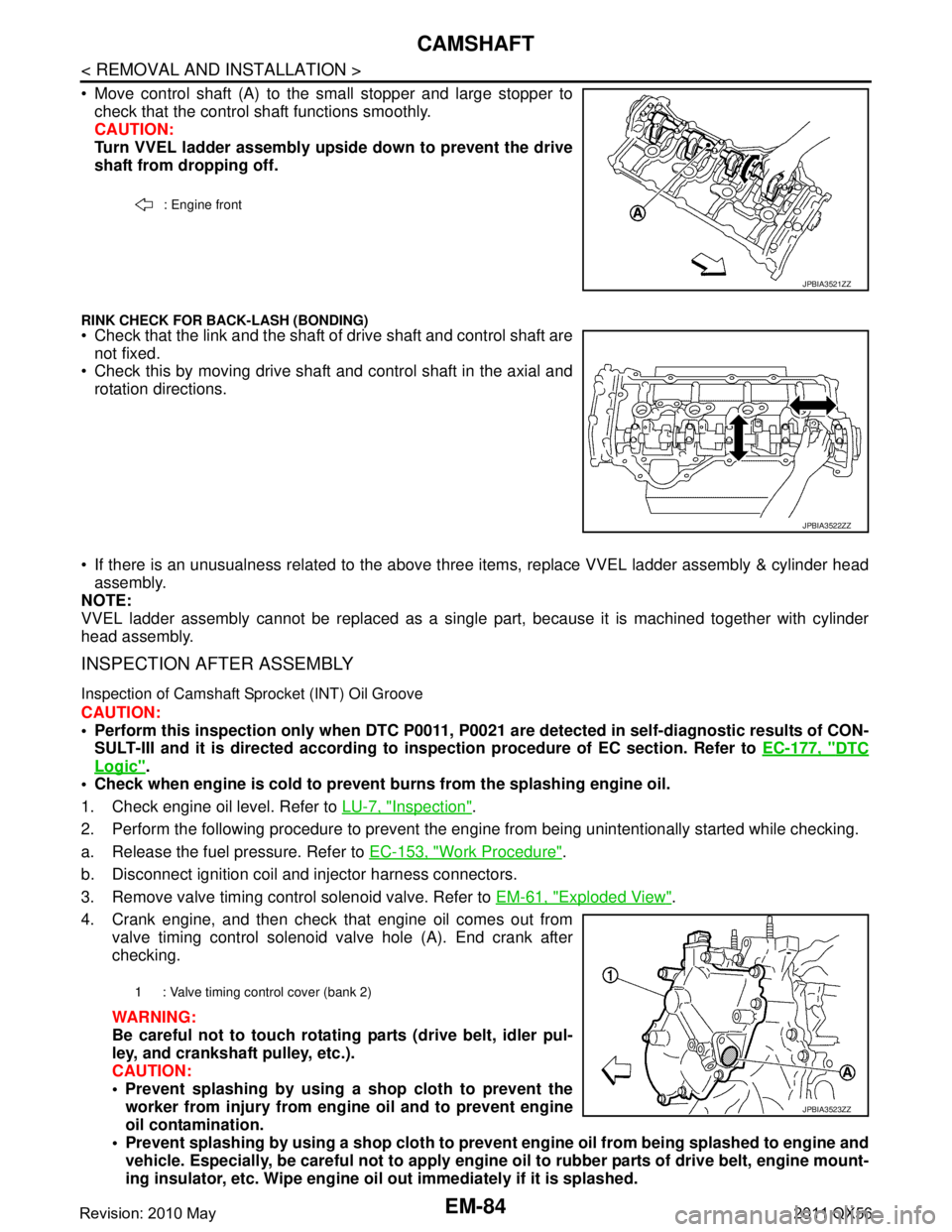
Move control shaft (A) to the small stopper and large stopper tocheck that the control shaft functions smoothly.
CAUTION:
Turn VVEL ladder assembly upside down to prevent the drive
shaft from dropping off.
RINK CHECK FOR BACK-LASH (BONDING) Check that the link and the shaft of drive shaft and control shaft are
not fixed.
Check this by moving drive shaft and control shaft in the axial and
rotation directions.
If there is an unusualness related to the above three items, replace VVEL ladder assembly & cylinder head
assembly.
NOTE:
VVEL ladder assembly cannot be replaced as a singl e part, because it is machined together with cylinder
head assembly.
INSPECTION AFTER ASSEMBLY
Inspection of Camshaft Sprocket (INT) Oil Groove
CAUTION:
Perform this inspection only when DTC P0011, P 0021 are detected in self-diagnostic results of CON-
SULT-III and it is directed according to inspection procedure of EC section. Refer to EC-177, "
DTC
Logic".
Check when engine is cold to prevent burns from the splashing engine oil.
1. Check engine oil level. Refer to LU-7, "
Inspection".
2. Perform the following procedure to prevent the engine from being unintentionally started while checking.
a. Release the fuel pressure. Refer to EC-153, "
Work Procedure".
b. Disconnect ignition coil and injector harness connectors.
3. Remove valve timing control solenoid valve. Refer to EM-61, "
Exploded View".
4. Crank engine, and then check that engine oil comes out from valve timing control solenoid valve hole (A). End crank after
checking.
WARNING:
Be careful not to touch rotati ng parts (drive belt, idler pul-
ley, and crankshaft pulley, etc.).
CAUTION:
Prevent splashing by using a shop cloth to prevent the worker from injury from en gine oil and to prevent engine
oil contamination.
Prevent splashing by using a shop cloth to prevent engine oil from being splashed to engine and
vehicle. Especially, be careful not to apply engine oil to rubber parts of drive belt, engine mount-
ing insulator, etc. Wipe engine oil out immediately if it is splashed.
: Engine front
JPBIA3521ZZ
JPBIA3522ZZ
1 : Valve timing control cover (bank 2)
JPBIA3523ZZ
Revision: 2010 May2011 QX56
Page 2665 of 5598
ENGINE STAND SETTINGEM-103
< UNIT DISASSEMBLY AND ASSEMBLY >
C
DE
F
G H
I
J
K L
M A
EM
NP
O
UNIT DISASSEMBLY AND ASSEMBLY
ENGINE STAND SETTING
SettingINFOID:0000000006289579
NOTE:
Explained here is how to disassemble with engine stand s
upporting transmission surface. When using a differ-
ent type of engine stand, note the difference in the steps, etc.
1. Remove the engine assembly from the vehicle. Refer to EM-98, "
Exploded View".
2. Remove crankshaft pulley. Refer to EM-96, "
FRONT OIL SEAL : Removal and Installation".
NOTE:
The drive plate is fixed with a ring gear stopper [SST: KV10119200 (J-49277)]. Loosen the crankshaft pul-
ley mounting bolts before installing the engine stand.
3. Remove the parts that may restrict installation of engine to a widely used engine stand. Fix crankshaft with a ring gear stopper [SST: KV10119200 (J-49277)]. Loosen drive plate mounting bolt
with power tool.
Check for deformation or damage of drive plate. Refer to EM-115, "
Inspection".
NOTE:
The procedure is described assuming that you us e a widely used engine stand holding the surface, to
which transmission is installed.
4. Remove pilot converter using the pilot bushing puller (commercial service tool), if necessary.
5. Lift the engine with hoist to inst all it onto the widely used engine stand.
CAUTION:
Use an engine stand that has a load capacity [240 kg (529 lb) or more] large enough for supporting
the engine weight.
If the load capacity of the stand is not adequate, remove the following parts beforehand to reduce the potential risk of overturning the stand.
- Remove intake manifold. Refer to EM-30, "
Exploded View".
- Remove fuel injector and fuel tube assembly. Refer to EM-48, "
Exploded View".
- Remove ignition coil. Refer to EM-29, "
Exploded View".
- Remove rocker cover. Refer to EM-33, "
Exploded View".
- Remove exhaust manifold. Refer to EM-40, "
Exploded View".
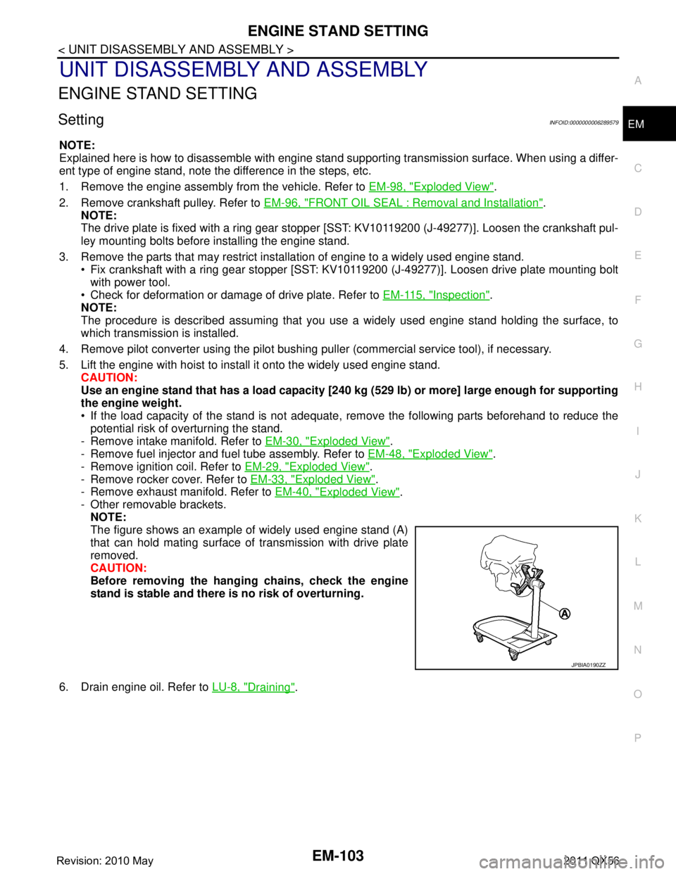
- Other removable brackets. NOTE:
The figure shows an example of widely used engine stand (A)
that can hold mating surface of transmission with drive plate
removed.
CAUTION:
Before removing the hang ing chains, check the engine
stand is stable and there is no risk of overturning.
6. Drain engine oil. Refer to LU-8, "
Draining".
JPBIA0190ZZ
Revision: 2010 May2011 QX56
Page 2979 of 5598
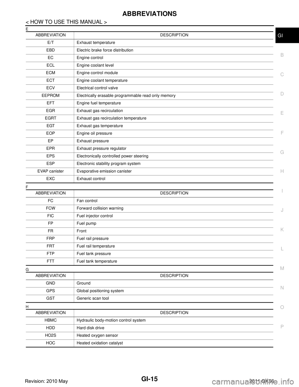
ABBREVIATIONSGI-15
< HOW TO USE THIS MANUAL >
C
DE
F
G H
I
J
K L
M B
GI
N
O P
E
F
G
H
ABBREVIATION DESCRIPTION E/T Exhaust temperature
EBD Electric brake force distribution EC Engine control
ECL Engine coolant level
ECM Engine control module ECT Engine coolant temperature
ECV Electrical control valve
EEPROM Electrically erasable programmable read only memory EFT Engine fuel temperature
EGR Exhaust gas recirculation
EGRT Exhaust gas recirculation temperature EGT Exhaust gas temperature
EOP Engine oil pressure EP Exhaust pressure
EPR Exhaust pressure regulator EPS Electronically controlled power steering
ESP Electronic stability program system
EVAP canister Evaporative emission canister EXC Exhaust control
ABBREVIATION DESCRIPTION FC Fan control
FCW Forward collision warning FIC Fuel injector controlFP Fuel pump
FR Front
FRP Fuel rail pressure FRT Fuel rail temperature
FTP Fuel tank pressure FTT Fuel tank temperature
ABBREVIATION DESCRIPTION GND GroundGPS Global positioning systemGST Generic scan tool
ABBREVIATION DESCRIPTION HBMC Hydraulic body-motion control systemHDD Hard disk drive
HO2S Heated oxygen sensor HOC Heated oxidation catalyst
Revision: 2010 May2011 QX56