engine ISUZU KB P190 2007 Workshop Owners Manual
[x] Cancel search | Manufacturer: ISUZU, Model Year: 2007, Model line: KB P190, Model: ISUZU KB P190 2007Pages: 6020, PDF Size: 70.23 MB
Page 620 of 6020
BRAKE CONTROL SYSTEM 5A-27
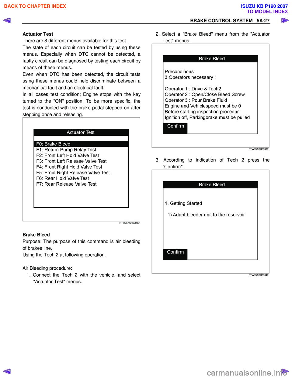
Actuator Test
There are 8 different menus available for this test.
The state of each circuit can be tested by using these
menus. Especially when DTC cannot be detected, a
faulty circuit can be diagnosed by testing each circuit b
y
means of these menus.
Even when DTC has been detected, the circuit tests
using these menus could help discriminate between a
mechanical fault and an electrical fault.
In all cases test condition; Engine stops with the ke
y
turned to the "ON" position. To be more specific, the
test is conducted with the brake pedal stepped on afte
r
stepping once and releasing.
RTW 75ASH000201
Brake Bleed
Purpose: The purpose of this command is air bleeding
of brakes line.
Using the Tech 2 at following operation.
Air Bleeding procedure: 1. Connect the Tech 2 with the vehicle, and select "Actuator Test" menus.
2. Select a "Brake Bleed" menu from the "Actuato
r
Test" menus.
RTW 75ASH000301
3. According to indication of Tech 2 press the
"Confirm".
RTW 75ASH000401
BACK TO CHAPTER INDEX
TO MODEL INDEX
ISUZU KB P190 2007
Page 622 of 6020
BRAKE CONTROL SYSTEM 5A-29
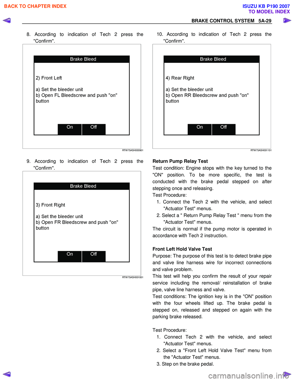
8. According to indication of Tech 2 press the
"Confirm".
RTW 75ASH000901
9. According to indication of Tech 2 press the
"Confirm".
RTW 75ASH001001
10. According to indication of Tech 2 press the
"Confirm".
RTW 75ASH001101
Return Pump Relay Test
Test condition: Engine stops with the key turned to the
"ON" position. To be more specific, the test is
conducted with the brake pedal stepped on afte
r
stepping once and releasing.
Test Procedure: 1. Connect the Tech 2 with the vehicle, and selec
t
"Actuator Test" menus.
2. Select a " Return Pump Relay Test " menu from the "Actuator Test" menus.
The circuit is normal if the pump motor is operated in
accordance with Tech 2 instruction.
Front Left Hold Valve Test
Purpose: The purpose of this test is to detect brake pipe
and valve line harness wire for incorrect connections
and valve problem.
This test will help you confirm the result of your repai
r
service including the removal/ reinstallation of brake
pipe, valve line harness and valve.
Test conditions: The ignition key is in the "ON" position
with the four wheels lifted up. The brake pedal is
stepped on, released and stepped on again with the
parking brake released.
Test Procedure: 1. Connect Tech 2 with the vehicle, and selec
t
"Actuator Test" menus.
2. Select a "Front Left Hold Valve Test" menu from the "Actuator Test" menus.
3. Step on the brake pedal.
BACK TO CHAPTER INDEX
TO MODEL INDEX
ISUZU KB P190 2007
Page 631 of 6020
5A-38 BRAKE CONTROL SYSTEM
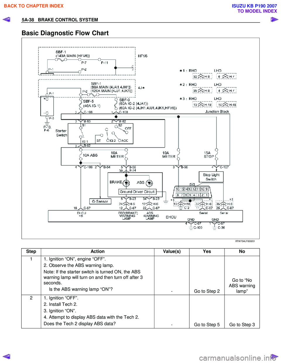
Basic Diagnostic Flow Chart
RTW 75ALF000201
Step Action Value(s) Yes No
1 1. Ignition “ON”, engine “OFF”.
2. Observe the ABS warning lamp. Note: If the starter switch is turned ON, the ABS
warning lamp will turn on and then turn off after 3
seconds.
Is the ABS warning lamp “ON”? - Go to Step 2 Go to “No
ABS warning lamp”
2 1. Ignition “OFF”.
2. Install Tech 2.
3. Ignition “ON”.
4. Attempt to display ABS data with the Tech 2. Does the Tech 2 display ABS data? - Go to Step 5 Go to Step 3
BACK TO CHAPTER INDEX
TO MODEL INDEX
ISUZU KB P190 2007
Page 638 of 6020
BRAKE CONTROL SYSTEM 5A-45
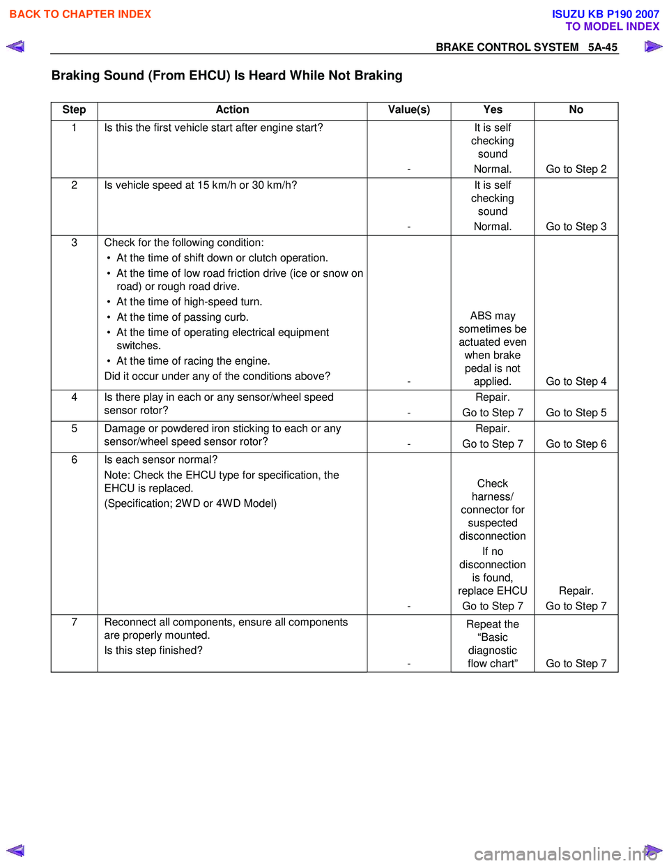
Braking Sound (From EHCU) Is Heard While Not Braking
Step Action Value(s) Yes No
1 Is this the first vehicle start after engine start?
- It is self
checking sound
Normal. Go to Step 2
2 Is vehicle speed at 15 km/h or 30 km/h?
- It is self
checking sound
Normal. Go to Step 3
3 Check for the following condition: • At the time of shift down or clutch operation.
• At the time of low road friction drive (ice or snow on road) or rough road drive.
• At the time of high-speed turn.
• At the time of passing curb.
• At the time of operating electrical equipment switches.
• At the time of racing the engine. Did it occur under any of the conditions above? - ABS may
sometimes be
actuated even when brake pedal is not applied. Go to Step 4
4 Is there play in each or any sensor/wheel speed sensor rotor? - Repair.
Go to Step 7 Go to Step 5
5 Damage or powdered iron sticking to each or any sensor/wheel speed sensor rotor? - Repair.
Go to Step 7 Go to Step 6
6 Is each sensor normal? Note: Check the EHCU type for specification, the
EHCU is replaced.
(Specification; 2W D or 4W D Model)
- Check
harness/
connector for suspected
disconnection
If no
disconnection is found,
replace EHCU
Go to Step 7 Repair.
Go to Step 7
7 Reconnect all components, ensure all components are properly mounted.
Is this step finished? - Repeat the
“Basic
diagnostic
flow chart” Go to Step 7
BACK TO CHAPTER INDEX
TO MODEL INDEX
ISUZU KB P190 2007
Page 639 of 6020
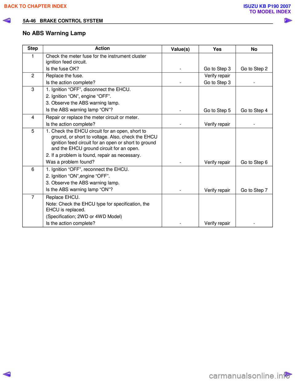
5A-46 BRAKE CONTROL SYSTEM
No ABS Warning Lamp
Step Action Value(s) Yes No
1 Check the meter fuse for the instrument cluster
ignition feed circuit.
Is the fuse OK? - Go to Step 3 Go to Step 2
2 Replace the fuse. Is the action complete? - Verify repair
Go to Step 3 -
3 1. Ignition “OFF”, disconnect the EHCU. 2. Ignition “ON”, engine “OFF”.
3. Observe the ABS warning lamp. Is the ABS warning lamp “ON”? - Go to Step 5 Go to Step 4
4 Repair or replace the meter circuit or meter.
Is the action complete? - Verify repair -
5 1. Check the EHCU circuit for an open, short to
ground, or short to voltage. Also, check the EHCU
ignition feed circuit for an open or short to ground
and the EHCU ground circuit for an open.
2. If a problem is found, repair as necessary. W as a problem found? - Verify repair Go to Step 6
6 1. Ignition “OFF”, reconnect the EHCU.
2. Ignition “ON”,engine “OFF”.
3. Observe the ABS warning lamp. Is the ABS warning lamp “ON”? - Verify repair Go to Step 7
7 Replace EHCU.
Note: Check the EHCU type for specification, the
EHCU is replaced.
(Specification; 2W D or 4W D Model)
Is the action complete? - Verify repair -
BACK TO CHAPTER INDEX
TO MODEL INDEX
ISUZU KB P190 2007
Page 640 of 6020
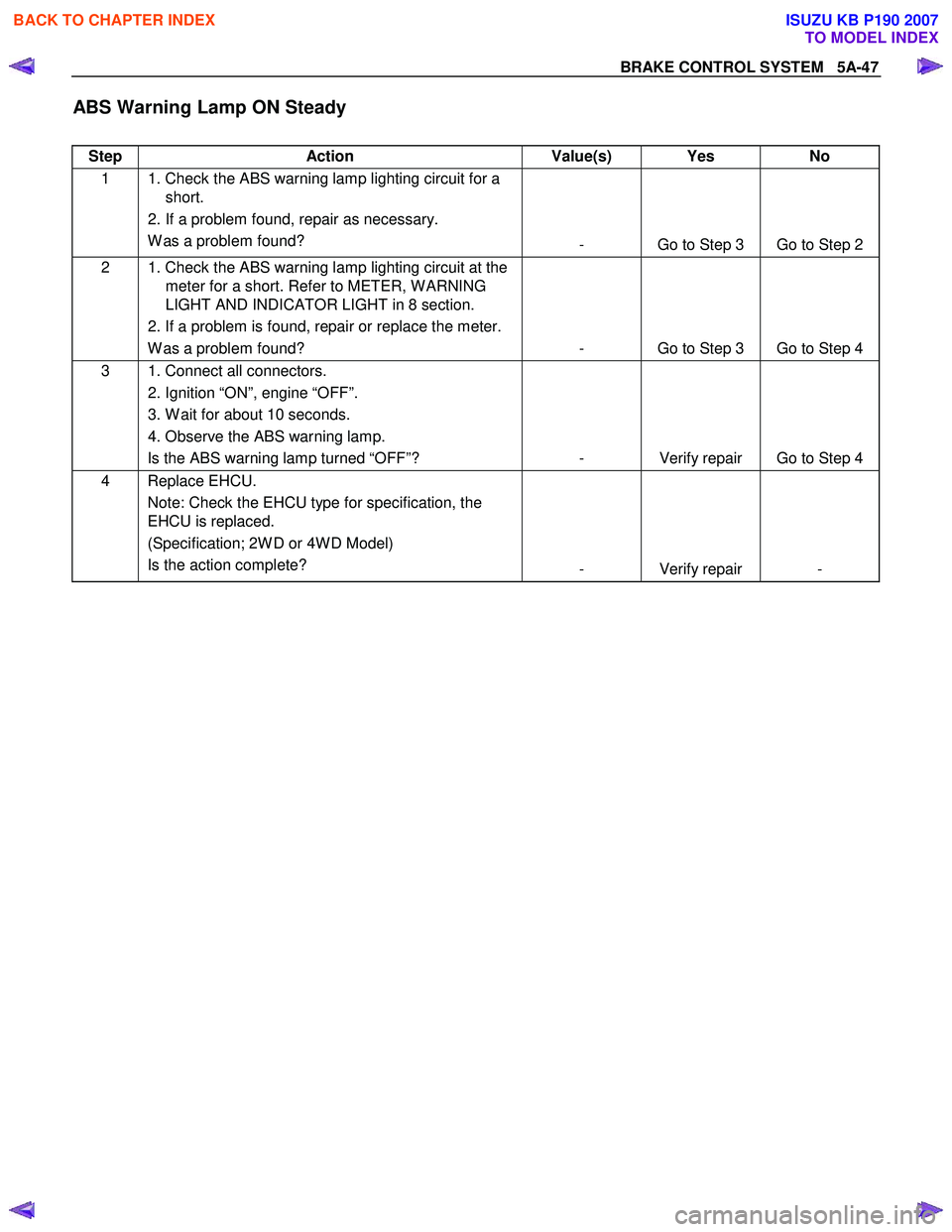
BRAKE CONTROL SYSTEM 5A-47
ABS Warning Lamp ON Steady
Step Action Value(s) Yes No
1 1. Check the ABS warning lamp lighting circuit for a
short.
2. If a problem found, repair as necessary. W as a problem found? - Go to Step 3 Go to Step 2
2 1. Check the ABS warning lamp lighting circuit at the
meter for a short. Refer to METER, W ARNING
LIGHT AND INDICATOR LIGHT in 8 section.
2. If a problem is found, repair or replace the meter. W as a problem found? - Go to Step 3 Go to Step 4
3 1. Connect all connectors.
2. Ignition “ON”, engine “OFF”.
3. W ait for about 10 seconds.
4. Observe the ABS warning lamp. Is the ABS warning lamp turned “OFF”? - Verify repair Go to Step 4
4 Replace EHCU.
Note: Check the EHCU type for specification, the
EHCU is replaced.
(Specification; 2W D or 4W D Model)
Is the action complete? - Verify repair -
BACK TO CHAPTER INDEX
TO MODEL INDEX
ISUZU KB P190 2007
Page 657 of 6020
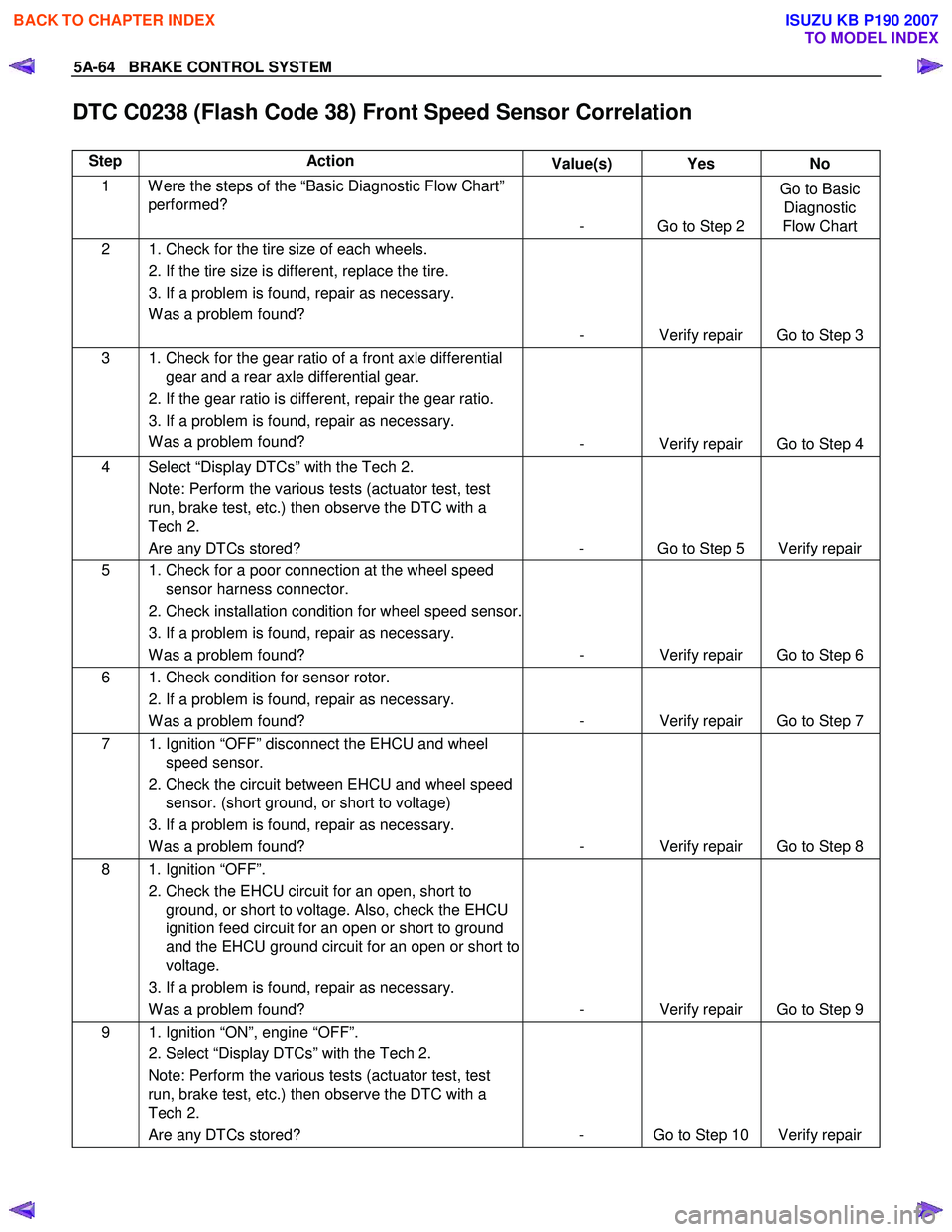
5A-64 BRAKE CONTROL SYSTEM
DTC C0238 (Flash Code 38) Front Speed Sensor Correlation
Step Action Value(s) Yes No
1 W ere the steps of the “Basic Diagnostic Flow Chart”
performed?
- Go to Step 2 Go to Basic
Diagnostic
Flow Chart
2 1. Check for the tire size of each wheels.
2. If the tire size is different, replace the tire.
3. If a problem is found, repair as necessary. W as a problem found? - Verify repair Go to Step 3
3 1. Check for the gear ratio of a front axle differential gear and a rear axle differential gear.
2. If the gear ratio is different, repair the gear ratio.
3. If a problem is found, repair as necessary. W as a problem found? - Verify repair Go to Step 4
4 Select “Display DTCs” with the Tech 2.
Note: Perform the various tests (actuator test, test
run, brake test, etc.) then observe the DTC with a
Tech 2.
Are any DTCs stored? - Go to Step 5 Verify repair
5 1. Check for a poor connection at the wheel speed sensor harness connector.
2. Check installation condition for wheel speed sensor.
3. If a problem is found, repair as necessary. W as a problem found? - Verify repair Go to Step 6
6 1. Check condition for sensor rotor.
2. If a problem is found, repair as necessary. W as a problem found? - Verify repair Go to Step 7
7 1. Ignition “OFF” disconnect the EHCU and wheel
speed sensor.
2. Check the circuit between EHCU and wheel speed sensor. (short ground, or short to voltage)
3. If a problem is found, repair as necessary. W as a problem found? - Verify repair Go to Step 8
8 1. Ignition “OFF”.
2. Check the EHCU circuit for an open, short to ground, or short to voltage. Also, check the EHCU
ignition feed circuit for an open or short to ground
and the EHCU ground circuit for an open or short to
voltage.
3. If a problem is found, repair as necessary. W as a problem found? - Verify repair Go to Step 9
9 1. Ignition “ON”, engine “OFF”.
2. Select “Display DTCs” with the Tech 2. Note: Perform the various tests (actuator test, test
run, brake test, etc.) then observe the DTC with a
Tech 2.
Are any DTCs stored? - Go to Step 10 Verify repair
BACK TO CHAPTER INDEX
TO MODEL INDEX
ISUZU KB P190 2007
Page 660 of 6020

BRAKE CONTROL SYSTEM 5A-67
Step Action
Value(s) Yes No
3 1. Ignition “ON”, engine “OFF”.
2. Select “Display DTCs” with the Tech 2. Note: Perform the various tests (actuator test, test
run, brake test, etc.) then observe the DTC with a
Tech 2.
Are any DTCs stored? - Go to Step 4 Verify repair
4 Replace EHCU.
Note: Check the EHCU type for specification, when
the EHCU is replaced.
(Specification ; 2W D model or 4W D model)
Is the action complete? - Verify repair -
BACK TO CHAPTER INDEX
TO MODEL INDEX
ISUZU KB P190 2007
Page 662 of 6020

BRAKE CONTROL SYSTEM 5A-69
Step Action
Value(s) Yes No
3 1. Ignition “ON”, engine “OFF”.
2. Select “Display DTCs” with the Tech 2. Note: Perform the various tests (actuator test, test
run, brake test, etc.) then observe the DTC with a
Tech 2.
Are any DTCs stored? - Go to Step 4 Verify repair
4 Replace EHCU.
Note: Check the EHCU type for specification, when
the EHCU is replaced.
(Specification ; 2W D model or 4W D model)
Is the action complete? - Verify repair -
BACK TO CHAPTER INDEX
TO MODEL INDEX
ISUZU KB P190 2007
Page 664 of 6020

BRAKE CONTROL SYSTEM 5A-71
Step Action
Value(s) Yes No
3 1. Ignition “ON”, engine “OFF”.
2. Select “Display DTCs” with the Tech 2. Note: Perform the various tests (actuator test, test
run, brake test, etc.) then observe the DTC with a
Tech 2.
Are any DTCs stored? - Go to Step 4 Verify repair
4 Replace EHCU.
Note: Check the EHCU type for specification, when
the EHCU is replaced.
(Specification ; 2W D model or 4W D model)
Is the action complete? - Verify repair -
BACK TO CHAPTER INDEX
TO MODEL INDEX
ISUZU KB P190 2007