ESP ISUZU KB P190 2007 Workshop Repair Manual
[x] Cancel search | Manufacturer: ISUZU, Model Year: 2007, Model line: KB P190, Model: ISUZU KB P190 2007Pages: 6020, PDF Size: 70.23 MB
Page 4094 of 6020
ON-VEHICLE SERVICE (AW30–40LE) 7A3-9
Manual Shifting Test
NOTE: W ith this test, it can be determined whether the
trouble lies within the electrical circuit or is a mechanical
problem in the transmission.
1. Disconnect TCM connector
2. Inspect manual driving operation
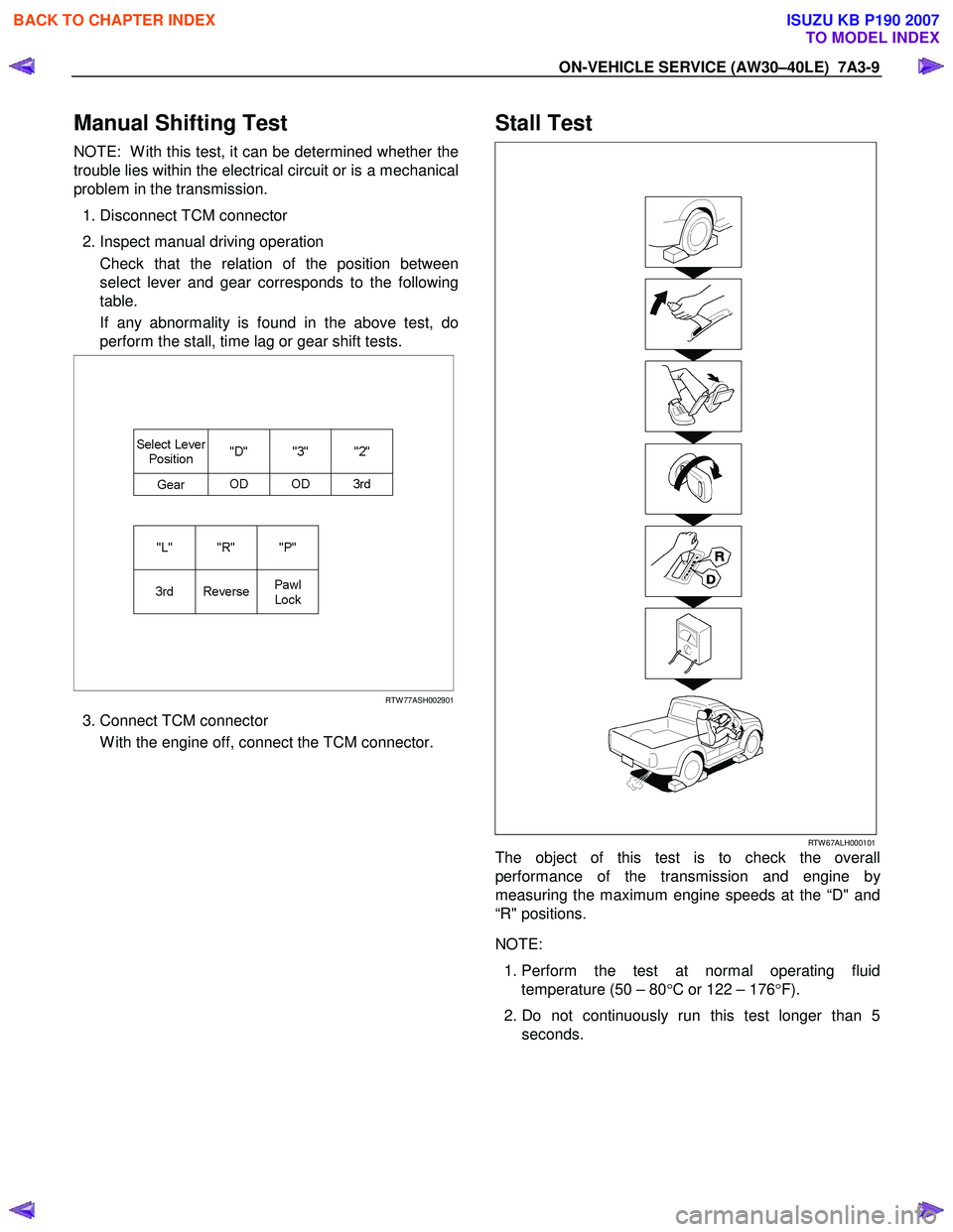
Check that the relation of the position between
select lever and gear corresponds to the following
table.
If any abnormality is found in the above test, do
perform the stall, time lag or gear shift tests.
RTW 77ASH002901
3. Connect TCM connector
W ith the engine off, connect the TCM connector.
Stall Test
RTW 67ALH000101
The object of this test is to check the overall
performance of the transmission and engine b
y
measuring the maximum engine speeds at the “D" and
“R" positions.
NOTE:
1. Perform the test at normal operating fluid
temperature (50 – 80 °C or 122 – 176 °F).
2. Do not continuously run this test longer than 5 seconds.
BACK TO CHAPTER INDEX
TO MODEL INDEX
ISUZU KB P190 2007
Page 4171 of 6020
7A4–36 UNIT REPAIR (AW30–40LE)
Diaassembly, Inspection and
Reassembly of minor Components
NOTE: The instructions here are organized so that you
work on only one component group at a time.
This will help avoid confusion from similar-looking parts
of different subassemblies being on your workbench at
the same time.
The component groups are inspected and repaired from
the converter housing side.
As much as possible, complete the inspection, repair
and reassembly before proceeding to the next
component group. If a component group cannot be
reassembled because parts are being ordered, be sure
to keep all parts of that group in separate container
while proceeding with disassembly, inspection, repair
and reassembly of other component groups.
Recommended ATF type DEXRON III.
General Cleaning Notes:
1. All disassembled parts should be washed clean and any fluid passages and holes should be blown
through with compressed air.
2. When using compressed air to dry parts, always aim away from yourself to prevent accidentally spraying
automatic transmission fluid in your face.
3. The recommended automatic transmission fluid should be used for cleaning.
Parts Arrangement:
1. After cleaning, the parts should be arranged inproper order to allow performing inspection, repairs,
and reassembly with efficiency.
2. When disassembling a valve body, be sure to keep each valve together with the corresponding spring.
3. New brakes and clutches that are to be used for replacement must be soaked in transmission fluid
for at least thirty minutes before assembly.
General Assembly:
1. All oil seal rings, clutch discs, clutch plates, rotating parts, and sliding surfaces should be coated with
transmission fluid prior to reassembly.
2. All gaskets and rubber O-ring should be replaced.
3. Make sure that the ends of a snap ring are not aligned with one of the cutouts and are installed in
the groove correctly.
4. If a worn bushing is to be replaced, the subassembly containing that bushing must be
replaced.
5. Check thrust bearings and races for wear or damage. Replace if necessary.
6. Use petroleum jelly or vaseline to keep parts in place.
BACK TO CHAPTER INDEX
TO MODEL INDEX
ISUZU KB P190 2007
Page 4253 of 6020

7A1-14 CONSTRUCTION AND FUNCTION
CONTROL VALVE
• Employing the direct electronic control (Direct Electronic Shift Control: DESC) for the clutch pressure has
simplified the oil pressure circuit, reduced the number of functional components and made the control
valve compact.
• The control valve body is divided into the upper body and the lower body. All solenoids, the oil pressure
switch and the ATF thermo sensor are installed to the lower body.
• Three-way valve type solenoids providing high responsibility are employed. Some of the solenoids are
switched between ON and OFF, and others repeat ON and OFF at 50Hz (duty cycle system).
Functionally, some supply output pressure when power is not supplied, and others drain the output
pressure.
• When the solenoid is driven based on the signal from the TCM, the oil pressure is changed.
Figure 22. Construction of Valve Body
BACK TO CHAPTER INDEX
TO MODEL INDEX
ISUZU KB P190 2007
Page 4254 of 6020
CONSTRUCTION AND FUNCTION 7A1-15
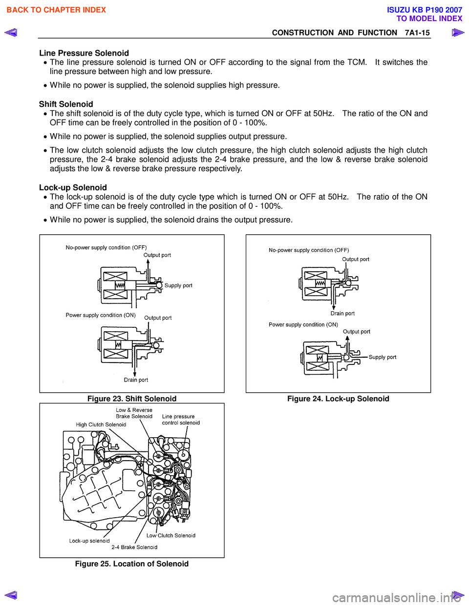
Line Pressure Solenoid • The line pressure solenoid is turned ON or OFF according to the signal from the TCM. It switches the
line pressure between high and low pressure.
• While no power is supplied, the solenoid supplies high pressure.
Shift Solenoid • The shift solenoid is of the duty cycle type, which is turned ON or OFF at 50Hz. The ratio of the ON and
OFF time can be freely controlled in the position of 0 - 100%.
• While no power is supplied, the solenoid supplies output pressure.
• The low clutch solenoid adjusts the low clutch pressure, the high clutch solenoid adjusts the high clutch
pressure, the 2-4 brake solenoid adjusts the 2-4 brake pressure, and the low & reverse brake solenoid
adjusts the low & reverse brake pressure respectively.
Lock-up Solenoid • The lock-up solenoid is of the duty cycle type which is turned ON or OFF at 50Hz. The ratio of the ON
and OFF time can be freely controlled in the position of 0 - 100%.
• While no power is supplied, the solenoid drains the output pressure.
Figure 23. Shift Solenoid Figure 24. Lock-up Solenoid
Figure 25. Location of Solenoid
BACK TO CHAPTER INDEX
TO MODEL INDEX
ISUZU KB P190 2007
Page 4255 of 6020
7A1-16 CONSTRUCTION AND FUNCTION
Control Valve Fail-safe Function • To prevent interlocking due to engagement of more than three clutches and brakes at the same time, the
2-4 brake fail-safe valve A and B, and the low & reverse brake fail-safe valve A and B are provided.
• When oil pressure is generated in the high clutch and the low clutch, the 2-4 brake solenoid is turned ON
to drain the oil pressure applied to the 2-4 brake.
• When oil pressure is generated in the high clutch or 2-4 brake, the low & reverse brake solenoid is turned
ON to drain the oil pressure applied to the low & reverse brake.
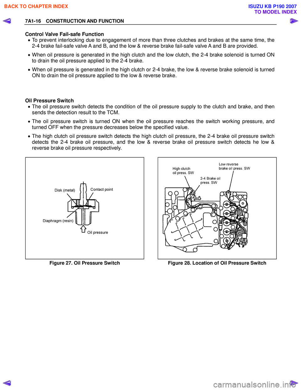
Oil Pressure Switch • The oil pressure switch detects the condition of the oil pressure supply to the clutch and brake, and then
sends the detection result to the TCM.
• The oil pressure switch is turned ON when the oil pressure reaches the switch working pressure, and
turned OFF when the pressure decreases below the specified value.
• The high clutch oil pressure switch detects the high clutch oil pressure, the 2-4 brake oil pressure switch
detects the 2-4 brake oil pressure, and the low & reverse brake oil pressure switch detects he low &
reverse brake oil pressure respectively.
Figure 27. Oil Pressure Switch Figure 28. Location of Oil Pressure Switch
BACK TO CHAPTER INDEX
TO MODEL INDEX
ISUZU KB P190 2007
Page 4270 of 6020

CONSTRUCTION AND FUNCTION 7A1-31
As a result, the lock-up piston is fitted slowly to the converter cover under pressure securing smooth lock-
up engagement.
Figure 51. Lock-up Control
DIRECT ELECTRIC SHIFT CONTROL (DESC)
Feature
• Based on each switch signal (low & reverse brake pressure, 2-4 brake pressure & high clutch pressure)
and each sensor signal (turbine sensor, speed sensor, engine speed signal & APP position signal), the
duty cycle type solenoid adjusts the clutch pressure to match the engine load and vehicle travel
conditions. Controlling the engagement and disengagement of the clutch and brake pressure is directly
and accurately controlled via TCM, which is different to the previous accumulator type.
Operation
• Instead of the previous system (on/off type of shift solenoid and shift valve), the combination of the duty
cycle type solenoid and the amplifier (Amp) valve are used to adjust the clutch pressure to match the
engine load and vehicle travel conditions, based on the signal from the TCM. Also, the pressure switch
provided in the oil passage of the control valve transmits the oil pressure condition (at that time) to TCM,
enabling the engagement and disengagement control of the clutch and brake to be directly and finely
carried out.
• When the gear is shifted from the 2nd to 3rd, 3rd to 4th (O/D), 4th (O/D) to 3rd and 3rd to 2nd, the clutch
pressures on the engagement side and disengagement side are simultaneously controlled.
As a result, engine racing or clutch drag is prevented which enables a smooth and quick shift response.
BACK TO CHAPTER INDEX
TO MODEL INDEX
ISUZU KB P190 2007
Page 4395 of 6020

TRANSMISSION CONTROL SYSTEM (JR405E) 7A2-111
D2: Gearshift Frequently
Diagnosis Hints• When inspecting faulty gear shifting, it is important to distinguish between
the fault of the electric system and transmission main unit.
• Fault of electric system. - Monitor the output signal (each solenoid driving signal) using a scan tool. If a trouble signal is sent to the solenoid synchronously with the faulty
gear shifting, the fault is originated in the electric system.
- Monitor the input signal (signal from each sensor) using a scan tool and find an input signal which has an output signal (each solenoid driving
signal) subjected to a fault.
- Fault of the electric system may be derived from temperature or vibration. For instance, although the engine is normal while it is cold, fault may
occur when the engine is warmed up or the vehicle is running.
• Fault of mechanical system. - If the gear is incorrectly shifted, irrespective of the operating signal (On/ Off) of each solenoid, the fault is originated from the transmission main
unit.
- If the clutch slips, or the transmission fluid smells burnt or is contaminated or black, or the stall speed increases. Gear ratio error DTC might be set.
Transmission Range Switch & Selector
Lever Cable Checks Inspect the transmission range switch and selector lever cable for misadjusting
or disordering. Refer to On-Vehicle Service section.
Transmission Fluid Checks Inspect the transmission fluid for the following conditions. If the transmission fluid
is extremely blacked, contaminated or smells burnt, slipping of clutch is
suspected.
• Low quantity
• Contamination
•Smell
Line Pressure Checks Inspect the line pressure in forward ranges for a possible dropped pressure.
Refer to Line Pressure Test in Test Instruction section.
Stall Speed Checks Inspect the stall speed in forward ranges. Refer to Stall Test in Test Instruction
section.
Control Valve Body Checks Inspect the valve body for the following conditions.
• Faulty operation
• Sticking spool valve
• Sticking shift solenoid valve. Perform function check. Refer to On-Vehicle Service section.
• Faulty operation of transmission fluid pressure switch. Perform function check. Refer to On-Vehicle Service section.
• Clogged hydraulic circuit
Checks
Action
Checks Action
Definition:
Shift down or engine overrun occurs above than kick-down area.
Diagnosis Hints The same causes as in category No. “C1 - C8: Engine Race Up (Slipping)” are
suspected.
BACK TO CHAPTER INDEX
TO MODEL INDEX
ISUZU KB P190 2007
Page 4432 of 6020
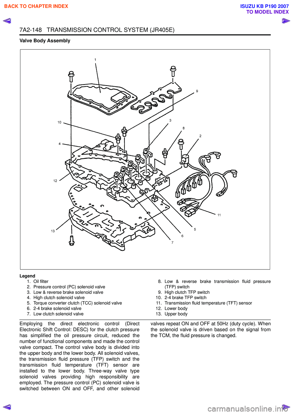
7A2-148 TRANSMISSION CONTROL SYSTEM (JR405E)
Valve Body Assembly
Legend1. Oil filter
2. Pressure control (PC) solenoid valve
3. Low & reverse brake solenoid valve
4. High clutch solenoid valve
5. Torque converter clutch (TCC) solenoid valve
6. 2-4 brake solenoid valve
7. Low clutch solenoid valve 8. Low & reverse brake transmission fluid pressure
(TFP) switch
9. High clutch TFP switch
10. 2-4 brake TFP switch
11. Transmission fluid temperature (TFT) sensor
12. Lower body
13. Upper body
Employing the direct electronic control (Direct
Electronic Shift Control: DESC) for the clutch pressure
has simplified the oil pressure circuit, reduced the
number of functional components and made the control
valve compact. The control valve body is divided into
the upper body and the lower body. All solenoid valves,
the transmission fluid pressure (TFP) switch and the
transmission fluid temperature (TFT) sensor are
installed to the lower body. Three-way valve type
solenoid valves providing high responsibility are
employed. The pressure control (PC) solenoid valve is
switched between ON and OFF, and other solenoid valves repeat ON and OFF at 50Hz (duty cycle). When
the solenoid valve is driven based on the signal from
the TCM, the fluid pressure is changed.
BACK TO CHAPTER INDEX
TO MODEL INDEX
ISUZU KB P190 2007
Page 4433 of 6020
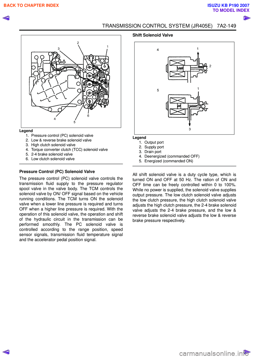
TRANSMISSION CONTROL SYSTEM (JR405E) 7A2-149
Legend1. Pressure control (PC) solenoid valve
2. Low & reverse brake solenoid valve
3. High clutch solenoid valve
4. Torque converter clutch (TCC) solenoid valve
5. 2-4 brake solenoid valve
6. Low clutch solenoid valve
Pressure Control (PC) Solenoid Valve
The pressure control (PC) solenoid valve controls the
transmission fluid supply to the pressure regulator
spool valve in the valve body. The TCM controls the
solenoid valve by ON/ OFF signal based on the vehicle
running conditions. The TCM turns ON the solenoid
valve when a lower line pressure is required and turns
OFF when a higher line pressure is required. With the
operation of this solenoid valve, the operation and shift
of the hydraulic circuit in the transmission can be
performed smoothly. The PC solenoid valve is
controlled according to the range position, speed
sensor signals, transmission fluid temperature signal
and the accelerator pedal position signal. Shift Solenoid Valve
Legend
1. Output port
2. Supply port
3. Drain port
4. Deenergized (commanded OFF)
5. Energized (commanded ON)
All shift solenoid valve is a duty cycle type, which is
turned ON and OFF at 50 Hz. The ration of ON and
OFF time can be freely controlled within 0 to 100%.
While no power is supplied, the solenoid valve supplies
output pressure. The low clutch solenoid valve adjusts
the low clutch pressure, the high clutch solenoid valve
adjusts the high clutch pressure, the 2-4 brake solenoid
valve adjusts the 2-4 brake pressure, and the low &
reverse brake solenoid valve adjusts the low & reverse
brake pressure respectively.
BACK TO CHAPTER INDEX
TO MODEL INDEX
ISUZU KB P190 2007
Page 4434 of 6020
7A2-150 TRANSMISSION CONTROL SYSTEM (JR405E)
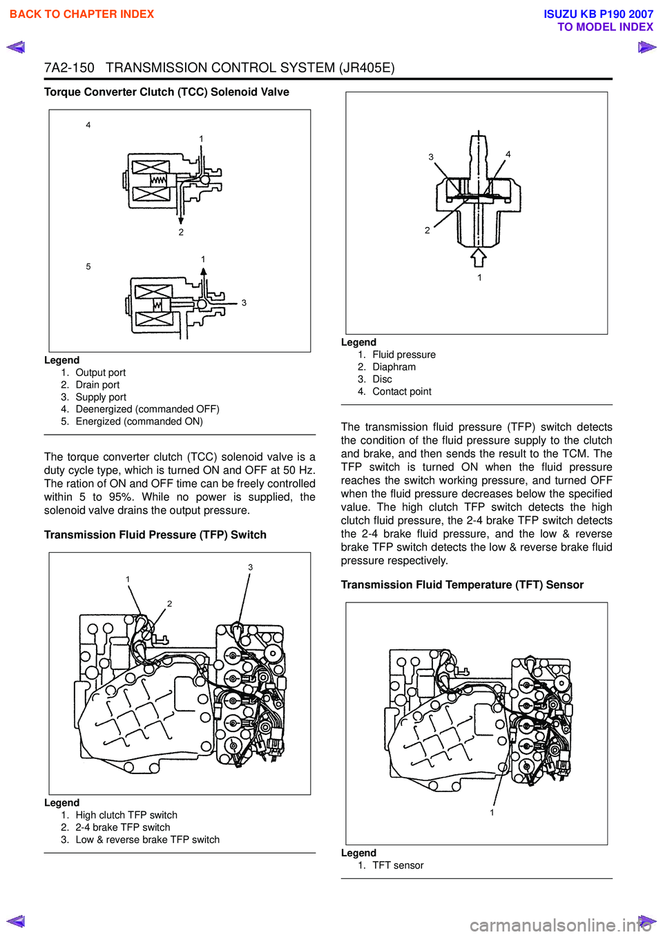
Torque Converter Clutch (TCC) Solenoid Valve
Legend1. Output port
2. Drain port
3. Supply port
4. Deenergized (commanded OFF)
5. Energized (commanded ON)
The torque converter clutch (TCC) solenoid valve is a
duty cycle type, which is turned ON and OFF at 50 Hz.
The ration of ON and OFF time can be freely controlled
within 5 to 95%. While no power is supplied, the
solenoid valve drains the output pressure.
Transmission Fluid Pressure (TFP) Switch
Legend 1. High clutch TFP switch
2. 2-4 brake TFP switch
3. Low & reverse brake TFP switch
Legend
1. Fluid pressure
2. Diaphram
3. Disc
4. Contact point
The transmission fluid pressure (TFP) switch detects
the condition of the fluid pressure supply to the clutch
and brake, and then sends the result to the TCM. The
TFP switch is turned ON when the fluid pressure
reaches the switch working pressure, and turned OFF
when the fluid pressure decreases below the specified
value. The high clutch TFP switch detects the high
clutch fluid pressure, the 2-4 brake TFP switch detects
the 2-4 brake fluid pressure, and the low & reverse
brake TFP switch detects the low & reverse brake fluid
pressure respectively.
Transmission Fluid Temperature (TFT) Sensor
Legend
1. TFT sensor
BACK TO CHAPTER INDEX
TO MODEL INDEX
ISUZU KB P190 2007