check engine ISUZU KB P190 2007 Workshop Repair Manual
[x] Cancel search | Manufacturer: ISUZU, Model Year: 2007, Model line: KB P190, Model: ISUZU KB P190 2007Pages: 6020, PDF Size: 70.23 MB
Page 5285 of 6020

ELECTRICAL-BODY AND CHASSIS 8A-347
ENGINE COOLANT TEMPERATURE GAUGE (4JJ1-TC/4JK1-TC)
Refer to “Inspection and Repair” in this Manual for a detailed description of the coolant temperature gauge self-
diagnosis procedure.
1. No engine coolant temperature indicates at all
Checkpoint Trouble Cause Countermeasure
Replace the engine coolant
temperature sensor
Engine coolant temperature
sensor malfunction
NG
Replace the meter assembly
Gauge function
1. Disconnect the sensor connector then connect
3.4W bulb to wire harness
side with ground
2. Check indicating point when starter SW . is ON
position (Temperature
should indicate)
Gauge malfunction
Repair open circuit or
connector contact
Continuity between 3
E41
and 16
B23
Open circuit or poor connector
contact
NG
NG
OK
OK
Engine coolant temperature
sensor continuity between
connector 3
E41 and the
ground
2. Engine coolant temperature gauge incorrect readings in all ranges
Replace the sensor
The sensor malfunction
NG
Engine coolant temperature
sensor resistance between
connector 3
E41 and the
ground when disconnecting
the connector (Specified
resistance should indicate)
BACK TO CHAPTER INDEX
TO MODEL INDEXISUZU KB P190 2007
Page 5290 of 6020

8A-352 ELECTRICAL-BODY AND CHASSIS
2. When the parking brake lever is released, the indicator light does not go off
Checkpoint Trouble Cause Countermeasure
Adjust the SW . installation
position or replace the parking
brake SW . Incorrect the parking brake
SW . adjustment or parking
brake SW . faulty
NG
Thermo unit malfunction
Replace the brake fluid level
SW ., or repair a short circuit
between the parking brake
SW . connector 1
C39,
1
R4 and 4 B23 (C24SE :
9
B23 ) or the brake fluid
level SW . connector 2
C37
and 4
B23 (C24SE : 9
B23 )
Check to see if the indicator
light goes off when the parking
brake SW . connector 1
C39
(stick type), 1
R4 (lever
type) is disconnected
Brake fluid level SW . faulty or
short circuit
NG
OK
Parking brake SW . installation
position and function
3. Oil pressure warning light does not go off while engine is running
Refer to ENGINE Section
Refer to ENGINE Section
NG Thermo unit malfunction
Check to see the warning light
goes off when the oil pressure
SW . connector
1
E1 is disconnected or
when the PIM (Oil pressure)
connector 6
B96 (HFV6) is
disconnected
Repair a short circuit between
1
E1 and 39 B23
(C24SE : 17
B24) or 6
B96 and 39 B23 (HFV6)
Short circuit
NG
OK
Replace the oil pressure SW .
Continuity between the oil
pressure SW . connector
1
E1 (HFV6 : 6 B96 )and
the body ground when the
engine is operating
Oil pressure SW . faulty
NG
OK
Engine oil pressure
BACK TO CHAPTER INDEX TO MODEL INDEXISUZU KB P190 2007
Page 5303 of 6020

ELECTRICAL-BODY AND CHASSIS 8A-365
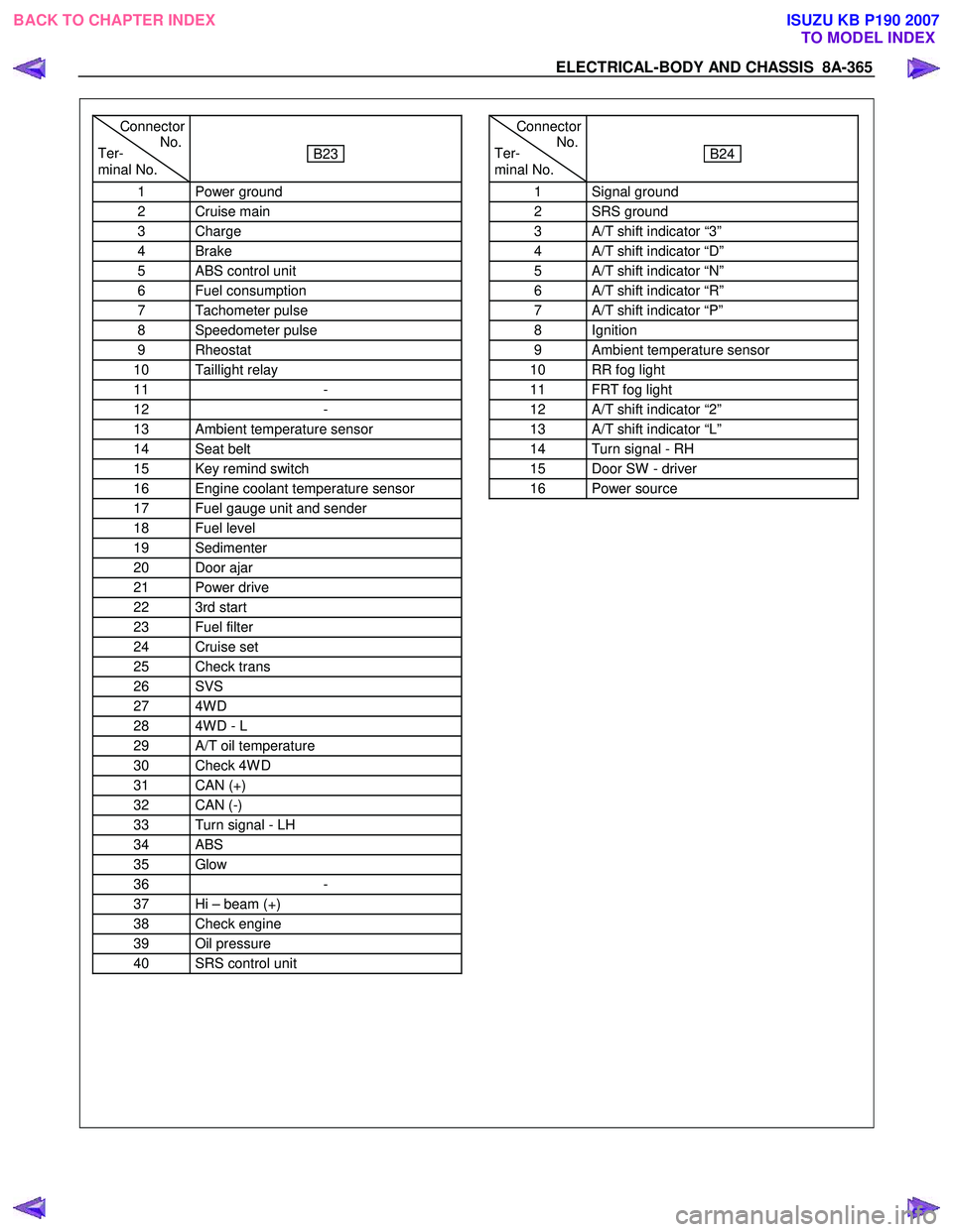
Connector
Ter- No.
minal No.
B23
1 Power ground
2 Cruise main
3 Charge
4 Brake
5 ABS control unit
6 Fuel consumption
7 Tachometer pulse
8 Speedometer pulse
9 Rheostat
10 Taillight relay
11 -
12 -
13 Ambient temperature sensor
14 Seat belt
15 Key remind switch
16 Engine coolant temperature sensor
17 Fuel gauge unit and sender
18 Fuel level
19 Sedimenter
20 Door ajar
21 Power drive
22 3rd start
23 Fuel filter
24 Cruise set
25 Check trans
26 SVS
27 4W D
28 4W D - L
29 A/T oil temperature
30 Check 4W D
31 CAN (+)
32 CAN (-)
33 Turn signal - LH
34 ABS
35 Glow
36 -
37 Hi – beam (+)
38 Check engine
39 Oil pressure
40 SRS control unit
Connector
Ter- No.
minal No.
B24
1 Signal ground
2 SRS ground
3 A/T shift indicator “3”
4 A/T shift indicator “D”
5 A/T shift indicator “N”
6 A/T shift indicator “R”
7 A/T shift indicator “P”
8 Ignition
9 Ambient temperature sensor
10 RR fog light
11 FRT fog light
12 A/T shift indicator “2”
13 A/T shift indicator “L”
14 Turn signal - RH
15 Door SW - driver
16 Power source
BACK TO CHAPTER INDEX TO MODEL INDEXISUZU KB P190 2007
Page 5304 of 6020

8A-366 ELECTRICAL-BODY AND CHASSIS
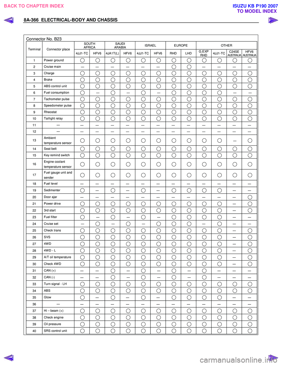
Connector No. B23 SOUTH
AFRICA SAUDI
ARABIA ISRAEL EUROPE OTHER
Terminal Connector place
4JJ1-TC HFV6 4JA1T(L) HFV6 4JJ1-TC HFV6 RHD LHD G.EXP
RHD 4JJ1-TC
C24SE
AUSTRALIAHFV6AUSTRALIA
1
Power ground
2 Cruise main
―
― ― ― ― ― ― ― ― ―
3
Charge
4 Brake
5 ABS control unit
6 Fuel consumption ―
―
―
―
―
7 Tachometer pulse
8 Speedometer pulse
9 Rheostat
10 Taillight relay
11 ―
― ― ― ― ― ― ― ― ― ― ― ―
12 ―
― ― ― ― ― ― ― ― ― ― ― ―
13 Ambient
temperature sensor ―
14 Seat belt
15 Key remind switch
16 Engine coolant
temperature sensor
17 Fuel gauge unit and
sender
18 Fuel level
― ― ― ― ― ― ― ― ― ― ― ―
19 Sedimenter ―
―
―
―
―
20 Door ajar
― ― ― ― ― ― ― ― ― ― ―
21 Power drive ―
22 3rd start ―
23 Fuel filter ―
―
―
―
―
24 Cruise set
― ―
―
―
―
―
25 Check trans ―
26 SVS ―
27 4W D ―
28 4W D - L ―
29 A/T oil temperature ―
30 Check 4W D ―
31 CAN (+)
― ― ―
―
―
― ― ―
32
CAN (-)
― ― ―
―
―
― ― ―
33
Turn signal - LH
34 ABS
35 Glow ―
―
―
―
―
36 ―
― ― ― ― ― ― ― ― ― ― ― ―
37 Hi – beam (+)
38 Check engine
39 Oil pressure
40 SRS control unit
BACK TO CHAPTER INDEX
TO MODEL INDEXISUZU KB P190 2007
Page 5307 of 6020

ELECTRICAL-BODY AND CHASSIS 8A-369
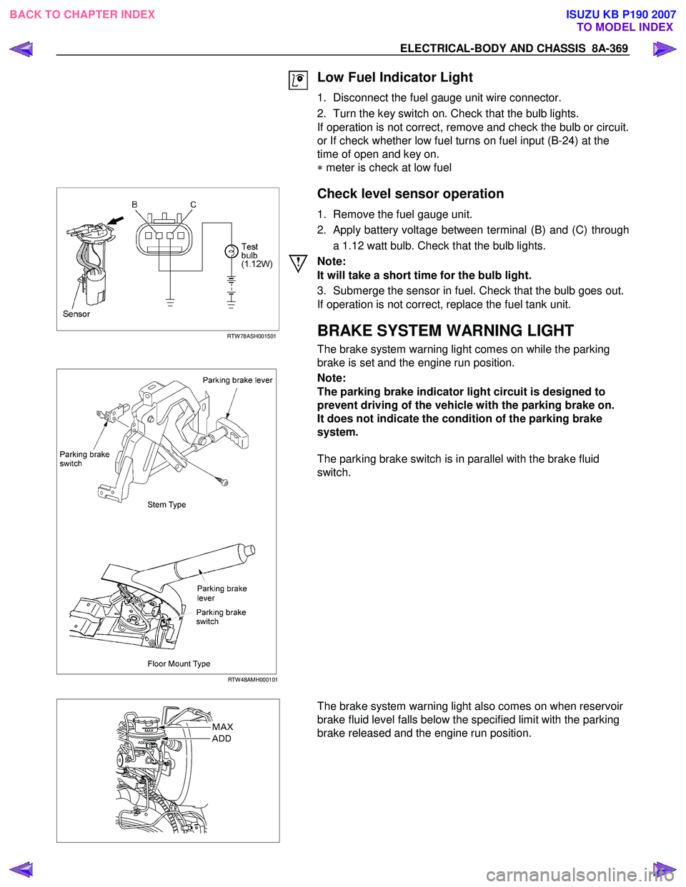
Low Fuel Indicator Light
1. Disconnect the fuel gauge unit wire connector.
2. Turn the key switch on. Check that the bulb lights.
If operation is not correct, remove and check the bulb or circuit.
or If check whether low fuel turns on fuel input (B-24) at the
time of open and key on.
∗ meter is check at low fuel
RTW 78ASH001501
Check level sensor operation
1. Remove the fuel gauge unit.
2. Apply battery voltage between terminal (B) and (C) through a 1.12 watt bulb. Check that the bulb lights.
Note:
It will take a short time for the bulb light.
3. Submerge the sensor in fuel. Check that the bulb goes out.
If operation is not correct, replace the fuel tank unit.
BRAKE SYSTEM WARNING LIGHT
The brake system warning light comes on while the parking
brake is set and the engine run position.
RTW 48AMH000101
Note:
The parking brake indicator light circuit is designed to
prevent driving of the vehicle with the parking brake on.
It does not indicate the condition of the parking brake
system.
The parking brake switch is in parallel with the brake fluid
switch.
The brake system warning light also comes on when reservoir
brake fluid level falls below the specified limit with the parking
brake released and the engine run position.
BACK TO CHAPTER INDEX TO MODEL INDEXISUZU KB P190 2007
Page 5579 of 6020

Cruise Control – HFV6 Page 8C–1
8C
Cruise Control – HFV6
ATTENTION
Before performing any Service Operation or other procedure described in this Section, refer to General Information Warnings, Cautions and Notes for correct workshop practices with regard to safety and/or property damage.
1 General Information ...............................................................................................................................3
1.1 WARNINGS, CAUTIONS and NOTES................................................................................................... ................. 3
Definition of WARNING, CAUTION and NOTE Statements ............................................................................. .... 3
WARNING Defined............................................................................................................................................. 3
CAUTION Defined .............................................................................................................................................. 3
NOTE Defined .................................................................................................................................................... 4
1.2 System Components .............................................................................................................. ............................... 4
Cruise Control Switch Assembly ................................................................................................. ....................... 5
Instrument Cluster Assembly ............................................................................................................................. 5
Clutch Pedal Switch (Manual Only) .............................................................................................. ...................... 5
Stop Lamp Switch Assembly .............................................................................................................................. 5
Powertrain Interface Module .............................................................................................................................. 6
Engine Control Module ....................................................................................................................................... 6
Throttle Actuator Control (TAC) Assembly ....................................................................................... .................. 6
1.3 System Operation .................................................................................................................................................. 6
Preliminary Information......................................................................................................................................... 6
Enabled and Disabled ........................................................................................................... ............................. 6
Activated and Deactivated...................................................................................................... ............................ 7
Enabling the Cruise Control.................................................................................................... .............................. 7
Brake Before Cruise .............................................................................................................................................. 7
Activating the Cruise Control .................................................................................................. ............................. 7
Deactivating the Cruise Control ................................................................................................ ........................... 7
Pressing the Brake Pedal ................................................................................................................................... 7
Pressing the Cruise ON–OFF Button .............................................................................................. ................... 8
Rotating the Cruise Control Switch Assembly .................................................................................... ................ 8
Pressing the Clutch Pedal (Manual Vehicles Only) ............................................................................... ............. 8
Decelerating While Cruise Control is Activated ................................................................................. ................. 8
Resuming a Speed After Cruise Control Has Been Deactivated ..................................................................... .. 8
Accelerating While Cruise Control is Activated .................................................................................................. 8
Using the Cruise Control Switch Assembly ........................................................................................................ 8
Pressing the Accelerator Pedal .......................................................................................................................... 8
2 Diagnostics .............................................................................................................................................9
2.1 Diagnostic General Information............................................................................................................................ 9
Basic Knowledge Required ................................................................................................................................... 9
Basic Diagnostic Tools Required ......................................................................................................................... 9
Tech 2 Data List ................................................................................................................................................... 10
2.2 Diagnostic Systems Check ....................................................................................................... .......................... 10
Diagnostic Systems Check ................................................................................................................................. 10
2.3 Wiring Diagrams .................................................................................................................................................. 12
2.4 Cruise Control Inoperative / Malfunctioning.................................................................................... .................. 14
Circuit Description ............................................................................................................................................ 14
Manual Vehicles Only........................................................................................................... ............................ 14
Test Description ............................................................................................................................................... 14
Diagnostic Table Notes ......................................................................................................... ........................... 14
Diagnostic Table............................................................................................................................................... 14
SECTION
BACK TO CHAPTER INDEX
TO MODEL INDEX
ISUZU KB P190 2007
Page 5583 of 6020

Cruise Control – HFV6 Page 8C–5
Legend
1 Engine Control Module
2 Throttle Actuator Control (TAC) Assembly
3 Cruise Control Switch Assembly
4 Instrument Cluster Assembly 5 Cruise Control ON / OFF Switch
6 Powertrain Interface Module
7 Clutch Pedal Switch Assembly (Manual Only)
8 Stop Lamp Switch Assembly
Cruise Control Switch Assembly
The cruise control switch assembly is located on the end of
the wiper and washer switch assembly.
• For harness routing from the cruise control switch
assembly to the powertrain interface module, refer to
8A Electrical – Body and Chassis.
• For wiring and to see how the switch integrates into
the system, refer to 2.3 W iring Diagrams.
Figure 8C – 2
Instrument Cluster Assembly
The instrument cluster assembly displays the status of the cruise control system as well as other information via the
warning indicators.
Figure 8C – 3
Clutch Pedal Switch (Manual Only)
This switch assembly is attached to the clutch pedal support bracket. The switch is normally closed when the clutch
pedal is at rest, opening when the pedal is pressed. Activation of this switch removes the signal to the ECM, which will
then deactivate the cruise control.
Stop Lamp Switch Assembly
The stop lamp switch assembly is located on the brake pedal support bracket. This switch has two sets of contacts with
two independent functions. The function of the switch assembly in the cruise control system is to deactivate the cruise
control when the brake pedal is pressed as well as an initial safety check of the switch operation prior to activating cruise
control.
BACK TO CHAPTER INDEX TO MODEL INDEXISUZU KB P190 2007
Page 5588 of 6020

Cruise Control – HFV6 Page 8C–10
Tech 2 Data List
The Tech 2 displays the status of certain cruise control system input parameters.
To view the data list:
1 Connect Tech 2 to the data link connector (DLC) and turn on the ignition.
2 On Tech 2 select Body / Powertrain Interface Module / Diagnostic Data Display / Data List .
Tech 2 Parameter Units Displayed Typical Display Values
Cruise Cancel Switch Inactive / Active Inactive
Cruise Resume Switch Off / Enabled Off
Cruise Set Switch Inactive / Active Inactive
Cruise Main Switch Inactive / Active Inactive
Cruise Control Set Lamp Off / On Off
Cruise Control On Lamp Off / On Off
3 On Tech 2 select Engine / V6 Engine / Data Display / Data List / Cruise Control Data.
Tech 2 Parameter Units Displayed Typical Display Values
Brake Lamp Switch Inactive / Active Inactive
Initial Brake Apply Sig Inactive / Active Inactive
Cruise Set / Decel Swit Inactive / Active Inactive
Cruise Resume / Accelerat Inactive / Active Inactive
Cruise Control Disengag Engine Speed / Brake Engine Speed
4 On Tech 2 select Engine / V6 Engine / Data Display / Data List / Engine Data 1.
Tech 2 Parameter Units Displayed Typical Display Values
Clutch Pedal Switch Inactive / Active Inactive
2.2 Diagnostic Systems Check
Diagnostic Systems Check
Refer to 2.3 Wiring Diagram to aid in the diagnosis of the cruise control system.
For the cruise control system to work effectively the following systems / components need to be serviceable:
Step Action Yes No
1 Is the fault specifically isolated to this system / module?
Go to Step 2 Go to 6E1
Powertrain Interface Module – V6
2 1 Connect Tech 2 to the DLC.
2 Ignition ON, engine OFF.
3 On Tech 2 select Body / Powertrain Interface Module / Diagnostic Trouble
codes / Read DTCs’.
Are there any set DTC’s? Go to the
appropriate DTC table in 6E1
Powertrain Interface Module – V6. Go to Step 3
BACK TO CHAPTER INDEX TO MODEL INDEXISUZU KB P190 2007
Page 5589 of 6020

Cruise Control – HFV6 Page 8C–11
Step Action Yes No
3 On Tech 2 select
Engine / V6 Engine / Diagnostic Trouble codes / Read DTCs’.
Are there any set DTC’s? Go to the
appropriate DTC table in 6C1-2 Engine
Management – V6 – Diagnostics Go to Step 4
4 Is the instrument cluster assembly functioning correctly? Go to 2.4
Cruise
Control Inoperative / Malfunctioning Refer to 8A
Electrical – Body
and Chassis.
When all diagnosis and repairs are completed, clear all DTCs and check the system for correct operation.
BACK TO CHAPTER INDEX TO MODEL INDEXISUZU KB P190 2007
Page 5597 of 6020

Cruise Control – HFV6 Page 8C–19
Step Action Yes No
28 1 Disconnect the ECM connector C – 56.
2 Using a multimeter set to measure voltage, back probe between the harness connector C – 56 pin 53 and ground.
3 W ith the aid of an assistant, monitor the voltage on the multimeter and press and release the clutch pedal.
• With the clutch pedal in the rest position, the multimeter
should display battery voltage
• W ith the clutch pedal pressed, the multimeter should
display 0 V
Does the multimeter display as described? Go to Step 31 Check for a blown
fuse C-4.
Check for short to ground or open circuit
Repair as required (refer to Note 2).
Go to Step 32
29 Check all associated circuits and connectors for the following:
• Loose or damaged connections
• Intermittent faults.
Refer to the Wiring Diagrams in this Section and repair as required.
W as the repair completed? Go to Step 32 —
30 Replace the PIM, refer to 6E1 Powertrain Interface Module – V6.
W as the repair completed? Go to Step 32 —
31 Replace the ECM module, refer to 6C1-3 Engine Management – V6
Service Operations.
W as the repair completed? Go to Step 32 —
32 Operate the system in order to verify the repair.
Did you correct the condition? System OK Go to Step 1
When all diagnosis and repairs are completed, clear all DTCs and check the system for correct operation.
BACK TO CHAPTER INDEX
TO MODEL INDEXISUZU KB P190 2007