FLASH CODE ISUZU KB P190 2007 Workshop Repair Manual
[x] Cancel search | Manufacturer: ISUZU, Model Year: 2007, Model line: KB P190, Model: ISUZU KB P190 2007Pages: 6020, PDF Size: 70.23 MB
Page 1618 of 6020

ENGINE CONTROL SYSTEM (4JK1/4JJ1) 6E-1
SECTION 6E
ENGINE CONTROL SYSTEM(4JK1/4JJ1)
TABLE OF CONTENTS
Specifications . . . . . . . . . . . . . . . . . . . . . . . . . . . . 6E-3 Temperature vs Resistance . . . . . . . . . . . . . . . . 6E-3
Altitude vs Barometric Pressure . . . . . . . . . . . . . 6E-3
Diagnostic Trouble Code (DTC) Type Definitions . . . . . . . . . . . . . . . . . . . . . . . . . . . . . 6E-4
Diagnostic Trouble Code (DTC) List . . . . . . . . . 6E-4
Schematic and Rounting Diagrams. . . . . . . . . . . . 6E-9 Fuel System Routing Diagram . . . . . . . . . . . . . . 6E-9
Vacuum Hose Routing Diagram . . . . . . . . . . . . . 6E-9
Engine Controls Schematics . . . . . . . . . . . . . . 6E-10
Component Locator. . . . . . . . . . . . . . . . . . . . . . . 6E-27 Engine Controls Component Views . . . . . . . . . 6E-27
Engine Control Module (ECM) Connector End Views . . . . . . . . . . . . . . . . . . . . . . . . . . . . 6E-30
Engine Control Connector End Views . . . . . . . 6E-33
Diagnostic Information and Procedures . . . . . . . 6E-42 Engine Control System Check Sheet . . . . . . . . 6E-42
Diagnostic Starting Point - Engine Controls . . . 6E-43
Diagnostic System Check - Engine Controls . . 6E-44
Scan Tool Data List . . . . . . . . . . . . . . . . . . . . . 6E-46
Scan Tool Data Definitions . . . . . . . . . . . . . . . . 6E-49
Scan Tool Output Controls . . . . . . . . . . . . . . . . 6E-54
Scan Tool Does Not Power Up. . . . . . . . . . . . . 6E-55
Scan Tool Does Not Communicate with CAN Device. . . . . . . . . . . . . . . . . . . . . . . . . . . 6E-56
Lost Communication with The Engine Control Module (ECM) . . . . . . . . . . . . . . . . . . 6E-59
Engine Cranks but Does Not Run . . . . . . . . . . 6E-62
DTC P0016 (Flash Code 16) . . . . . . . . . . . . . . 6E-68
DTC P0045 (Flash Code 33) . . . . . . . . . . . . . . 6E-70
DTC P0087 (Flash Code 225) . . . . . . . . . . . . . 6E-72
DTC P0088 (Flash Code 118) . . . . . . . . . . . . . 6E-77
DTC P0089 (Flash Code 151) . . . . . . . . . . . . . 6E-82
DTC P0091 or P0092 (Flash Code 247) . . . . . 6E-85
DTC P0093 (Flash Code 227) . . . . . . . . . . . . . 6E-88
DTC P0101 (Flash Code 92) . . . . . . . . . . . . . . 6E-93
DTC P0102 or P0103 (Flash Code 91) . . . . . . 6E-96
DTC P0107 or P0108 (Flash Code 32) . . . . . 6E-100
DTC P0112 or P0113 (Flash Code 22) . . . . . 6E-104
DTC P0116 (Flash Code 23) . . . . . . . . . . . . . 6E-108
DTC P0117 or P0118 (Flash Code 23) . . . . . 6E-110
DTC P0122 or P0123 (Flash Code 43) . . . . . 6E-114
DTC P0182 or P0183 (Flash Code 211) . . . . 6E-118
DTC P0192 or P0193 (Flash Code 245) . . . . 6E-122
DTC P0201, P0202, P0203 or P0204 (Flash Code 271, 272, 273 or 274) . . . . . . . . 6E-126
DTC P0217 (Flash Code 542) . . . . . . . . . . . . 6E-133
DTC P0219 (Flash Code 543) . . . . . . . . . . . . 6E-135
DTC P0231 or P0232 (Flash Code 69) . . . . . 6E-137
DTC P0234 (Flash Code 42) . . . . . . . . . . . . . 6E-140 DTC P0299 (Flash Code 65) . . . . . . . . . . . . . 6E-143
DTC P0335 (Flash Code 15) . . . . . . . . . . . . . 6E-146
DTC P0336 (Flash Code 15) . . . . . . . . . . . . . 6E-149
DTC P0340 (Flash Code 14) . . . . . . . . . . . . . 6E-151
DTC P0341 (Flash Code 14) . . . . . . . . . . . . . 6E-154
DTC P0380 (Flash Code 66) . . . . . . . . . . . . . 6E-156
DTC P0401 (Flash Code 93) . . . . . . . . . . . . . 6E-159
DTC P0403 (Flash Code 37) . . . . . . . . . . . . . 6E-161
DTC P0404 (Flash Code 45) . . . . . . . . . . . . . 6E-164
DTC P0405 or P0406 (Flash Code 44) . . . . . 6E-166
DTC P0500 (Flash Code 25) . . . . . . . . . . . . . 6E-170
DTC P0501 (Flash Code 25) . . . . . . . . . . . . . 6E-174
DTC P0512 (Flash Code 417) . . . . . . . . . . . . 6E-176
DTC P0562 or P0563 (Flash Code 35) . . . . . 6E-178
DTC P0565 (Flash Code 515) . . . . . . . . . . . . 6E-181
DTC P0566 (Flash Code 516) . . . . . . . . . . . . 6E-183
DTC P0567 (Flash Code 517) . . . . . . . . . . . . 6E-185
DTC P0568 (Flash Code 518) . . . . . . . . . . . . 6E-187
DTC P0571 (Flash Code 26) . . . . . . . . . . . . . 6E-189
DTC P0601 (Flash Code 53) . . . . . . . . . . . . . 6E-192
DTC P0602 (Flash Code 154) . . . . . . . . . . . . 6E-193
DTC P0604 or P0606 (Flash Code 153 or 51) . . . . . . . . . . . . . . . . . 6E-195
DTC P0615 (Flash Code 19) . . . . . . . . . . . . . 6E-196
DTC P0633 (Flash Code 176) . . . . . . . . . . . . 6E-198
DTC P0638 (Flash Code 61) . . . . . . . . . . . . . 6E-199
DTC P0642 or P0643 (Flash Code 55) . . . . . 6E-201
DTC P0650 (Flash Code 77) . . . . . . . . . . . . . 6E-204
DTC P0652 or P0653 (Flash Code 56) . . . . . 6E-207
DTC P0661 or P0662 (Flash Code 58) . . . . . 6E-211
DTC P0698 or P0699 (Flash Code 57) . . . . . 6E-215
DTC P0700 (Flash Code 185) . . . . . . . . . . . . 6E-219
DTC P1064 or P1065 (Flash Code 247) . . . . 6E-220
DTC P1093 (Flash Code 227) . . . . . . . . . . . . 6E-224
DTC P1094 (Flash Code 226) . . . . . . . . . . . . 6E-229
DTC P1196, P1197 or P1198 (Flash Code 461) . . . . . . . . . . . . . . . . . . . . . 6E-235
DTC P124B (Flash Code 157) . . . . . . . . . . . . 6E-237
DTC P1261 (Flash Code 34) . . . . . . . . . . . . . 6E-240
DTC P1262 (Flash Code 34) . . . . . . . . . . . . . 6E-242
DTC P1404 (Flash Code 45) . . . . . . . . . . . . . 6E-244
DTC P1411, P1412 or P1413 (Flash Code 445) . . . . . . . . . . . . . . . . . . . . . 6E-246
DTC P156A or P156B (Flash Code 135) . . . . 6E-248
DTC P161B (Flash Code 179) . . . . . . . . . . . . 6E-251
DTC P1621 (Flash Code 54, 254) . . . . . . . . . 6E-253
DTC P1664 (Flash Code 76) . . . . . . . . . . . . . 6E-255
DTC P2100, P2101 or P2103 (Flash Code 446) . . . . . . . . . . . . . . . . . . . . . 6E-258
DTC P2122 or P2123 (Flash Code 121) . . . . 6E-261
BACK TO CHAPTER INDEX
TO MODEL INDEX
ISUZU KB P190 2007
Page 1619 of 6020
6E-2 ENGINE CONTROL SYSTEM (4JK1/4JJ1)
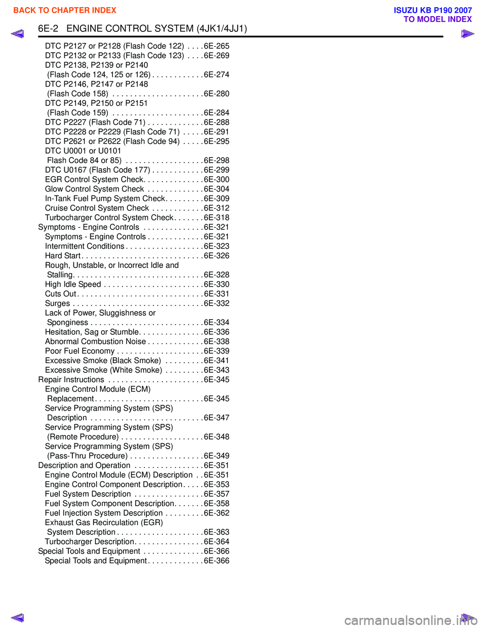
DTC P2127 or P2128 (Flash Code 122) . . . . 6E-265
DTC P2132 or P2133 (Flash Code 123) . . . . 6E-269
DTC P2138, P2139 or P2140 (Flash Code 124, 125 or 126) . . . . . . . . . . . . 6E-274
DTC P2146, P2147 or P2148 (Flash Code 158) . . . . . . . . . . . . . . . . . . . . . 6E-280
DTC P2149, P2150 or P2151 (Flash Code 159) . . . . . . . . . . . . . . . . . . . . . 6E-284
DTC P2227 (Flash Code 71) . . . . . . . . . . . . . 6E-288
DTC P2228 or P2229 (Flash Code 71) . . . . . 6E-291
DTC P2621 or P2622 (Flash Code 94) . . . . . 6E-295
DTC U0001 or U0101 Flash Code 84 or 85) . . . . . . . . . . . . . . . . . . 6E-298
DTC U0167 (Flash Code 177) . . . . . . . . . . . . 6E-299
EGR Control System Check. . . . . . . . . . . . . . 6E-300
Glow Control System Check . . . . . . . . . . . . . 6E-304
In-Tank Fuel Pump System Check . . . . . . . . . 6E-309
Cruise Control System Check . . . . . . . . . . . . 6E-312
Turbocharger Control System Check . . . . . . . 6E-318
Symptoms - Engine Controls . . . . . . . . . . . . . . 6E-321 Symptoms - Engine Controls . . . . . . . . . . . . . 6E-321
Intermittent Conditions . . . . . . . . . . . . . . . . . . 6E-323
Hard Start . . . . . . . . . . . . . . . . . . . . . . . . . . . . 6E-326
Rough, Unstable, or Incorrect Idle and Stalling. . . . . . . . . . . . . . . . . . . . . . . . . . . . . . 6E-328
High Idle Speed . . . . . . . . . . . . . . . . . . . . . . . 6E-330
Cuts Out . . . . . . . . . . . . . . . . . . . . . . . . . . . . . 6E-331
Surges . . . . . . . . . . . . . . . . . . . . . . . . . . . . . . 6E-332
Lack of Power, Sluggishness or Sponginess . . . . . . . . . . . . . . . . . . . . . . . . . . 6E-334
Hesitation, Sag or Stumble. . . . . . . . . . . . . . . 6E-336
Abnormal Combustion Noise . . . . . . . . . . . . . 6E-338
Poor Fuel Economy . . . . . . . . . . . . . . . . . . . . 6E-339
Excessive Smoke (Black Smoke) . . . . . . . . . 6E-341
Excessive Smoke (White Smoke) . . . . . . . . . 6E-343
Repair Instructions . . . . . . . . . . . . . . . . . . . . . . 6E-345 Engine Control Module (ECM) Replacement . . . . . . . . . . . . . . . . . . . . . . . . . 6E-345
Service Programming System (SPS) Description . . . . . . . . . . . . . . . . . . . . . . . . . . 6E-347
Service Programming System (SPS) (Remote Procedure) . . . . . . . . . . . . . . . . . . . 6E-348
Service Programming System (SPS) (Pass-Thru Procedure) . . . . . . . . . . . . . . . . . 6E-349
Description and Operation . . . . . . . . . . . . . . . . 6E-351 Engine Control Module (ECM) Description . . 6E-351
Engine Control Component Description . . . . . 6E-353
Fuel System Description . . . . . . . . . . . . . . . . 6E-357
Fuel System Component Description. . . . . . . 6E-358
Fuel Injection System Description . . . . . . . . . 6E-362
Exhaust Gas Recirculation (EGR) System Description . . . . . . . . . . . . . . . . . . . . 6E-363
Turbocharger Description . . . . . . . . . . . . . . . . 6E-364
Special Tools and Equipment . . . . . . . . . . . . . . 6E-366 Special Tools and Equipment . . . . . . . . . . . . . 6E-366
BACK TO CHAPTER INDEX
TO MODEL INDEX
ISUZU KB P190 2007
Page 1621 of 6020
6E-4 ENGINE CONTROL SYSTEM (4JK1/4JJ1)
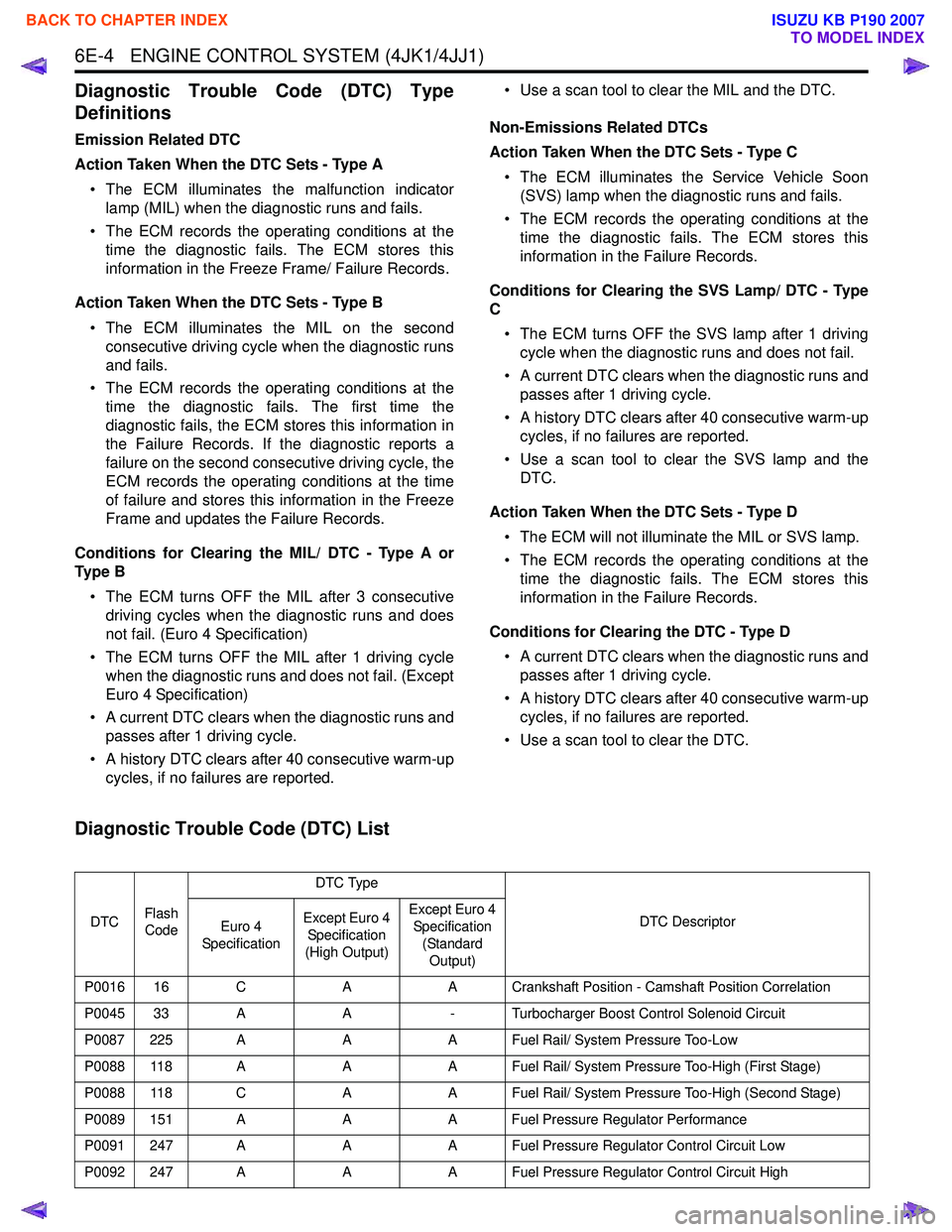
Diagnostic Trouble Code (DTC) Type
Definitions
Emission Related DTC
Action Taken When the DTC Sets - Type A • The ECM illuminates the malfunction indicator lamp (MIL) when the diagnostic runs and fails.
• The ECM records the operating conditions at the time the diagnostic fails. The ECM stores this
information in the Freeze Frame/ Failure Records.
Action Taken When the DTC Sets - Type B • The ECM illuminates the MIL on the second consecutive driving cycle when the diagnostic runs
and fails.
• The ECM records the operating conditions at the time the diagnostic fails. The first time the
diagnostic fails, the ECM stores this information in
the Failure Records. If the diagnostic reports a
failure on the second consecutive driving cycle, the
ECM records the operating conditions at the time
of failure and stores this information in the Freeze
Frame and updates the Failure Records.
Conditions for Clearing the MIL/ DTC - Type A or
Ty p e B
• The ECM turns OFF the MIL after 3 consecutive driving cycles when the diagnostic runs and does
not fail. (Euro 4 Specification)
• The ECM turns OFF the MIL after 1 driving cycle when the diagnostic runs and does not fail. (Except
Euro 4 Specification)
• A current DTC clears when the diagnostic runs and passes after 1 driving cycle.
• A history DTC clears after 40 consecutive warm-up cycles, if no failures are reported. • Use a scan tool to clear the MIL and the DTC.
Non-Emissions Related DTCs
Action Taken When the DTC Sets - Type C
• The ECM illuminates the Service Vehicle Soon (SVS) lamp when the diagnostic runs and fails.
• The ECM records the operating conditions at the time the diagnostic fails. The ECM stores this
information in the Failure Records.
Conditions for Clearing the SVS Lamp/ DTC - Type
C
• The ECM turns OFF the SVS lamp after 1 driving cycle when the diagnostic runs and does not fail.
• A current DTC clears when the diagnostic runs and passes after 1 driving cycle.
• A history DTC clears after 40 consecutive warm-up cycles, if no failures are reported.
• Use a scan tool to clear the SVS lamp and the DTC.
Action Taken When the DTC Sets - Type D • The ECM will not illuminate the MIL or SVS lamp.
• The ECM records the operating conditions at the time the diagnostic fails. The ECM stores this
information in the Failure Records.
Conditions for Clearing the DTC - Type D • A current DTC clears when the diagnostic runs and passes after 1 driving cycle.
• A history DTC clears after 40 consecutive warm-up cycles, if no failures are reported.
• Use a scan tool to clear the DTC.
Diagnostic Trouble Code (DTC) List
DTC Flash
Code DTC Type
DTC Descriptor
Euro 4
Specification Except Euro 4
Specification
(High Output) Except Euro 4
Specification
(Standard Output)
P0016 16 C AA Crankshaft Position - Camshaft Position Correlation
P0045 33 A A- Turbocharger Boost Control Solenoid Circuit
P0087 225 A AA Fuel Rail/ System Pressure Too-Low
P0088 118 A AA Fuel Rail/ System Pressure Too-High (First Stage)
P0088 118 C AA Fuel Rail/ System Pressure Too-High (Second Stage)
P0089 151 A AA Fuel Pressure Regulator Performance
P0091 247 A AA Fuel Pressure Regulator Control Circuit Low
P0092 247 A AA Fuel Pressure Regulator Control Circuit High
BACK TO CHAPTER INDEX
TO MODEL INDEX
ISUZU KB P190 2007
Page 1622 of 6020

ENGINE CONTROL SYSTEM (4JK1/4JJ1) 6E-5
P0093 227 AAA Fuel System Leak Detected
P0101 92 A -- Mass Air Flow Sensor Circuit Range/ Performance
P0102 91 A AA Mass Air Flow Sensor Circuit Low Input
P0103 91 A AA Mass Air Flow Sensor Circuit High Input
P0107 32 A A- Manifold Absolute Pressure Sensor Circuit Low Input
P0108 32 A A- Manifold Absolute Pressure Sensor Circuit High Input
P0112 22 A AA Intake Air Temperature Sensor Circuit Low
P0113 22 A AA Intake Air Temperature Sensor Circuit High
P0116 23 A --Engine Coolant Temperature Sensor Circuit Range/
Performance
P0117 23 A AA Engine Coolant Temperature Sensor Circuit Low
P0118 23 A AA Engine Coolant Temperature Sensor Circuit High
P0122 43 B AA Throttle Position Sensor Circuit Low
P0123 43 B AA Throttle Position Sensor Circuit High
P0182 211 A AA Fuel Temperature Sensor Circuit Low
P0183 211 A AA Fuel Temperature Sensor Circuit High
P0192 245 A AA Fuel Rail Pressure Sensor Circuit Low
P0193 245 A AA Fuel Rail Pressure Sensor Circuit High
P0201 271 A AA Injector Circuit Open - Cylinder 1
P0202 272 A AA Injector Circuit Open - Cylinder 2
P0203 273 A AA Injector Circuit Open - Cylinder 3
P0204 274 A AA Injector Circuit Open - Cylinder 4
P0217 542 D DD Engine Coolant Over Temperature Condition
P0219 543 C AA Engine Overspeed Condition
P0231 69 C AA Fuel Pump Secondary Circuit Low
P0232 69 C AA Fuel Pump Secondary Circuit High
P0234 42 A A- Turbocharger Overboost Condition
P0299 65 A A- Turbocharger Underboost
P0335 15 A AA Crankshaft Position Sensor Circuit
P0336 15 A AA Crankshaft Position Sensor Circuit Range/ Performance
P0340 14 C AA Camshaft Position Sensor Circuit
P0341 14 C AA Camshaft Position Sensor Circuit Range/ Performance
P0380 66 C AA Glow Plug Circuit
P0401 93 A -- EGR Flow Insufficient Detected
P0403 37 B AA EGR Control Circuit
P0404 45 A AA EGR Control Circuit Range/ Performance
P0405 44 B AA EGR Sensor Circuit Low
P0406 44 B AA EGR Sensor Circuit High
P0500 25 A AA Vehicle Speed Sensor
DTC
Flash
Code DTC Type
DTC Descriptor
Euro 4
Specification Except Euro 4
Specification
(High Output) Except Euro 4
Specification (Standard Output)
BACK TO CHAPTER INDEX
TO MODEL INDEX
ISUZU KB P190 2007
Page 1623 of 6020
6E-6 ENGINE CONTROL SYSTEM (4JK1/4JJ1)
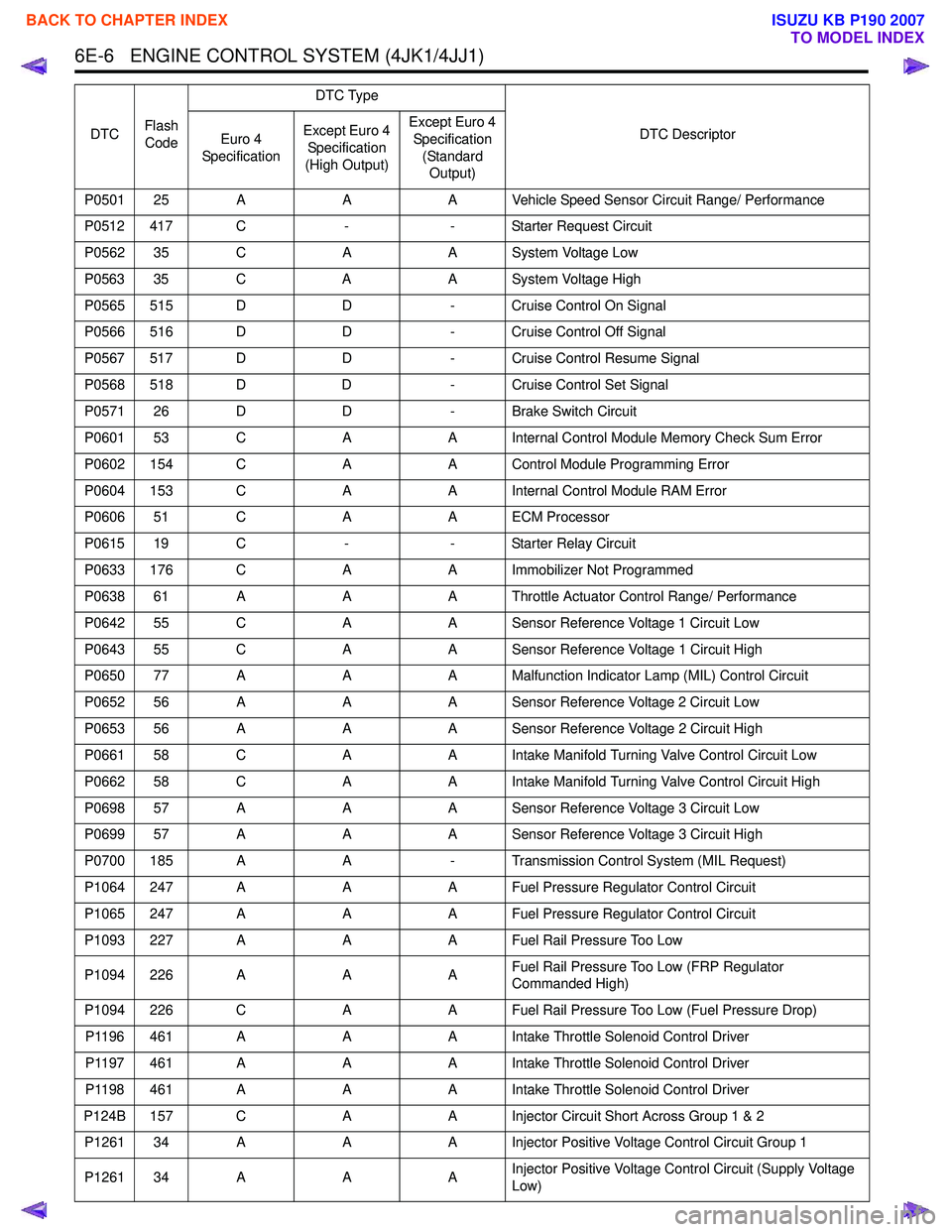
P0501 25 AAA Vehicle Speed Sensor Circuit Range/ Performance
P0512 417 C -- Starter Request Circuit
P0562 35 C AA System Voltage Low
P0563 35 C AA System Voltage High
P0565 515 D D- Cruise Control On Signal
P0566 516 D D- Cruise Control Off Signal
P0567 517 D D- Cruise Control Resume Signal
P0568 518 D D- Cruise Control Set Signal
P0571 26 D D- Brake Switch Circuit
P0601 53 C AA Internal Control Module Memory Check Sum Error
P0602 154 C AA Control Module Programming Error
P0604 153 C AA Internal Control Module RAM Error
P0606 51 C AA ECM Processor
P0615 19 C -- Starter Relay Circuit
P0633 176 C AA Immobilizer Not Programmed
P0638 61 A AA Throttle Actuator Control Range/ Performance
P0642 55 C AA Sensor Reference Voltage 1 Circuit Low
P0643 55 C AA Sensor Reference Voltage 1 Circuit High
P0650 77 A AA Malfunction Indicator Lamp (MIL) Control Circuit
P0652 56 A AA Sensor Reference Voltage 2 Circuit Low
P0653 56 A AA Sensor Reference Voltage 2 Circuit High
P0661 58 C AA Intake Manifold Turning Valve Control Circuit Low
P0662 58 C AA Intake Manifold Turning Valve Control Circuit High
P0698 57 A AA Sensor Reference Voltage 3 Circuit Low
P0699 57 A AA Sensor Reference Voltage 3 Circuit High
P0700 185 A A- Transmission Control System (MIL Request)
P1064 247 A AA Fuel Pressure Regulator Control Circuit
P1065 247 A AA Fuel Pressure Regulator Control Circuit
P1093 227 A AA Fuel Rail Pressure Too Low
P1094 226 A AAFuel Rail Pressure Too Low (FRP Regulator
Commanded High)
P1094 226 C AA Fuel Rail Pressure Too Low (Fuel Pressure Drop)
P1196 461 A AA Intake Throttle Solenoid Control Driver
P1197 461 A AA Intake Throttle Solenoid Control Driver
P1198 461 A AA Intake Throttle Solenoid Control Driver
P124B 157 C AA Injector Circuit Short Across Group 1 & 2
P1261 34 A AA Injector Positive Voltage Control Circuit Group 1
P1261 34 A AAInjector Positive Voltage Control Circuit (Supply Voltage
Low)
DTC
Flash
Code DTC Type
DTC Descriptor
Euro 4
Specification Except Euro 4
Specification
(High Output) Except Euro 4
Specification (Standard Output)
BACK TO CHAPTER INDEX
TO MODEL INDEX
ISUZU KB P190 2007
Page 1624 of 6020
ENGINE CONTROL SYSTEM (4JK1/4JJ1) 6E-7
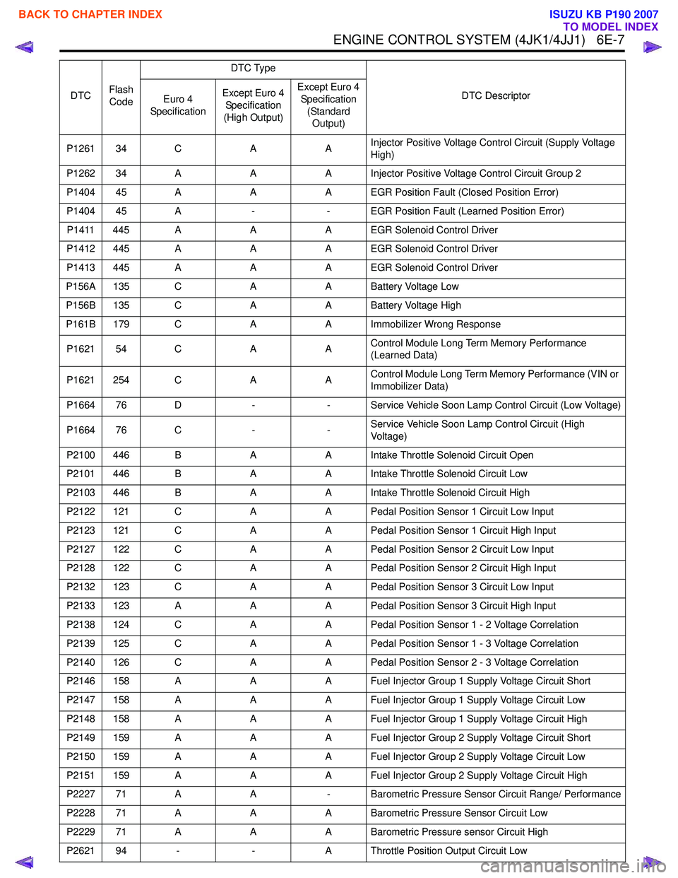
P1261 34 CAAInjector Positive Voltage Control Circuit (Supply Voltage
High)
P1262 34 A AA Injector Positive Voltage Control Circuit Group 2
P1404 45 A AA EGR Position Fault (Closed Position Error)
P1404 45 A -- EGR Position Fault (Learned Position Error)
P1411 445 A AA EGR Solenoid Control Driver
P1412 445 A AA EGR Solenoid Control Driver
P1413 445 A AA EGR Solenoid Control Driver
P156A 135 C AA Battery Voltage Low
P156B 135 C AA Battery Voltage High
P161B 179 C AA Immobilizer Wrong Response
P1621 54 C AAControl Module Long Term Memory Performance
(Learned Data)
P1621 254 C AAControl Module Long Term Memory Performance (VIN or
Immobilizer Data)
P1664 76 D -- Service Vehicle Soon Lamp Control Circuit (Low Voltage)
P1664 76 C --Service Vehicle Soon Lamp Control Circuit (High
Voltage)
P2100 446 B AA Intake Throttle Solenoid Circuit Open
P2101 446 B AA Intake Throttle Solenoid Circuit Low
P2103 446 B AA Intake Throttle Solenoid Circuit High
P2122 121 C AA Pedal Position Sensor 1 Circuit Low Input
P2123 121 C AA Pedal Position Sensor 1 Circuit High Input
P2127 122 C AA Pedal Position Sensor 2 Circuit Low Input
P2128 122 C AA Pedal Position Sensor 2 Circuit High Input
P2132 123 C AA Pedal Position Sensor 3 Circuit Low Input
P2133 123 A AA Pedal Position Sensor 3 Circuit High Input
P2138 124 C AA Pedal Position Sensor 1 - 2 Voltage Correlation
P2139 125 C AA Pedal Position Sensor 1 - 3 Voltage Correlation
P2140 126 C AA Pedal Position Sensor 2 - 3 Voltage Correlation
P2146 158 A AA Fuel Injector Group 1 Supply Voltage Circuit Short
P2147 158 A AA Fuel Injector Group 1 Supply Voltage Circuit Low
P2148 158 A AA Fuel Injector Group 1 Supply Voltage Circuit High
P2149 159 A AA Fuel Injector Group 2 Supply Voltage Circuit Short
P2150 159 A AA Fuel Injector Group 2 Supply Voltage Circuit Low
P2151 159 A AA Fuel Injector Group 2 Supply Voltage Circuit High
P2227 71 A A- Barometric Pressure Sensor Circuit Range/ Performance
P2228 71 A AA Barometric Pressure Sensor Circuit Low
P2229 71 A AA Barometric Pressure sensor Circuit High
P2621 94 - -A Throttle Position Output Circuit Low
DTC
Flash
Code DTC Type
DTC Descriptor
Euro 4
Specification Except Euro 4
Specification
(High Output) Except Euro 4
Specification (Standard Output)
BACK TO CHAPTER INDEX
TO MODEL INDEX
ISUZU KB P190 2007
Page 1625 of 6020
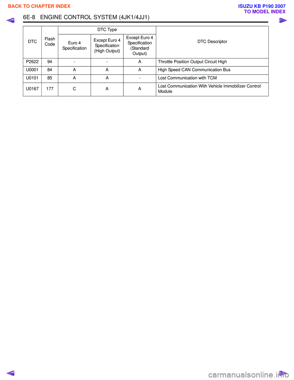
6E-8 ENGINE CONTROL SYSTEM (4JK1/4JJ1)
P2622 94 --A Throttle Position Output Circuit High
U0001 84 A AA High Speed CAN Communication Bus
U0101 85 A A- Lost Communication with TCM
U0167 177 C AALost Communication With Vehicle Immobilizer Control
Module
DTC
Flash
Code DTC Type
DTC Descriptor
Euro 4
Specification Except Euro 4
Specification
(High Output) Except Euro 4
Specification (Standard Output)
BACK TO CHAPTER INDEX
TO MODEL INDEX
ISUZU KB P190 2007
Page 1661 of 6020
6E-44 ENGINE CONTROL SYSTEM (4JK1/4JJ1)
Diagnostic Starting Point - Engine Controls
Begin the system diagnosis with Diagnostic System
Check - Engine Controls. The Diagnostic System
Check - Engine Controls will provide the following
information:
• The identification of the control modules which command the system.
• The ability of the control modules to communicate through the serial data circuit.
• The identification of any stored diagnostic trouble codes (DTCs) and the their statuses.
The use of the Diagnostic System Check - Engine
Controls will identify the correct procedure for
diagnosing the system and where the procedure is
located.
Important: Engine Control System Check Sheet must
be used to verify the complaint vehicle, you need to
know the correct (normal) operating behavior of the
system and verify that the customer complaint is a valid
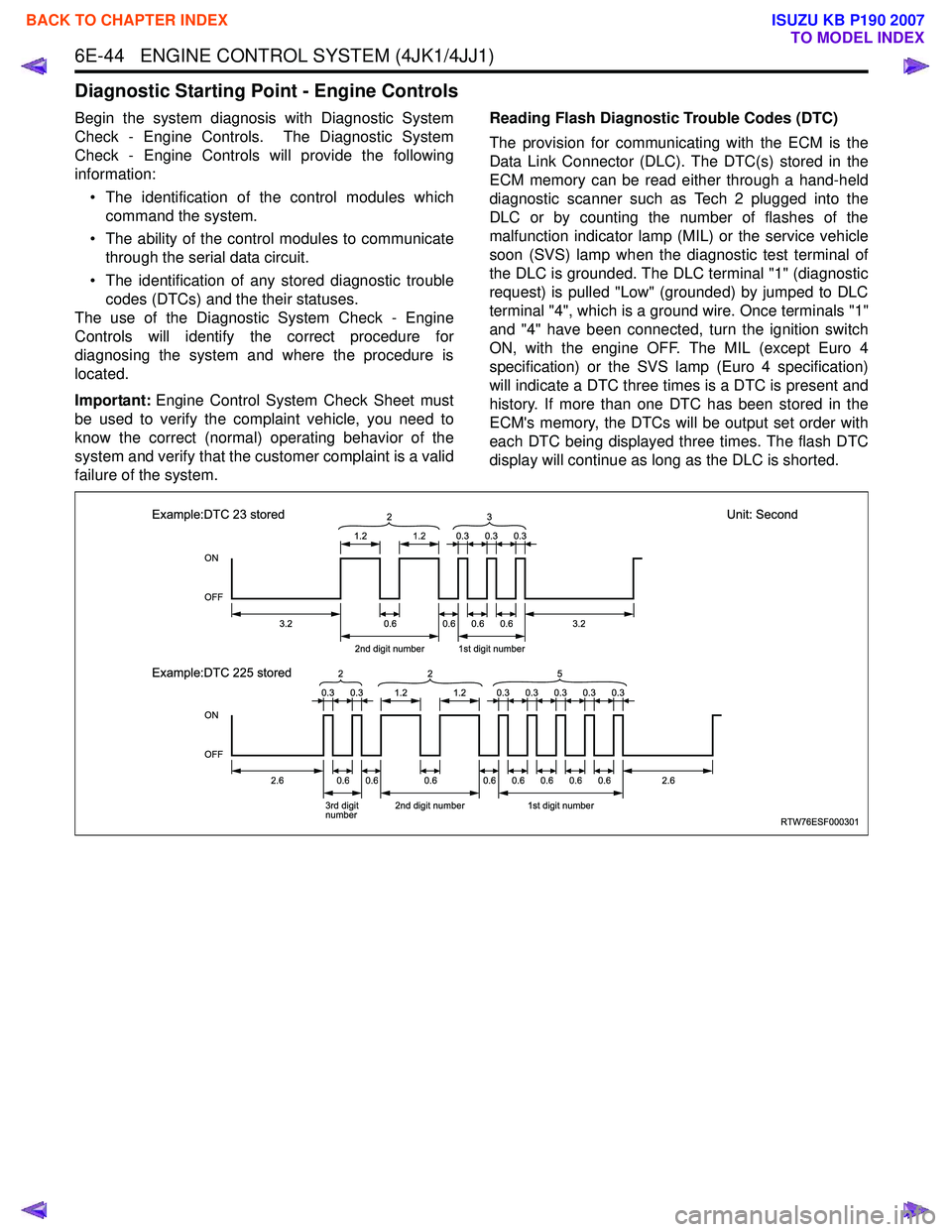
failure of the system. Reading Flash Diagnostic Trouble Codes (DTC)
The provision for communicating with the ECM is the
Data Link Connector (DLC). The DTC(s) stored in the
ECM memory can be read either through a hand-held
diagnostic scanner such as Tech 2 plugged into the
DLC or by counting the number of flashes of the
malfunction indicator lamp (MIL) or the service vehicle
soon (SVS) lamp when the diagnostic test terminal of
the DLC is grounded. The DLC terminal "1" (diagnostic
request) is pulled "Low" (grounded) by jumped to DLC
terminal "4", which is a ground wire. Once terminals "1"
and "4" have been connected, turn the ignition switch
ON, with the engine OFF. The MIL (except Euro 4
specification) or the SVS lamp (Euro 4 specification)
will indicate a DTC three times is a DTC is present and
history. If more than one DTC has been stored in the
ECM's memory, the DTCs will be output set order with
each DTC being displayed three times. The flash DTC
display will continue as long as the DLC is shorted.
RTW76ESF000301
ON
OFF
ON
OFF
1.2
3.2
2.62.6
2nd digit number1st digit number
3.20.6 2
1.2
0.60.60.6
0.30.30.3
0.30.30.30.30.3
Example:DTC 23 stored
Unit: Second
Example:DTC 225 stored
3rd digit
number 2nd digit number1st digit number
0.60.60.60.60.60.60.60.6
3
0.30.31.21.2
2
25
BACK TO CHAPTER INDEX
TO MODEL INDEX
ISUZU KB P190 2007
Page 1686 of 6020
ENGINE CONTROL SYSTEM (4JK1/4JJ1) 6E-69
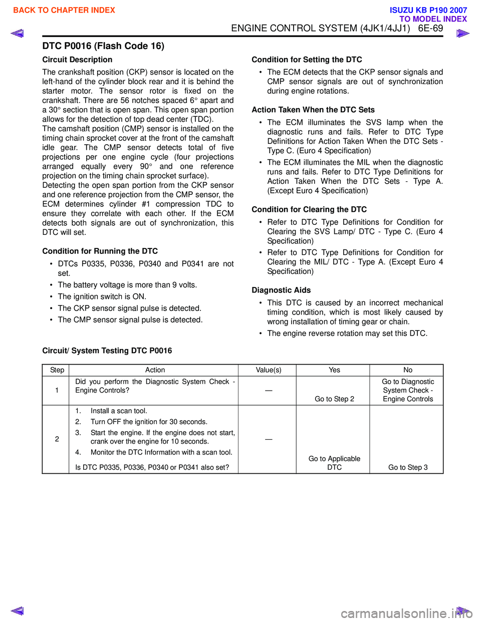
DTC P0016 (Flash Code 16)
Circuit Description
The crankshaft position (CKP) sensor is located on the
left-hand of the cylinder block rear and it is behind the
starter motor. The sensor rotor is fixed on the
crankshaft. There are 56 notches spaced 6 ° apart and
a 30 ° section that is open span. This open span portion
allows for the detection of top dead center (TDC).
The camshaft position (CMP) sensor is installed on the
timing chain sprocket cover at the front of the camshaft
idle gear. The CMP sensor detects total of five
projections per one engine cycle (four projections
arranged equally every 90 ° and one reference
projection on the timing chain sprocket surface).
Detecting the open span portion from the CKP sensor
and one reference projection from the CMP sensor, the
ECM determines cylinder #1 compression TDC to
ensure they correlate with each other. If the ECM
detects both signals are out of synchronization, this
DTC will set.
Condition for Running the DTC • DTCs P0335, P0336, P0340 and P0341 are not set.
• The battery voltage is more than 9 volts.
• The ignition switch is ON.
• The CKP sensor signal pulse is detected.
• The CMP sensor signal pulse is detected. Condition for Setting the DTC
• The ECM detects that the CKP sensor signals and CMP sensor signals are out of synchronization
during engine rotations.
Action Taken When the DTC Sets • The ECM illuminates the SVS lamp when the diagnostic runs and fails. Refer to DTC Type
Definitions for Action Taken When the DTC Sets -
Type C. (Euro 4 Specification)
• The ECM illuminates the MIL when the diagnostic runs and fails. Refer to DTC Type Definitions for
Action Taken When the DTC Sets - Type A.
(Except Euro 4 Specification)
Condition for Clearing the DTC • Refer to DTC Type Definitions for Condition for Clearing the SVS Lamp/ DTC - Type C. (Euro 4
Specification)
• Refer to DTC Type Definitions for Condition for Clearing the MIL/ DTC - Type A. (Except Euro 4
Specification)
Diagnostic Aids • This DTC is caused by an incorrect mechanical timing condition, which is most likely caused by
wrong installation of timing gear or chain.
• The engine reverse rotation may set this DTC.
Circuit/ System Testing DTC P0016
Step Action Value(s)Yes No
1 Did you perform the Diagnostic System Check -
Engine Controls? —
Go to Step 2 Go to Diagnostic
System Check -
Engine Controls
2 1. Install a scan tool.
2. Turn OFF the ignition for 30 seconds.
3. Start the engine. If the engine does not start, crank over the engine for 10 seconds.
4. Monitor the DTC Information with a scan tool.
Is DTC P0335, P0336, P0340 or P0341 also set? —
Go to Applicable DTC Go to Step 3
BACK TO CHAPTER INDEX
TO MODEL INDEX
ISUZU KB P190 2007
Page 1688 of 6020

ENGINE CONTROL SYSTEM (4JK1/4JJ1) 6E-71
DTC P0045 (Flash Code 33)
Circuit Description
The position of the turbocharger nozzle is controlled by
the ECM. The ECM utilizes a turbocharger nozzle
control solenoid valve and a boost pressure sensor to
control the turbocharger nozzles. When the engine is
not under load, the turbocharger nozzles are in an open
position, or no boost condition. When the engine is
under load, the ECM commands the control solenoid
valve to close the turbocharger nozzles, thus
increasing the boost. The ECM will vary the boost
dependant upon the load requirements of the engine.
The ECM uses a pulse width modulation (PWM) on the
control circuit to open and control the solenoid valve. If
the ECM detects an open circuit or short circuit on the
solenoid valve circuit, this DTC will set.
Condition for Running the DTC • The ignition switch is ON.
Condition for Setting the DTC
Either of following condition is met: • The ECM detects a low voltage condition on the turbocharger nozzle control solenoid circuit when
the solenoid is commanded OFF.
• The ECM detects a high voltage condition on the turbocharger nozzle control solenoid circuit when
the solenoid is commanded ON. Action Taken When the DTC Sets
• The ECM illuminates the MIL when the diagnostic runs and fails. Refer to DTC Type Definitions for
Action Taken When the DTC Sets - Type A.
• The ECM limits fuel injection quantity.
• The ECM inhibits pilot injection.
• The ECM inhibits cruise control.
Condition for Clearing the DTC • Refer to DTC Type Definitions for Condition for Clearing the MIL/ DTC - Type A.
Diagnostic Aids • If an intermittent condition is suspected, refer to Intermittent Conditions in this section.
Test description
The number below refers to the step number on the
Circuit/ System Testing.
4. If the solenoid control circuit between the ECM and
the solenoid is normal, the test lamp changes from
Bright to Dim when commanded from Increase to
Decrease.
Schematic Reference: Vacuum Hose Routing
Diagram and Engine Controls Schematics
Connector End View Reference: Engine Controls
Connector End Views or ECM Connector End Views
Circuit/ System Testing DTC P0045
Step Action Value(s)Yes No
1 Did you perform the Diagnostic System Check -
Engine Controls? —
Go to Step 2 Go to Diagnostic
System Check -
Engine Controls
2 1. Install a scan tool.
2. Turn OFF the ignition for 30 seconds.
3. Start the engine.
4. Monitor the DTC Information with a scan tool.
Does the DTC fail this ignition? —
Go to Step 3 Go to Diagnostic
Aids
3 1. Turn OFF the ignition.
2. Disconnect the turbocharger nozzle control solenoid valve harness connector.
3. Connect a test lamp between the ignition voltage feed circuit (pin 2 of E-106) and a
known good ground.
4. Turn ON the ignition, with the engine OFF.
Does the test lamp illuminate? —
Go to Step 4 Go to Step 5
BACK TO CHAPTER INDEX
TO MODEL INDEX
ISUZU KB P190 2007