engine coolant ISUZU KB P190 2007 Workshop Repair Manual
[x] Cancel search | Manufacturer: ISUZU, Model Year: 2007, Model line: KB P190, Model: ISUZU KB P190 2007Pages: 6020, PDF Size: 70.23 MB
Page 1981 of 6020

6E-364 ENGINE CONTROL SYSTEM (4JK1/4JJ1)
Fuel Injection System Description
Fuel Injection Quantity Control
This control determines the fuel injection quantity by
adding coolant temperature, fuel temperature, intake
air temperature, barometric pressure, mass air flow and
some switch inputs information corrections to the basic
injection quantity is calculated by the ECM based on
the engine operating conditions (engine speed,
accelerator pedal pressing amount and boost pressure
sensor). More fuel rate indicates if the engine load is
increased as the accelerator pedal is stepped on at
constant engine speed.
Combined with high pressure injection of atomized fuel,
this control improves exhaust gas and ensures proper
fuel consumption. Compared with conventional
mechanical governors, an electronic control system
provides higher degree of freedom of fuel injection
quantity control, thereby presenting high accelerator
response (acceleration feeling and pressing feeling).
Starting Injection Quantity Control
At the engine starting (after the key switch is turned to
the START position to start the engine, up to return of
key switch to the ON position), optimum fuel injection
quantity is controlled based on the information on the
engine speed and coolant temperature. At low
temperature, the fuel injection quantity increases.
When the engine started completely, this boosted
quantity mode at the starting is cancelled and normal
running mode is restored.
Idle Speed Control
A control is made so as to achieve stable idling speed
at all time regardless of engine secular changes or
engine condition variations. The ECM sets target idling
speed and controls the fuel injection quantity according
to the engine conditions (actual engine speed, coolant
temperature and engine load) to follow actual engine
speed to the target idling speed so as to ensure stable
idling speed.
Idle Vibration Control
A control is made so as to reduce the engine vibration
caused by torque variations between cylinders due to
variations in fuel injection quantity of each cylinder or
injector performance. The ECM corrects the injection
quantity between cylinders based on the revolution
signals from the crankshaft position (CKP) sensor.
Normal range of correction quantity between cylinders
is within ±5 mm
3.
BACK TO CHAPTER INDEX
TO MODEL INDEX
ISUZU KB P190 2007
Page 1982 of 6020

ENGINE CONTROL SYSTEM (4JK1/4JJ1) 6E-365
Exhaust Gas Recirculation (EGR) System Description
Legend1. EGR cooler
2. Engine coolant outlet
3. Engine coolant inlet
4. EGR valve 5. ECM
6. MAF sensor
7. Intake throttle valve
The EGR system recirculates a part of exhaust gas
back into the intake manifold, which results in reducing
nitrogen oxide (NOx) emissions. The EGR control
system uses an electronic control system to ensure
both driveability and low emission. A control current
from the ECM operates a solenoid to control the lift
amount of EGR valve. Also, an EGR position sensor is
provided at the rear of the motor to feed actual valve lift
amount back to the ECM for more precision control of
the EGR amount.
The EGR control starts when the conditions for engine
speed, engine coolant temperature, intake air
temperature and barometric pressure are satisfied.
Then, the valve opening is calculated according to the
engine speed, and target fuel injection quantity. Based
on this valve opening, the drive duty of the solenoid is
determined and the valve is driven accordingly. The
intake throttle valve is provided to adequate intake
manifold depression to ensure EGR gas flow. EGR Valve
RTW56EMF001701
1
4
7 5
6
23
RTW56ESH000801
BACK TO CHAPTER INDEX
TO MODEL INDEX
ISUZU KB P190 2007
Page 1994 of 6020

EXHAUST SYSTEM (4JK1/4JJ1) 6F-9
Removal
1. Drain the coolant.
2. Remove the intercooler.
3. Remove the heat protector.
4. Disconnect the water hoses from the EGR coole
r
water pipes.
5. Remove the EGR cooler.
Installation (Standard Output)
1. Gasket
2. EGR Cooler
3. Nuts and Bolts
RTW 56FSH000201
• Temporary tightening order
1 – 2 – 4 – 5 - 3
• Fully tightening order
4 – 5 – 1 – 2 - 3
Tighten the nuts and bolts to the specified torque.
Tightening torque: 27 N ⋅
⋅⋅
⋅
m (2.8 kg ⋅
⋅⋅
⋅
m / 20 lb ft)
4. W ater hose
5. Heat protector • Tighten the bolts to the specified torque.
Tightening torque: 10 N ⋅
⋅⋅
⋅
m (1.0 kg ⋅
⋅⋅
⋅
m / 87 lb in)
RTW 56ASH014601
6. Replenish the engine coolant.
BACK TO CHAPTER INDEX
TO MODEL INDEX
ISUZU KB P190 2007
Page 1995 of 6020

6F-10 EXHAUST SYSTEM (4JK1/4JJ1)
Installation (High Output)
1. Gasket
2. EGR Cooler
3. Nuts and Bolts
6
543
1
2
RTW 76FSH000201
• Temporary tightening order
1 →2→ 3→ 4→ 5→ 6
• Fully tightening order
3 →4→ 5→ 1→ 2→ 6
Tighten the nuts and bolts to the specified torque.
Tightening torque: Nuts and bolts 1-5: 27 N ⋅
⋅⋅
⋅
m (2.8 kg ⋅
⋅⋅
⋅
m / 20 lb ft)
Bolt 6: 52 N⋅
⋅⋅
⋅
m (5.3 kg ⋅
⋅⋅
⋅
m / 38 lb ft)
4. W ater hose
5. Heat protector • Tighten the bolts to the specified torque.
Tightening torque: 25 N ⋅
⋅⋅
⋅
m (2.5 kg ⋅
⋅⋅
⋅
m / 18 lb ft)
RTW 76FSH000101
6. Replenish the engine coolant.
BACK TO CHAPTER INDEX
TO MODEL INDEX
ISUZU KB P190 2007
Page 2004 of 6020

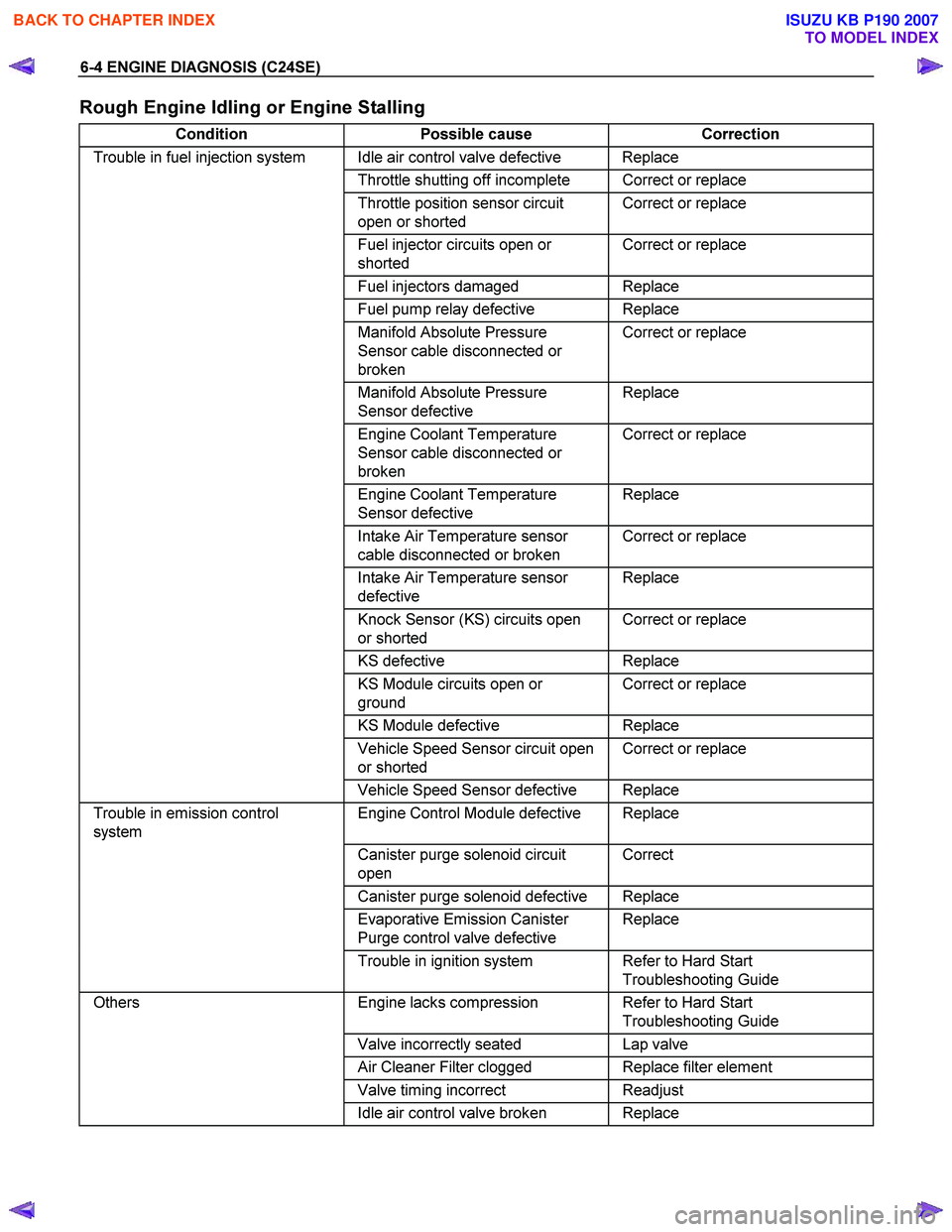
6-4 ENGINE DIAGNOSIS (C24SE)
Rough Engine Idling or Engine Stalling
Condition Possible cause Correction
Trouble in fuel injection system Idle air control valve defective Replace
Throttle shutting off incomplete Correct or replace
Throttle position sensor circuit
open or shorted Correct or replace
Fuel injector circuits open or
shorted Correct or replace
Fuel injectors damaged Replace
Fuel pump relay defective Replace
Manifold Absolute Pressure
Sensor cable disconnected or
broken Correct or replace
Manifold Absolute Pressure
Sensor defective Replace
Engine Coolant Temperature
Sensor cable disconnected or
broken Correct or replace
Engine Coolant Temperature
Sensor defective Replace
Intake Air Temperature sensor
cable disconnected or broken Correct or replace
Intake Air Temperature sensor
defective Replace
Knock Sensor (KS) circuits open
or shorted Correct or replace
KS
defective Replace
KS Module circuits open or
ground Correct or replace
KS Module defective Replace
Vehicle Speed Sensor circuit open
or shorted Correct or replace
Vehicle Speed Sensor defective Replace
Trouble in emission control
system Engine Control Module defective Replace
Canister purge solenoid circuit
open Correct
Canister purge solenoid defective Replace
Evaporative Emission Canister
Purge control valve defective Replace
Trouble in ignition system Refer to Hard Start
Troubleshooting Guide
Others Engine lacks compression Refer to Hard Start
Troubleshooting Guide
Valve incorrectly seated Lap valve
Air Cleaner Filter clogged Replace filter element
Valve timing incorrect Readjust
Idle air control valve broken Replace
BACK TO CHAPTER INDEX
TO MODEL INDEX
ISUZU KB P190 2007
Page 2005 of 6020

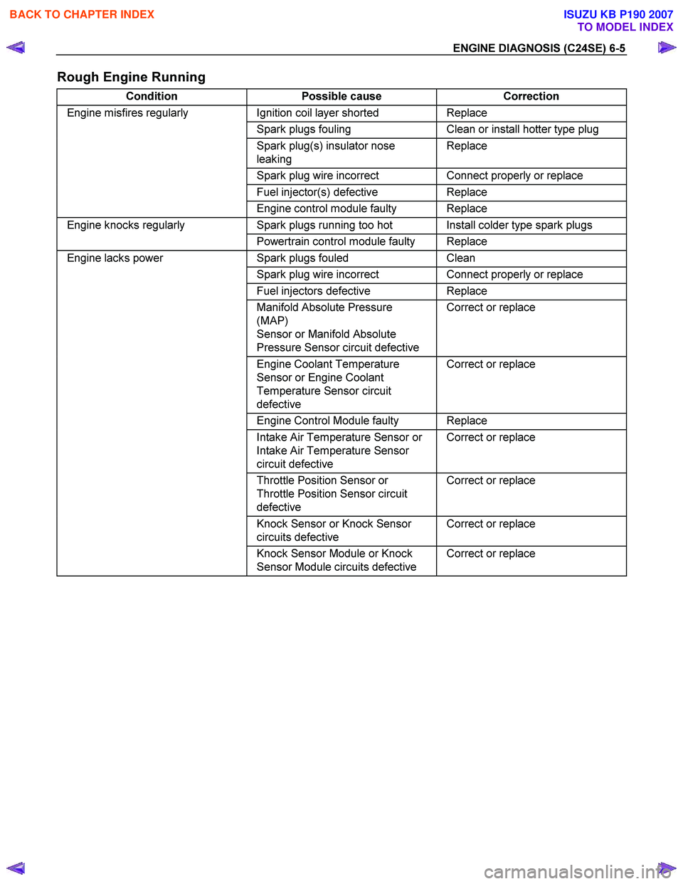
ENGINE DIAGNOSIS (C24SE) 6-5
Rough Engine Running
Condition Possible cause Correction
Engine misfires regularly Ignition coil layer shorted Replace
Spark plugs fouling Clean or install hotter type plug
Spark plug(s) insulator nose
leaking Replace
Spark plug wire incorrect Connect properly or replace
Fuel injector(s) defective Replace
Engine control module faulty Replace
Engine knocks regularly Spark plugs running too hot Install colder type spark plugs
Powertrain control module faulty Replace
Engine lacks power Spark plugs fouled Clean
Spark plug wire incorrect Connect properly or replace
Fuel injectors defective Replace
Manifold Absolute Pressure
(MAP)
Sensor or Manifold Absolute
Pressure Sensor circuit defective Correct or replace
Engine Coolant Temperature
Sensor or Engine Coolant
Temperature Sensor circuit
defective Correct or replace
Engine Control Module faulty Replace
Intake Air Temperature Sensor or
Intake Air Temperature Sensor
circuit defective Correct or replace
Throttle Position Sensor or
Throttle Position Sensor circuit
defective Correct or replace
Knock Sensor or Knock Sensor
circuits defective Correct or replace
Knock Sensor Module or Knock
Sensor Module circuits defective Correct or replace
BACK TO CHAPTER INDEX
TO MODEL INDEX
ISUZU KB P190 2007
Page 2006 of 6020

6-6 ENGINE DIAGNOSIS (C24SE)
Hesitation
Condition Possible cause Correction
Hesitation on acceleration Throttle Position Sensor
adjustment incorrect Replace throttle valve assembly
Throttle Position Sensor circuit
open or shorted Correct or replace
Excessive play in accelerator
linkage Adjust or replace
Manifold Absolute Pressure
(MAP) Sensor circuit open or
shorted Correct or replace
MAP Sensor defective Replace
Intake Air Temperature (IAT)
Sensor circuit open or shorted Correct or replace
Knock Sensor (KS) Circuit open or
shorted Correct or replace
KS
defective Replace
KS Module circuits open or
shorted Correct or replace
KS Module defective Replace
IAT Sensor defective Replace
Hesitation at high speeds
(Fuel pressure too low) Fuel tank strainer clogged Clean or replace
Fuel pipe clogged Clean or replace
Fuel filter clogged Replace
Defective fuel pump system Check and replace
Fuel Pressure Control Valve
leaking Replace
Hesitation at high speeds
(Fuel injector not working
normally) Power supply or ground circuit for
Multiport Fuel Injection System
shorted or open Check and correct or replace
Cable of Multiport Fuel Injection
System disconnected or defective Correct or replace
Hesitation at high speeds
Engine Control Module defective Replace
Throttle Position Sensor circuit
open or shorted Correct or replace
Throttle Position Sensor defective Replace
Engine Coolant Temperature
Sensor circuit open or shorted Correct or replace
Engine Coolant Temperature
Sensor defective Replace
MAP Sensor cable open or
shorted Correct or replace
MAP Sensor defective Replace
IAT Sensor circuit open or shorted Correct or replace
IAT Sensor defective Replace
KS Circuit open or shorted Correct or replace
KS defective Replace
KS Module circuit open or shorted Correct or replace
KS Module defective Replace
Throttle valve not wide opened Check and correct or replace
Air Cleaner Filter clogged Replace filter element
Power supply voltage too low Check and correct or replace
BACK TO CHAPTER INDEX
TO MODEL INDEX
ISUZU KB P190 2007
Page 2007 of 6020

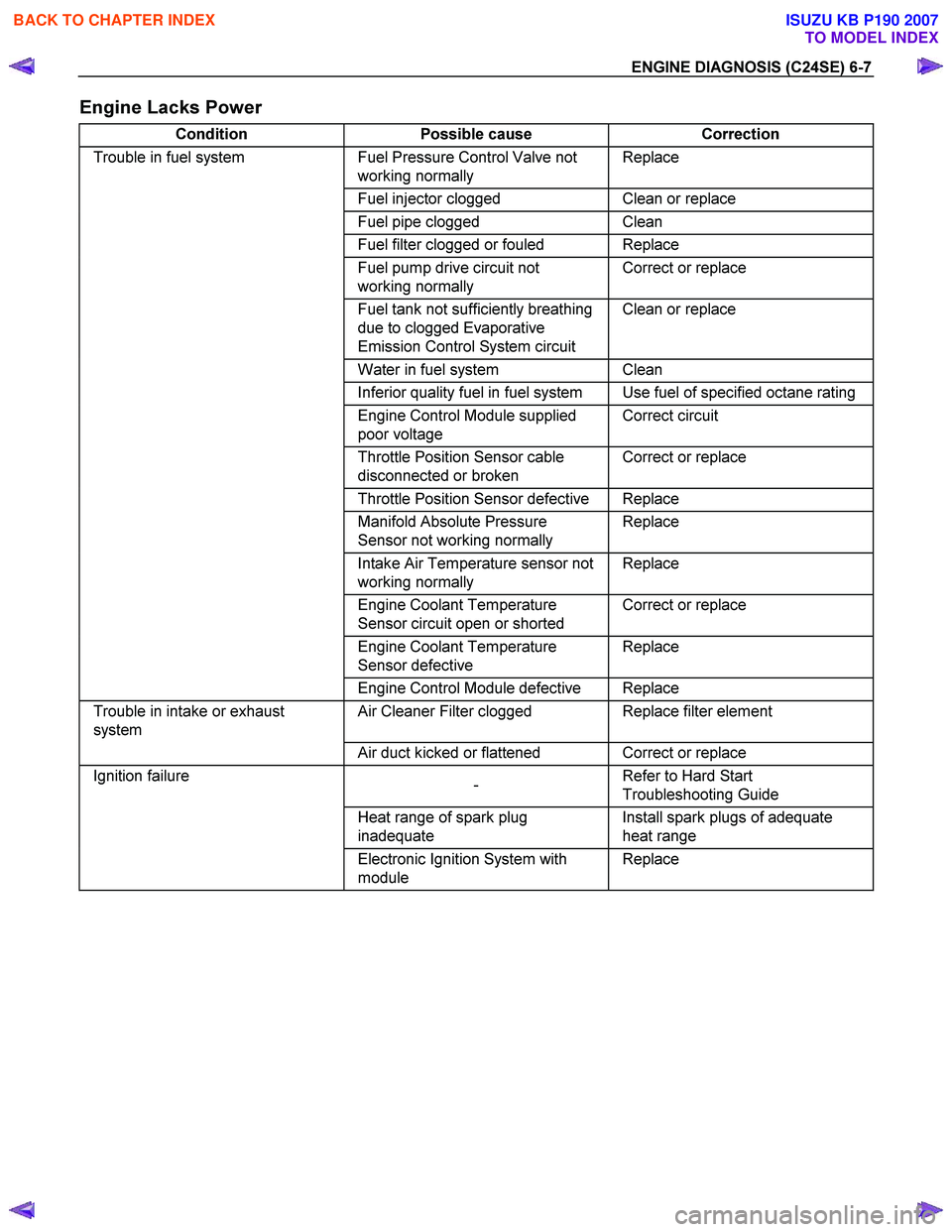
ENGINE DIAGNOSIS (C24SE) 6-7
Engine Lacks Power
Condition Possible cause Correction
Trouble in fuel system Fuel Pressure Control Valve not
working normally Replace
Fuel injector clogged Clean or replace
Fuel pipe clogged Clean
Fuel filter clogged or fouled Replace
Fuel pump drive circuit not
working normally Correct or replace
Fuel tank not sufficiently breathing
due to clogged Evaporative
Emission Control System circuit Clean or replace
Water in fuel system Clean
Inferior quality fuel in fuel system Use fuel of specified octane rating
Engine Control Module supplied
poor voltage Correct circuit
Throttle Position Sensor cable
disconnected or broken Correct or replace
Throttle Position Sensor defective Replace
Manifold Absolute Pressure
Sensor not working normally Replace
Intake Air Temperature sensor not
working normally Replace
Engine Coolant Temperature
Sensor circuit open or shorted Correct or replace
Engine Coolant Temperature
Sensor defective Replace
Engine Control Module defective Replace
Trouble in intake or exhaust
system Air Cleaner Filter clogged Replace filter element
Air duct kicked or flattened Correct or replace
Ignition failure
- Refer to Hard Start
Troubleshooting Guide
Heat range of spark plug
inadequate Install spark plugs of adequate
heat range
Electronic Ignition System with
module Replace
BACK TO CHAPTER INDEX
TO MODEL INDEX
ISUZU KB P190 2007
Page 2008 of 6020

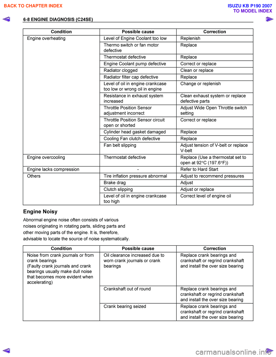
6-8 ENGINE DIAGNOSIS (C24SE)
Condition Possible cause Correction
Engine overheating Level of Engine Coolant too low Replenish
Thermo switch or fan motor
defective Replace
Thermostat
defective Replace
Engine Coolant pump defective Correct or replace
Radiator clogged Clean or replace
Radiator filter cap defective Replace
Level of oil in engine crankcase
too low or wrong oil in engine Change or replenish
Resistance in exhaust system
increased Clean exhaust system or replace
defective parts
Throttle Position Sensor
adjustment incorrect Adjust Wide Open Throttle switch
setting
Throttle Position Sensor circuit
open or shorted Correct or replace
Cylinder head gasket damaged Replace
Cooling Fan clutch defective Replace
Fan belt slipping Adjust tension of V-belt or replace
V-belt
Engine overcooling Thermostat defective Replace (Use a thermostat set to
open at 92 °C (197.6 °F))
Engine lacks compression - Refer to Hard Start
Others Tire inflation pressure abnormal Adjust to recommend pressures
Brake drag Adjust
Clutch slipping Adjust or replace
Level of oil in engine crankcase
too high Correct level of engine oil
Engine Noisy
Abnormal engine noise often consists of various
noises originating in rotating parts, sliding parts and
other moving parts of the engine. It is, therefore,
advisable to locate the source of noise systematically.
Condition Possible cause Correction
Noise from crank journals or from
crank bearings
(Faulty crank journals and crank
bearings usually make dull noise
that becomes more evident when
accelerating) Oil clearance increased due to
worn crank journals or crank
bearings Replace crank bearings and
crankshaft or regrind crankshaft
and install the over size bearing
Crankshaft out of round Replace crank bearings and
crankshaft or regrind crankshaft
and install the over size bearing
Crank bearing seized Replace crank bearings and
crankshaft or regrind crankshaft
and install the over size bearing
BACK TO CHAPTER INDEX
TO MODEL INDEX
ISUZU KB P190 2007
Page 2011 of 6020

ENGINE DIAGNOSIS (C24SE) 6-11
Abnormal Combustion
Condition Possible cause Correction
Trouble in fuel injection system Fuel pressure control valve
defective Replace
Fuel filter clogged Replace
Fuel pump clogged Clean or replace
Fuel tank or fuel pipe clogged Clean or replace
Fuel injector clogged Clean or replace
Fuel pump relay defective Replace
Power supply cable for fuel pump
loosely connected or defective Reconnect, correct or replace
Manifold Absolute Pressure
Sensor circuit open or shorted Correct or replace
Manifold Absolute Pressure
Sensor defective Replace
Engine Coolant Temperature
(ECT) Sensor circuit open or
shorted Correct or replace
ECT Sensor defective Replace
Throttle Position Sensor
adjustment incorrect Reconnect
Throttle Position Sensor defective Replace
Throttle Position Sensor
connector loosely connected Reconnect
Vehicle Speed Sensor cable
loosely connected or defective Correct or replace
Vehicle Speed Sensor loosely
fixed Fix tightly
Vehicle Speed Sensor in wrong
contact or defective Replace
Engine Control Module cable
loosely connected or defective Correct or replace
Trouble in emission control
system Heated Oxygen Sensor circuit
open (If applicable) Correct or replace
Heated Oxygen Sensor defective
(If applicable) Replace
Signal vacuum hose loosely fitted
or defective Correct or replace
ECT Sensor circuit open or
shorted Correct or replace
ECT Sensor defective Replace
Evaporative Emission Control
system (If applicable) Refer to Section 6E
Trouble in ignition system
- Refer to "Engine Lacks Power"
Trouble in cylinder head parts Carbon deposits in combustion
chamber Remove carbon
Carbon deposit on valve, valve
seat and valve guide Remove carbon
BACK TO CHAPTER INDEX
TO MODEL INDEX
ISUZU KB P190 2007