engine coolant ISUZU KB P190 2007 Workshop Repair Manual
[x] Cancel search | Manufacturer: ISUZU, Model Year: 2007, Model line: KB P190, Model: ISUZU KB P190 2007Pages: 6020, PDF Size: 70.23 MB
Page 2085 of 6020

ENGINE MECHANICAL (C24SE) 6A-71
Installation
(2.4L)
1. Install the ECM to the ECM bracket on engine.
2. Tighten the four screws to the bracket.
3. Connect the connector.
ECT
Removal
1. Remove wiring harness plug and coolant temperature sensor.
Tighten (Torque)
Temperature sensor to intake pipe - 10 N ⋅m (1.0 kgf ⋅m)
W iring harness plug to temperature sensor
Inspection
Coolant level
Idle Air Control (IAC) Valve
Removal
1. Remove wiring harness plug, hose clamps and idle speed adjuster.
Installation
1. Install idle speed adjuster, hose clamps and wiring harness plug.
Ignition Coil
Removal
1. Remove 2 bolts, plug and ignition coil.
Installation
1. Install ignition coil, plug and bolts.
BACK TO CHAPTER INDEX
TO MODEL INDEX
ISUZU KB P190 2007
Page 2091 of 6020

ENGINE MECHANICAL (C24SE) 6A-77
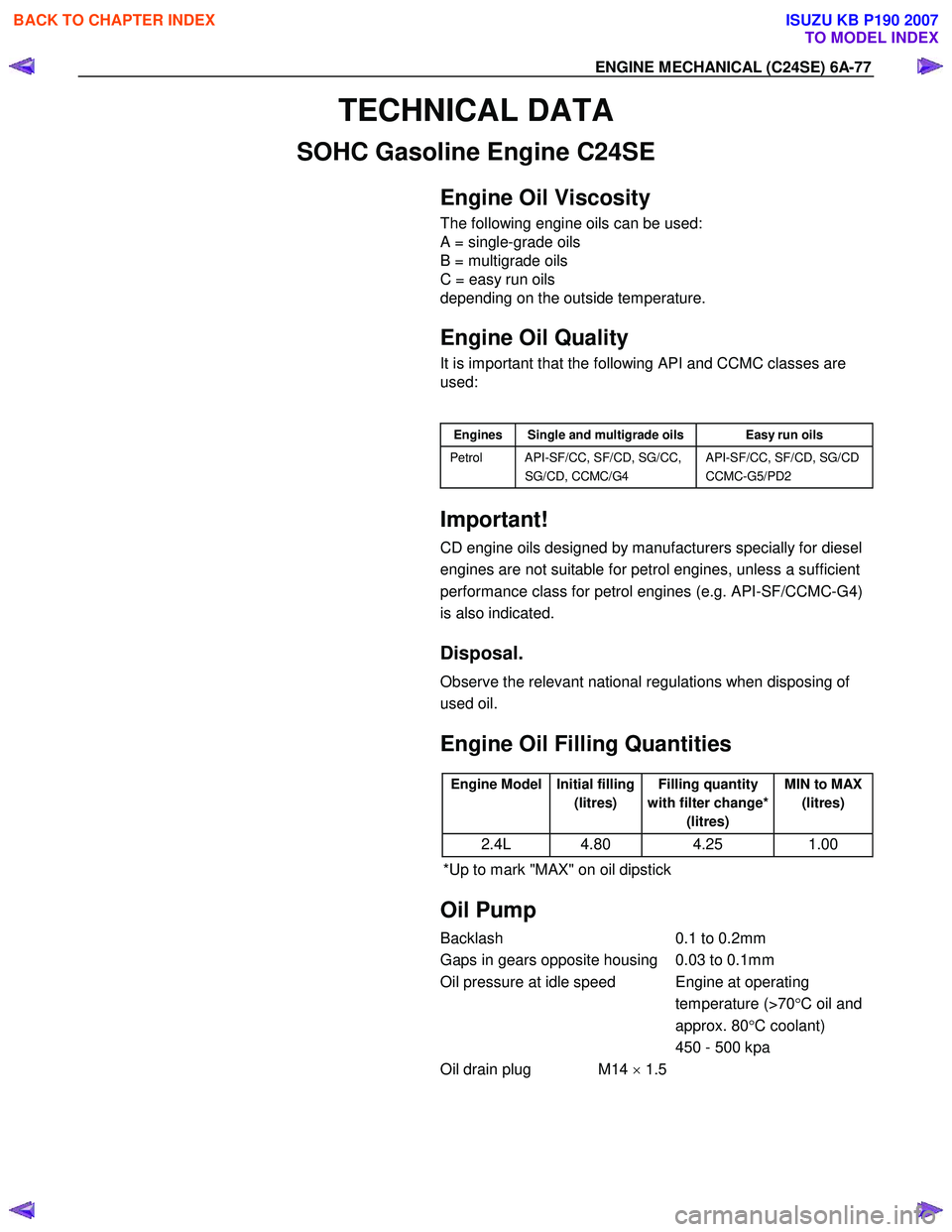
TECHNICAL DATA
SOHC Gasoline Engine C24SE
Engine Oil Viscosity
The following engine oils can be used:
A = single-grade oils
B = multigrade oils
C = easy run oils
depending on the outside temperature.
Engine Oil Quality
It is important that the following API and CCMC classes are
used:
Engines Single and multigrade oils Easy run oils
Petrol API-SF/CC, SF/CD, SG/CC,
SG/CD, CCMC/G4 API-SF/CC, SF/CD, SG/CD
CCMC-G5/PD2
Important!
CD engine oils designed by manufacturers specially for diesel
engines are not suitable for petrol engines, unless a sufficient
performance class for petrol engines (e.g. API-SF/CCMC-G4)
is also indicated.
Disposal.
Observe the relevant national regulations when disposing of
used oil.
Engine Oil Filling Quantities
Engine Model Initial filling
(litres) Filling quantity
with filter change* (litres) MIN to MAX
(litres)
2.4L 4.80 4.25 1.00
*Up to mark "MAX" on oil dipstick
Oil Pump
Backlash 0.1 to 0.2mm
Gaps in gears opposite housing 0.03 to 0.1mm
Oil pressure at idle speed Engine at operating temperature (>70°C oil and
approx. 80 °C coolant)
450 - 500 kpa
Oil drain plug M14 × 1.5
BACK TO CHAPTER INDEX
TO MODEL INDEX
ISUZU KB P190 2007
Page 2106 of 6020

6B-2 ENGINE COOLING
General Description
Legend
1 W ater Pump
2 Thermostat
3 Radiator
4 Reserve Tank 5 Coolant Distributor
6 Cylinder Block and Head
7 Throttle Body
8 Heater
The Cooling System is a pressurized type, where the water
pump, which is cambelt driven, forces the circulation of
the coolant through the cylinder block and head. The
thermostat regulates the flow of coolant between the
radiator and the bypass circuit. The heater is part of the
bypass circuit. The throttle body pre-heat is a separate
circuit which is not regulated by the thermostat. An oil
cooler may be fitted as part of this circuit.
BACK TO CHAPTER INDEX
TO MODEL INDEX
ISUZU KB P190 2007
Page 2108 of 6020

6B-4 ENGINE COOLING
Antifreeze Solution
• Calculating mixing ratio
Mixing ratio
= Antifreeze solution (Lit/gal.)
Antifreeze solution (Lit/gal.) + W ater (Lit/gal.)
NOTE: Antifreeze solution + W ater = Total cooling system
capacity.
• Total Cooling System Capacity
8Lit
• Mixing ratio
Check the specific gravity of engine coolant in the cooling system temperature ranges from 0 °C to 50 °C using a
suction type hydrometer, then determine the density of the
engine coolant by referring to the table.
NOTE: The LLC is 50% at all environment in order to prevent
the corrosion of cooling system parts.
BACK TO CHAPTER INDEX
TO MODEL INDEX
ISUZU KB P190 2007
Page 2109 of 6020

ENGINE COOLING 6B-5
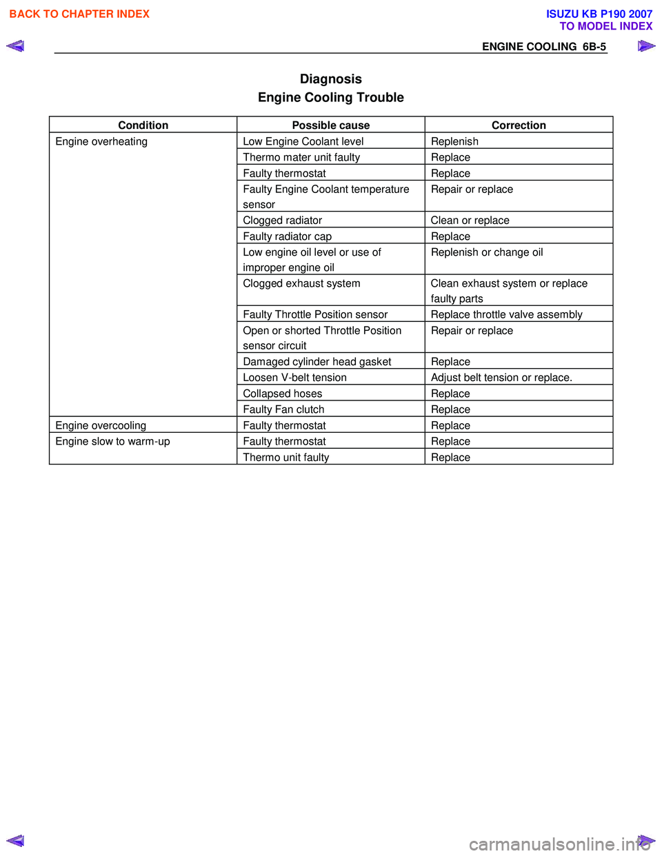
Diagnosis
Engine Cooling Trouble
Condition Possible cause Correction
Engine overheating Low Engine Coolant level Replenish
Thermo mater unit faulty Replace
Faulty thermostat Replace
Faulty Engine Coolant temperature
sensor Repair or replace
Clogged radiator Clean or replace
Faulty radiator cap Replace
Low engine oil level or use of
improper engine oil Replenish or change oil
Clogged exhaust system Clean exhaust system or replace
faulty parts
Faulty Throttle Position sensor Replace throttle valve assembly
Open or shorted Throttle Position
sensor circuit Repair or replace
Damaged cylinder head gasket Replace
Loosen V-belt tension Adjust belt tension or replace.
Collapsed hoses Replace
Faulty Fan clutch Replace
Engine overcooling Faulty thermostat Replace
Engine slow to warm-up Faulty thermostat Replace
Thermo unit faulty Replace
BACK TO CHAPTER INDEX
TO MODEL INDEX
ISUZU KB P190 2007
Page 2110 of 6020

6B-6 ENGINE COOLING
Draining and Refilling Cooling
System
Before draining the cooling system, inspect the system and
perform any necessary service to ensure that it is clean, does
not leak and is in proper working order. The engine coolant
level should be between the "MIN" and "MAX" lines of reserve
tank when the engine is cold. If low, check for leakage and add
engine coolant up to the "MAX" line. There should not be any
excessive deposit of rust or scales around the radiator cap or
radiator filler hole, and the engine coolant should also be free
from oil.
Replace the engine coolant if excessively dirty.
1. Completely drain the cooling system by opening the drain
plug at the bottom of the radiator.
2. Remove the radiator cap.
WARNING: TO AVOID THE DANGER OF BEING BURNED,
DO NOT REMOVE THE CAP WHILE THE ENGINE AND
RADIATOR ARE STILL HOT. SCALDING FLUID AND
STEAM CAN BE BLOWN OUT UNDER PRESSURE.
3. Disconnect all hoses from the engine coolant reserve tank.
Scrub and clean the inside of the reserve tank with soap and water. Flush it well with clean water, then drain it. Install
the reserve tank and hoses.
4. Refill the cooling system with the engine coolant using a solution that is at least 50 percent antifreeze.
5. Fill the radiator to the base of the filler neck.
Fill the engine coolant reserve tank to "MAX" line when the engine is cold.
6. Block the drive wheels and firmly apply the parking brake and place the shift lever in the "NEUTRAL" position.
7. Remove the radiator cap. Start the engine and warm it up at 2,500 - 3,000 rpm for about 30 minutes.
8. W hen the air comes out from the radiator filler neck and the engine coolant level has gone down, replenish with the
engine coolant. Repeat this procedure until the engine
coolant level does not go down. Then stop the engine and
install the radiator cap. Let the engine cool down.
9. After the engine has cooled, replenish with engine coolant up to the "MAX" line of the reserve tank.
10. Start the engine. W ith the engine running at 3,000 rpm, make sure there is no running water sound from the heate
r
core (behind the center console).
11. If the running water sound is heard, repeat steps 8 to 10.
BACK TO CHAPTER INDEX
TO MODEL INDEX
ISUZU KB P190 2007
Page 2111 of 6020

ENGINE COOLING 6B-7
Water Pump
Water Pump and Associated Parts
Legend
1 Water Pump Assembly 2 O-Ring
3 Bolt
2
3 1
Removal
1. Disconnect battery ground cable.
2. Drain coolant.
3. Disconnect radiator hose (on inlet pipe side).
4. Remove timing belt, refer to "Timing Belt" in this manual.
5. Remove water pump assembly.
Inspection
Make necessary repair and parts replacement if extreme wear
or damage is found during inspection. Should any of the
following problems occur, the entire water pump assembly
must be replaced:
BACK TO CHAPTER INDEX
TO MODEL INDEX
ISUZU KB P190 2007
Page 2113 of 6020

ENGINE COOLING 6B-9
Thermostat
Removal
1. Disconnect battery ground cable.
2. Drain engine coolant from the radiator and engine.
3. Disconnect radiator hose from the inlet pipe.
4. Remove thermostat housing.
5. Remove thermostat from thermostat housing.
Inspection
Suspend the thermostat in a water-filled container using thin
wire. Place a thermometer next to the thermostat.
Do not directly heat the thermostat.
Gradually increase the water temperature. Stir the water so
that the entire water is same temperature.
Confirm the temperature when the valve first begins to open.
Valve opening temperature 92 °
°°
°
C (197.6 °
°°
°
F)
Confirm the temperature when the valve is fully opened.
Valve full open temperature 107 °
°°
°
C(224.6 °
°°
°
F)
Make necessary repair and parts replacement if extreme wear
or damage is found during inspection.
Installation
1. Before installing thermostat, coat sealing surface with
silicon grease.
2. Install O-ring.
3. Install thermostat housing and tighten bolts to the specified torque.
Torque: 15 N ⋅
⋅⋅
⋅
m (1.5 kgf ⋅
⋅⋅
⋅
m)
4. Installation rubber hose.
5. Replenish engine coolant (EC).
6. Start engine and check for EC leakage.
Fan Clutch with Cooling Fan
Inspection and Repair
Make necessary correction or parts replacement if wear,
damage or any other abnormal condition are found through
inspection.
Visually inspect for damage, leak (silicon grease) or other
abnormal conditions.
1. Inspection (on-vehicle)
1) Turn the fan clutch by hand when in a low temperature condition before starting the engine, and confirm that it
can be turned readily.
2) Start the engine to warm it up until the temperature at the fan clutch portion gets to around 80 °C. Then stop the
engine and confirm that the fan clutch can be turned with
considerable effort (clutch torque) when turned by hand.
BACK TO CHAPTER INDEX
TO MODEL INDEX
ISUZU KB P190 2007
Page 2115 of 6020

ENGINE COOLING 6B-11
Radiator
Radiator and Associated Parts
Legend
1 Radiator Hose
2 Drain Plug
3 Fan Guide, Lower
4 Fan Guide
5 Bracket 6 Reserve Tank Hose
7 Reserve Tank
8 Radiator Cap
9 Radiator Assembly
Removal
1. Disconnect battery ground cable.
2. Loosen a drain plug to drain engine coolant (EC).
3. Disconnect radiator inlet hose and outlet hose.
4. Disconnect the reserve tank hose from radiator.
5. Lift out the radiator assembly, taking care not to damage the radiator core.
BACK TO CHAPTER INDEX
TO MODEL INDEX
ISUZU KB P190 2007
Page 2116 of 6020

6B-12 ENGINE COOLING
Inspection
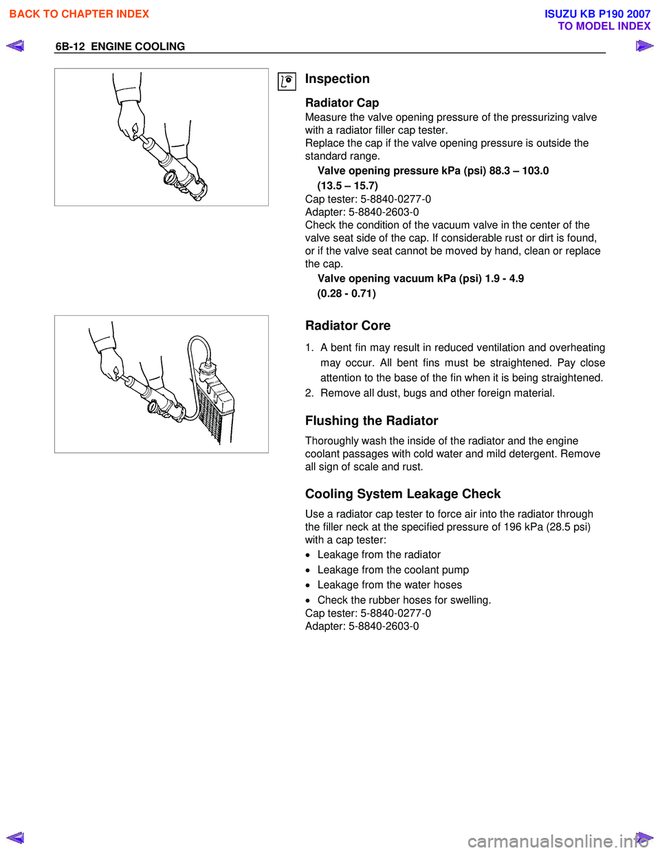
Radiator Cap
Measure the valve opening pressure of the pressurizing valve
with a radiator filler cap tester.
Replace the cap if the valve opening pressure is outside the
standard range.
Valve opening pressure kPa (psi) 88.3 – 103.0
(13.5 – 15.7)
Cap tester: 5-8840-0277-0
Adapter: 5-8840-2603-0
Check the condition of the vacuum valve in the center of the
valve seat side of the cap. If considerable rust or dirt is found,
or if the valve seat cannot be moved by hand, clean or replace
the cap.
Valve opening vacuum kPa (psi) 1.9 - 4.9
(0.28 - 0.71)
Radiator Core
1. A bent fin may result in reduced ventilation and overheating
may occur. All bent fins must be straightened. Pay close
attention to the base of the fin when it is being straightened.
2. Remove all dust, bugs and other foreign material.
Flushing the Radiator
Thoroughly wash the inside of the radiator and the engine
coolant passages with cold water and mild detergent. Remove
all sign of scale and rust.
Cooling System Leakage Check
Use a radiator cap tester to force air into the radiator through
the filler neck at the specified pressure of 196 kPa (28.5 psi)
with a cap tester:
• Leakage from the radiator
• Leakage from the coolant pump
• Leakage from the water hoses
• Check the rubber hoses for swelling.
Cap tester: 5-8840-0277-0
Adapter: 5-8840-2603-0
BACK TO CHAPTER INDEX
TO MODEL INDEX
ISUZU KB P190 2007