engine coolant ISUZU KB P190 2007 Workshop Repair Manual
[x] Cancel search | Manufacturer: ISUZU, Model Year: 2007, Model line: KB P190, Model: ISUZU KB P190 2007Pages: 6020, PDF Size: 70.23 MB
Page 1644 of 6020

ENGINE CONTROL SYSTEM (4JK1/4JJ1) 6E-27
Component Locator
Engine Controls Component Views
Legend1. Accelerator pedal position (APP) sensor
Legend
1. Barometric pressure (BARO) sensor (Standard output)
Legend 1. Crankshaft (CKP) sensor
Legend
1. Camshaft position (CMP) sensor
2. Engine coolant temperature (ECT) sensor
RTW56ESH004301
1
RTW76ESH002701
1
RTW76ESH002301
1
RTW56ESH002401
1 2
BACK TO CHAPTER INDEX
TO MODEL INDEX
ISUZU KB P190 2007
Page 1654 of 6020
ENGINE CONTROL SYSTEM (4JK1/4JJ1) 6E-37
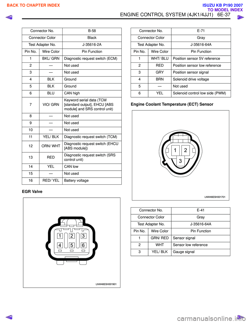
EGR ValveEngine Coolant Temperature (ECT) Sensor
Connector No.
B-58
Connector Color Black
Test Adapter No. J-35616-2A
Pin No. Wire Color Pin Function
1 BKL/ GRN Diagnostic request switch (ECM)
2 — Not used
3 — Not used
4 BLK Ground
5 BLK Ground
6 BLU CAN high
7 VIO/ GRN Keyword serial data (TCM
[standard output], EHCU [ABS
module] and SRS control unit)
8 — Not used
9 — Not used
10 — Not used 11 YEL/ BLK Diagnostic request switch (TCM)
12 ORN/ WHT Diagnostic request switch (EHCU
[ABS module])
13 RED Diagnostic request switch (SRS
control unit)
14 YEL CAN low
15 — Not used
16 RED/ YEL Battery voltage
LNW46ESH001901
1
4 2
5 3
6
Connector No. E-71
Connector Color Gray
Test Adapter No. J-35616-64A
Pin No. Wire Color Pin Function
1 WHT/ BLU Position sensor 5V reference
2 RED Position sensor low reference
3 GRY Position sensor signal
4 BRN Solenoid drive voltage
5—Not used
6 YEL Solenoid control low side (PWM)
Connector No. E-41
Connector Color Gray
Test Adapter No. J-35616-64A
Pin No. Wire Color Pin Function
1 GRN/ RED Sensor signal
2 WHT Sensor low reference
3 YEL/ BLK Gauge signal
LNW46ESH001701
12
3
BACK TO CHAPTER INDEX
TO MODEL INDEX
ISUZU KB P190 2007
Page 1664 of 6020

ENGINE CONTROL SYSTEM (4JK1/4JJ1) 6E-47
Scan Tool Data List
The Engine Scan Tool Data List contains all engine
related parameters that are available on the scan tool.
A given parameter may appear in any one of the data
lists, and in some cases may appear more than once,
or in more than one data list in order to group certain
related parameters together. Use the Engine Scan Tool
Data List only after the following is determined:
• The Engine Controls - Diagnostic System Check is completed. • On-board diagnostics are functioning properly.
Scan tool values from a properly running engine may
be used for comparison with the engine you are
diagnosing. The Engine Scan Tool Data List represents
values that would be seen on a normal running engine.
Only the parameters listed below are referenced in this
service manual for use in diagnosis.
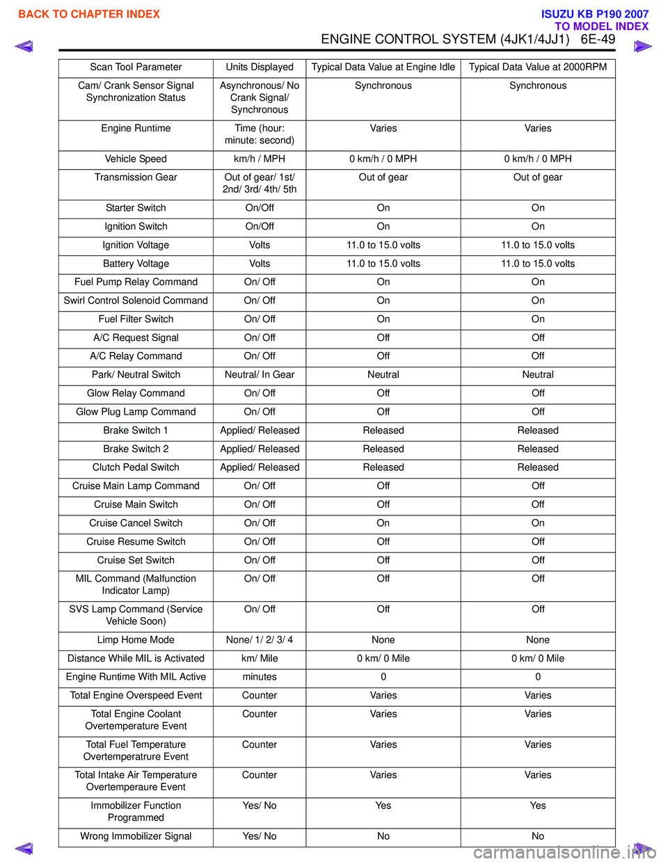
Scan Tool Parameter Units Displayed Typical Data Value at Engine Idle Typical Data Value at 2000RPM
Operating Conditions: Engine idling or 2000RPM/ Engine coolant temperature is between 75 to 85 °C (167 to 185 °F)/
Accelerator pedal is constant/ Neutral or Park/ Accessories OFF/ Vehicle located at sea level
Engine Speed RPMNearly 700 RPM Nearly 2000 RPM
Desired Engine Idle Speed RPM700 RPM 700 RPM
Calculated Engine Load %- -
Coolant Temperature °C/ °F 75 to 85 °C/ 167 to 185 °F 75 to 85 °C/ 167 to 185 °F
Engine Coolant Temperature Sensor Volts
0.4 to 0.6 volts 0.4 to 0.6 volts
Intake Air Temperature °C/ °F 20 to 40 °C/ 68 to 104 °F 20 to 40 °C/ 68 to 104 °F
Intake Air Temperature Sensor Volts 1.4 to 2.3 volts1.4 to 2.3 volts
Fuel Temperature °C/ °F 20 to 60 °C/ 68 to 140 °F 20 to 60 °C/ 68 to 140 °F
Fuel Temperature Sensor Volts0.8 to 2.3 volts 0.8 to 2.3 volts
MAF (Mass Air Flow) g/sec300 to 600 g/sec 200 to 600 g/sec
MAF Sensor (Mass Air Flow) Volts1.2 to 1.6 volts 2.0 to 2.7 volts
Barometric Pressure kPa/psi Nearly 100 kPa/ 14.5 psi at sea
levelNearly 100 kPa/ 14.5 psi at sea
level
Barometric Pressure Sensor VoltsNearly 2.3 volts at sea level Nearly 2.3 volts at sea level
Turbocharger Solenoid Command %
50 to 60 % 50 to 60 %
Desired Boost Pressure kPa/ psi Nearly 100 kPa/ 14.5 psi at sea
levelLess than 120 kPa/ 17.4 psi
Boost Pressure kPa/ psi Nearly 100 kPa/ 14.5 psi at sea
levelLess than 120 kPa/ 17.4 psi
Boost Pressure Sensor VoltsNearly 1.0 volt Less than 1.3 volts
Desired Fuel Rail Pressure MPa/ psi 30 MPa/ 4,350 psiMore than 70 MPa/ 10,200 psi
(4JJ1 Euro 4 specification)
More than 50 MPa/ 7,250 psi
(4JJ1 except Euro 4 specification)
More than 60 MPa/ 8,700 psi
(4JK1)
Fuel Rail Pressure MPa/ psi 27 to 33 MPa/ 3,900 to 4,800 psi More than 70 MPa/ 10,200 psi
(4JJ1 Euro 4 specification)
More than 50 MPa/ 7,250 psi (4JJ1 except Euro 4 specification)
More than 60 MPa/ 8,700 psi (4JK1)
BACK TO CHAPTER INDEX
TO MODEL INDEX
ISUZU KB P190 2007
Page 1666 of 6020
ENGINE CONTROL SYSTEM (4JK1/4JJ1) 6E-49
Cam/ Crank Sensor Signal Synchronization Status Asynchronous/ No
Crank Signal/ Synchronous Synchronous Synchronous
Engine Runtime Time (hour: minute: second) Va r i e s
Va r i e s
Vehicle Speed km/h / MPH0 km/h / 0 MPH 0 km/h / 0 MPH
Transmission Gear Out of gear/ 1st/ 2nd/ 3rd/ 4th/ 5th Out of gear
Out of gear
Starter Switch On/OffOn On
Ignition Switch On/OffOn On
Ignition Voltage Volts11.0 to 15.0 volts 11.0 to 15.0 volts
Battery Voltage Volts11.0 to 15.0 volts 11.0 to 15.0 volts
Fuel Pump Relay Command On/ Off OnOn
Swirl Control Solenoid Command On/ Off OnOn
Fuel Filter Switch On/ OffOn On
A/C Request Signal On/ OffOff Off
A/C Relay Command On/ OffOff Off
Park/ Neutral Switch Neutral/ In Gear NeutralNeutral
Glow Relay Command On/ OffOff Off
Glow Plug Lamp Command On/ Off OffOff
Brake Switch 1 Applied/ Released Released Released
Brake Switch 2 Applied/ Released Released Released
Clutch Pedal Switch Applied/ Released ReleasedReleased
Cruise Main Lamp Command On/ Off OffOff
Cruise Main Switch On/ OffOff Off
Cruise Cancel Switch On/ OffOn On
Cruise Resume Switch On/ OffOff Off
Cruise Set Switch On/ OffOff Off
MIL Command (Malfunction Indicator Lamp) On/ Off
Off Off
SVS Lamp Command (Service Vehicle Soon) On/ Off
Off Off
Limp Home Mode None/ 1/ 2/ 3/ 4 None None
Distance While MIL is Activated km/ Mile 0 km/ 0 Mile0 km/ 0 Mile
Engine Runtime With MIL Active minutes 00
Total Engine Overspeed Event Counter VariesVaries
Total Engine Coolant
Overtemperature Event Counter
Varies Varies
Total Fuel Temperature
Overtemperatrure Event Counter
Varies Varies
Total Intake Air Temperature Overtemperaure Event Counter
Varies Varies
Immobilizer Function Programmed Ye s / N o
Ye s Ye s
Wrong Immobilizer Signal Yes/ NoNo No
Scan Tool Parameter Units Displayed Typical Data Value at Engine Idle Typical Data Value at 2000RPM
BACK TO CHAPTER INDEX
TO MODEL INDEX
ISUZU KB P190 2007
Page 1667 of 6020

6E-50 ENGINE CONTROL SYSTEM (4JK1/4JJ1)
Scan Tool Data Definitions
This information will assist in emission or driveability
problems. The displays can be viewed while the vehicle
is being driven. Always perform the Diagnostic System
Check - Engine Controls first. The Diagnostic System
Check will confirm proper system operation.
Engine Speed
This parameter displays the rotational speed of the
crankshaft as calculated by the ECM based on inputs
from the crankshaft position (CKP) sensor or camshaft
position (CMP) sensor.
Desired Idle Speed
This parameter displays the idle speed requested by
the ECM. The ECM will change desired idle speed
based on engine coolant temperature and other inputs.
Calculate Engine Load
This parameter displays the engine load in percent
based on inputs to the ECM from various engine
sensors. The scan tool will display a lower percentage
when the engine is at idle with little or no load. The
scan tool will display a higher percentage when the
engine is running at high engine speed under a heavy
load.
Coolant Temperature
This parameter displays the temperature of the engine
coolant as calculated by the ECM using the signal from
the engine coolant temperature (ECT) sensor. The
scan tool will display a low temperature when the ECT
sensor signal voltage is high, and a high temperature
when the ECT sensor signal voltage is low.
Engine Coolant Temperature Sensor
This parameter displays the voltage signal sent to the
ECM from the engine coolant temperature (ECT)
sensor. ECT sensor is a range of value indicating a low
voltage when the temperature is high, and a high
voltage when the temperature is low.
Intake Air Temperature
This parameter displays the temperature of the intake
air as calculated by the ECM using the signal from the
intake air temperature (IAT) sensor. The scan tool will
display a low temperature when the IAT sensor signal
voltage is high, and a high temperature when the IAT
sensor signal voltage is low. Intake Air Temperature Sensor
This parameter displays the voltage signal sent to the
ECM from the intake air temperature (IAT) sensor. IAT
sensor is a range of value indicating a low voltage
when the temperature is high, and a high voltage when
the temperature is low.
Fuel Temperature
This parameter displays the temperature of the fuel as
calculated by the ECM using the signal from the fuel
temperature (FT) sensor. The scan tool will display a
low temperature when the FT sensor signal voltage is
high, and a high temperature when the FT sensor
signal voltage is low.
Fuel Temperature Sensor
This parameter displays the voltage signal sent to the
ECM from the fuel temperature (FT) sensor. FT sensor
is a range of value indicating a low voltage when the
temperature is high, and a high voltage when the
temperature is low.
MAF (Mass Air Flow)
This parameter displays the air flow into the engine as
calculated by the ECM based on the mass air flow
(MAF) sensor input. The scan tool will display a high
value at higher engine speeds, and a low value at lower
engine speed.
MAF Sensor (Mass Air Flow)
This parameter displays the voltage signal sent to the
ECM from the mass air flow (MAF) sensor. MAF sensor
is a range of value indicating a low voltage at lower
engine speed, and a high voltage at a higher engine
speeds.
Barometric Pressure
This parameter displays the barometric pressure
(BARO) as calculated by the ECM using the signal from
the BARO sensor. The scan tool will display a low
barometric pressure in high altitude area.
Barometric Pressure Sensor
This parameter displays the voltage signal sent to the
ECM from the barometric pressure (BARO) sensor.
BARO sensor is a range of value indicating a low
voltage in high altitude area, and a middle voltage in
sea level.
Immobilizer Signal Yes/ NoYes Yes
Security Wait Time Inactive/ Time
(hour: minute: second) Inactive
Inactive
Scan Tool Parameter Units Displayed Typical Data Value at Engine Idle Typical Data Value at 2000RPM
BACK TO CHAPTER INDEX
TO MODEL INDEX
ISUZU KB P190 2007
Page 1669 of 6020
6E-52 ENGINE CONTROL SYSTEM (4JK1/4JJ1)
Desired EGR Position
This parameter displays EGR position desired by the
ECM based on current driving conditions. This can be
compared to the actual EGR position to determine
sensor accuracy or EGR control problems.
EGR Position
This parameter displays the EGR valve position
calculated by the ECM using the signal from EGR
position sensor. The scan tool will display a low
percentage when the EGR valve is closed, and a high
percentage when the ERG valve is opened.
EGR Position Sensor
This parameter displays the voltage signal sent to the
ECM from the EGR position sensor. EGR position
sensor is a range of value indicating a low voltage
when the EGR valve is closed, and a high voltage when
the EGR valve is opened.
Intake Throttle Solenoid Command
This parameter displays the intake throttle solenoid
valve control duty ratio based on inputs to the ECM
from various engine sensors. The scan tool will display
a lower percentage when the intake throttle solenoid
valve is controlled to open. The scan tool will display a
higher percentage when the intake throttle solenoid
valve is controlled to close.
Desired Intake Throttle Position
This parameter displays intake throttle position desired
by the ECM based on current driving conditions. This
can be compared to the actual intake throttle position to
determine sensor accuracy or intake throttle control
problems.
Intake Throttle Position
This parameter displays the intake throttle valve
position calculated by the ECM using the signal from
intake throttle position sensor. The scan tool will display
a low percentage when the intake throttle valve is
closed, and a high percentage when the intake throttle
valve is opened. Note that the intake throttle position
indicates over 100% if the solenoid is commanded
OFF.
Intake Throttle Position Sensor
This parameter displays the voltage signal sent to the
ECM from the intake throttle position sensor. Intake
throttle position sensor is a range of value indicating a
low voltage when the intake throttle valve is closed to a
high voltage when the intake throttle valve is opened.
Desired Injection Quantity
This parameter displays a total injection quantity (main
injection quantity + pre injection quantity) desired by
the ECM based on current driving conditions.
Main Injection Quantity
This parameter displays a main injection quantity
desired by the ECM based on current driving
conditions. Main Injection Timing
This parameter displays a main injection timing desired
by the ECM based on current driving conditions.
Main Injection On Time
This parameter displays the time the ECM turns ON the
fuel injectors. The scan tool will display a higher value
with a longer pulse width, or a lower value with a
shorter pulse width.
Pre Injection Quantity
This parameter displays a pilot injection quantity
desired by the ECM based on current driving
conditions.
Pre Injection Interval
This parameter displays a injection interval between
end of pilot injection and start of main injection desired
by the ECM based on current driving condition.
Fuel Compensation Cyl. 1 to 4
This parameter displays the adjustment of fuel volume
for each cylinder at low engine speed area as
calculated by the ECM. The scan tool will display a
negative value if the fuel volume is lowered. The scan
tool will display a positive value if the fuel volume is
increased. If there is a cylinder that is excessively high
or low value, it may indicate faulty fuel injector, weak or
slightly seized cylinder or an incorrectly programmed
fuel injector ID code.
Cylinder Balancing Update
This parameter displays the state of the fuel
compensation for each cylinder. Enabled indicates the
adjustment of fuel volume for each cylinder is being
executed by the ECM when the engine is idle speed,
the engine coolant temperature sensor, the intake air
temperature sensor, barometric pressure sensor and
the vehicle speed sensor inputs are normal state.
Fuel Supply Pump Status
This parameter displays the learning state of the fuel
supply pump. Not Learn indicates initialized state that is
replaced to a new ECM or adjustment value is reset.
After engine is warm upped, leaning will start at idle
speed. Learning indicates learning state. Learned
indicates learning process is completed state.
Rail Pressure Feedback Mode
This parameter displays the state of the fuel rail
pressure feedback to the ECM. Wait Mode indicates
the ignition switch is turned ON position. Feedback
Mode indicates the engine is during crank or run.
Shutoff Mode indicates the ignition switch is turned
OFF position.
Engine Mode
This parameter displays the state of engine. Ignition On
indicates the ignition switch is turned ON position.
Cranking indicates the engine is during crank. Running
indicates the engine is run. Off indicates the ignition
switch is tuned OFF position.
BACK TO CHAPTER INDEX
TO MODEL INDEX
ISUZU KB P190 2007
Page 1671 of 6020
6E-54 ENGINE CONTROL SYSTEM (4JK1/4JJ1)
Cruise Cancel Switch
This parameter displays the input state of the cruise
cancel switch to the ECM. When the Cruise Cancel
switch is applied, the scan tool displays Off.
Cruise Resume Switch
This parameter displays the input state of the cruise
resume/accel. switch to the ECM. When the Cruise
Resume/Accel. switch is applied, the scan tool displays
On.
Cruise Set Switch
This parameter displays the input state of the cruise
set/coast switch to the ECM. When the Cruise Set/
Coast switch is pushed, the scan tool displays On.
MIL Command (Malfunction Indicator Lamp)
This parameter displays the commanded state of the
malfunction indicator lamp (MIL) control circuit. The
MIL should be On when the scan tool indicates
command On. The MIL should be Off when the scan
tool indicates command Off.
SVS Lamp Command (Service Vehicle Soon)
This parameter displays the commanded state of the
service vehicle soon (SVS) lamp control circuit. The
SVS lamp should be On when the scan tool indicates
command On. The SVS lamp should be Off when the
scan tool indicates command Off.
Limp Home Mode
This parameter indicates the state of the limp-home
mode. None indicates limp-home mode is not applied.
1, 2, 3 and 4 indicates fuel injection quantity reduction
is applied. 2 or higher number inhibits pilot injection. If 4
is indicated, engine running will be stopped when the
vehicle speed is less than 5 km/h (3 MPH) for 5
seconds.
Distance While MIL is Activated
This parameter displays the mileage since the
malfunction indicator lamp (MIL) is turned ON.
Engine Runtime With MIL Active
This parameter displays the engine run time elapsed
since the malfunction indicator lamp (MIL) is turned
ON. The scan tool will display the time in minutes.
Total Engine Overspeed Event
This parameter indicates counter of engine overspeed
event. Counter will be zero if any DTC is cleared.
Total Engine Coolant Overtemperature Event
This parameter indicates counter of engine overheat
event. The counter is active if engine coolant is over
11 0 °C (230 °F). Counter will be zero if any DTC is
cleared. Total Fuel Temperature Overtemperature Event
This parameter indicates counter of fuel temperature
excessively high condition. The counter is active if fuel
temperature is over 95 °C (203 °F). Counter will be zero
if any DTC is cleared.
Total Intake Air Temperature Overtemperature
Event
This parameter indicates counter of intake air
temperature excessively high condition. The counter is
active if intake air temperature is over 55 °C (131 °F).
Counter will be zero if any DTC is cleared.
Immobilizer Function Programmed
This parameter displays the state of the immobilizer
function programming in the ECM. The scan tool will
display Yes or No. Yes indicates the immobilizer
security information is correctly programmed in the
ECM. No indicates the ECM is not programmed or
ECM is reset.
Wrong Immobilizer Signal
This parameter displays the input state of the received
response signal to the ECM. When the ECM received
wrong response signal from the immobilizer control unit
(ICU), the scan tool displays Yes.
Immobilizer Signal
This parameter displays the input state of the response
signal to the ECM. When the ECM received any
response signal from the immobilizer control unit (ICU),
the scan tool displays Yes.
Security Wait Time
This parameter displays the security wait time length in
the ECM. Inactive indicates not in security wait time.
Time indicates under security wait time. This wait time
stage will prevent any further attempts to enter the
security code until the wait time has elapsed. The wait
time will increase each time an incorrect security code
is entered. Note that this parameter is not count
downed. It keeps displaying the same time until that
wait time has elapsed. The ignition switch must be kept
at ON position during the wait time period.
BACK TO CHAPTER INDEX
TO MODEL INDEX
ISUZU KB P190 2007
Page 1681 of 6020

6E-64 ENGINE CONTROL SYSTEM (4JK1/4JJ1)
61. Turn OFF the ignition.
2. Disconnect the FRP sensor harness connector.
3. Inspect for an intermittent, for poor connections and corrosion at the harness
connector of the FRP sensor (pins 1, 2 and 3
of E-48).
4. Disconnect the ECM harness connector.
5. Inspect for an intermittent, for poor connections and corrosion at the harness
connector of the ECM (pins 47, 48, 68 and 69
of E-90).
6. Test for high resistance on each circuit.
7. Repair the connection(s) or circuit(s) as necessary.
Did you find and correct the condition? —
Go to Step 11 Go to Step 7
7 Replace the FRP sensor. Refer to FRP Sensor
Replacement.
Did you complete the replacement? —
Go to Step 11
—
8Repair the short to ground between the ECM (pins
50 and 70 of E-90) and the FRP regulator (pin 2 of
E-50).
Did you compete the repair? —
Go to Step 11
—
91. Check for normal readings at key up for the
following sensor inputs: Use the Scan Tool
Data List or a known good vehicle to
determine nominal values.
• Engine Coolant Temperature Sensor
• Barometric Pressure (BARO) Sensor
• Boost Pressure Sensor
• Intake Throttle Position Sensor
2. Repair the circuit(s) or replace the sensor as necessary.
Did you find and correct the condition? —
Go to Step 11 Go to Step 10
10 1. Other possible causes for the no-start
condition:
• Engine mechanical timing
• Heavily restricted intake or exhaust plugged solid.
• Poor engine compression.
• Water or gasoline contamination in fuel.
2. Repair as necessary.
Did you find and correct the condition? —
Go to Step 11
—
111. Reconnect all previously disconnected
harness connector(s).
2. Turn OFF the ignition for 30 seconds.
3. Attempt to start the engine.
Does the engine start and continue to run? —
Go to Step 12 Go to Step 2
12 Observe the DTC Information with a scan tool.
Are there any DTCs that you have not diagnosed? —
Go to DTC List System OK
Step
Action Value(s)Yes No
BACK TO CHAPTER INDEX
TO MODEL INDEX
ISUZU KB P190 2007
Page 1712 of 6020

ENGINE CONTROL SYSTEM (4JK1/4JJ1) 6E-95
DTC P0101 (Flash Code 92)
Circuit Description
The mass air flow (MAF) sensor is an air flow meter
that measures the amount of air that enters the engine.
It is fitted between the air cleaner and turbocharger. A
small quantity of air that enters the engine indicates
deceleration or idle speed. A large quantity of air that
enters the engine indicates acceleration or a high load
condition. The ECM will calculate a predicted MAF
value and compares the actual MAF sensor voltage
signal to the predicted MAF value. This comparison will
determine if the signal is stuck, or is too low or too high
for a given operating condition. If the ECM detects that
the actual MAF sensor signal voltage is not within a
predetermined range of the calculated MAF value, this
DTC will set.
Condition for Running the DTC • DTCs P0045, P0102, P0103, P0107, P0108, P 0 11 2 , P 0 11 3 , P 0 11 6 , P 0 11 7 , P 0 11 8 , P 0 1 2 2 ,
P0123, P0234, P0403, P0404, P0405, P0406,
P0638, P0652, P0653, P0698, P0699, P1404,
P2100, P2101, P2103, P2227, P2228 and P2229
are not set.
AND following conditions are met longer than 10
seconds.
• The battery voltage is between 10.0 to 16.0 volts.
• The ignition switch is ON.
• The intake air temperature is less than 110 °C
(230 °F).
• The engine coolant temperature is between 0 to 11 0 °C (32 to 230 °F).
• The engine speed is between 850 to 3700 RPM.
• The EGR control is commanded OFF.
• The intake throttle control is commanded OFF.
• The commanded fuel injection quantity is OFF (accelerator pedal is not depressed).
• The engine run time is longer than 5 seconds. Condition for Setting the DTC
• The ECM detects that the MAF sensor signal voltage is not within a predetermined range of the
calculated MAF value for longer than 10 seconds.
Action Taken When the DTC Sets • The ECM illuminates the MIL when the diagnostic runs and fails. Refer to DTC Type Definitions for
Action Taken When the DTC Sets - Type A.
• The ECM limits fuel injection quantity.
• The ECM inhibits pilot injection.
• The ECM inhibits EGR control.
• The ECM inhibits cruise control.
Condition for Clearing the DTC • Refer to DTC Type Definitions for Condition for Clearing the MIL/ DTC - Type A.
Diagnostic Aids • Any unmetered air that enters the engine downstream of the MAF sensor will cause this
DTC to set.
• High resistance in the MAF sensor circuit will set this DTC.
• A short between the signal circuit of the MAF sensor and the signal circuit of the intake air
temperature (IAT) sensor will skew the MAF
sensor lower than normal at higher air flows.
Notice: • The MAF Sensor parameter on scan tool will only update with engine running or one time after the
key is cycled when the ignition has been turned
OFF for longer than 10 seconds.
Schematic Reference : Engine Controls Schematics
Connector End View Reference : Engine Controls
Connector End Views or ECM Connector End Views
Circuit/ System Testing DTC P0101
Step Action Value(s)Yes No
1 Did you perform the Diagnostic System Check -
Engine Controls? —
Go to Step 2 Go to Diagnostic
System Check -
Engine Controls
BACK TO CHAPTER INDEX
TO MODEL INDEX
ISUZU KB P190 2007
Page 1727 of 6020
6E-110 ENGINE CONTROL SYSTEM (4JK1/4JJ1)
DTC P0116 (Flash Code 23)
Circuit Description
The engine coolant temperature (ECT) sensor is
installed to the thermostat housing. The ECT sensor is
a variable resistor and it measures the temperature of
the engine coolant. If the ECM detects that the
difference of engine coolant temperature is smaller
than the calculated range during the predetermined
conditions, this DTC will set. This DTC will only run
once per ignition cycle within the enabling condition.
Condition for Running the DTC • DTCs P0117, P0118, P0201 - P0204, P0500, P0501 P124B, P1261, P1262 and P2146 - P2151
are not set.
• The ignition switch is ON.
• The engine coolant temperature is between -10 to 11 0 °C (14 to 230 °F).
• The vehicle run time is longer than 18 minutes.
• The engine run time is longer than 5 minutes with engine speed is more than 1200 RPM.
• The accumulation fuel injection quantity since engine start is more than a threshold.
Condition for Setting the DTC • The ECM detects that the difference of maximum and minimum engine coolant temperature is less
than 5 °C (9 °F). Action Taken When the DTC Sets
• The ECM illuminates the MIL when the diagnostic runs and fails. Refer to DTC Type Definitions for
Action Taken When the DTC Sets - Type A.
• The ECM limits fuel injection quantity.
• The ECM inhibits EGR control.
• The ECM inhibits cruise control.
Condition for Clearing the DTC • Refer to DTC Type Definitions for Condition for Clearing the MIL/ DTC - Type A.
Diagnostic Aids • After starting the engine the ECT should rise steadily to about 80 to 85 °C (176 to 185 °F) then
stabilize when the thermostat opens.
• Use the Temperature vs. Resistance table to test the ECT sensor at various temperature levels to
evaluate the possibility of a skewed sensor. A
skewed sensor could result in poor driveability
concerns.
Schematic Reference: Engine Controls Schematics
Connector End View Reference: Engine Controls
Connector End Views or ECM Connector End Views
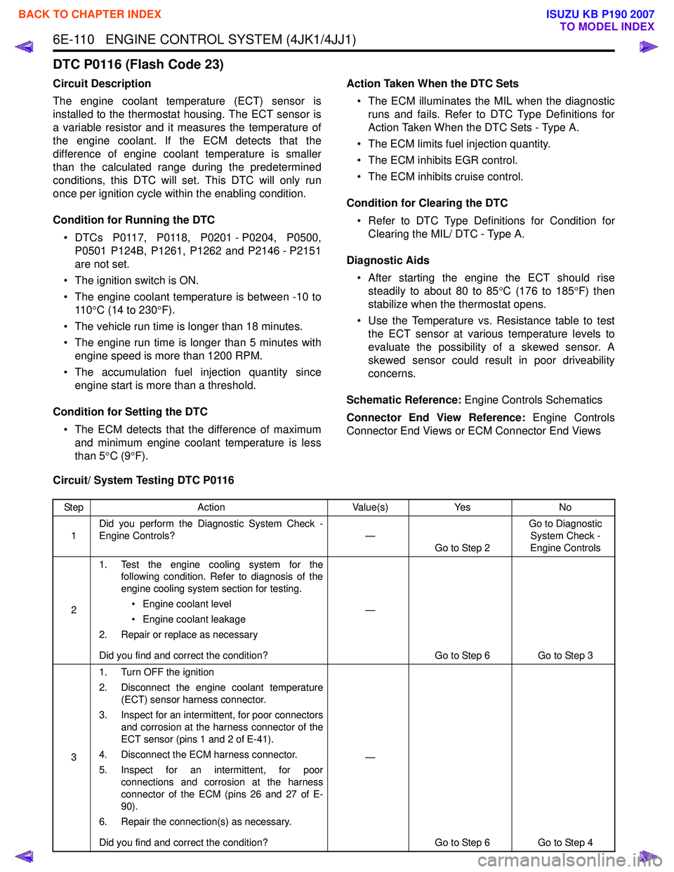
Circuit/ System Testing DTC P0116
Step Action Value(s)Yes No
1 Did you perform the Diagnostic System Check -
Engine Controls? —
Go to Step 2 Go to Diagnostic
System Check -
Engine Controls
2 1. Test the engine cooling system for the
following condition. Refer to diagnosis of the
engine cooling system section for testing.
• Engine coolant level
• Engine coolant leakage
2. Repair or replace as necessary
Did you find and correct the condition? —
Go to Step 6 Go to Step 3
3 1. Turn OFF the ignition
2. Disconnect the engine coolant temperature (ECT) sensor harness connector.
3. Inspect for an intermittent, for poor connectors and corrosion at the harness connector of the
ECT sensor (pins 1 and 2 of E-41).
4. Disconnect the ECM harness connector.
5. Inspect for an intermittent, for poor connections and corrosion at the harness
connector of the ECM (pins 26 and 27 of E-
90).
6. Repair the connection(s) as necessary.
Did you find and correct the condition? —
Go to Step 6 Go to Step 4
BACK TO CHAPTER INDEX
TO MODEL INDEX
ISUZU KB P190 2007