ECU ISUZU KB P190 2007 Workshop User Guide
[x] Cancel search | Manufacturer: ISUZU, Model Year: 2007, Model line: KB P190, Model: ISUZU KB P190 2007Pages: 6020, PDF Size: 70.23 MB
Page 516 of 6020
4C1-12 FRONT WHEEL DRIVE
17. Support the differential case by the jack.
18. Remove the front axle mounting bolts and nuts, lower the jack slowly. Remove the left side drive shaft end from the
knuckle, then lower the axle assembly from the vehicle.
CAUTION :
1. During the work, be sure that the axle assembly is supported securely.
2. Be careful not to damage the bellows of the power steering unit by interference.
3. Be careful not to damage the breather pipe and breather pip bracket of the shift on the fly by
interference.
Installation
1. Support the differential case by the jack.
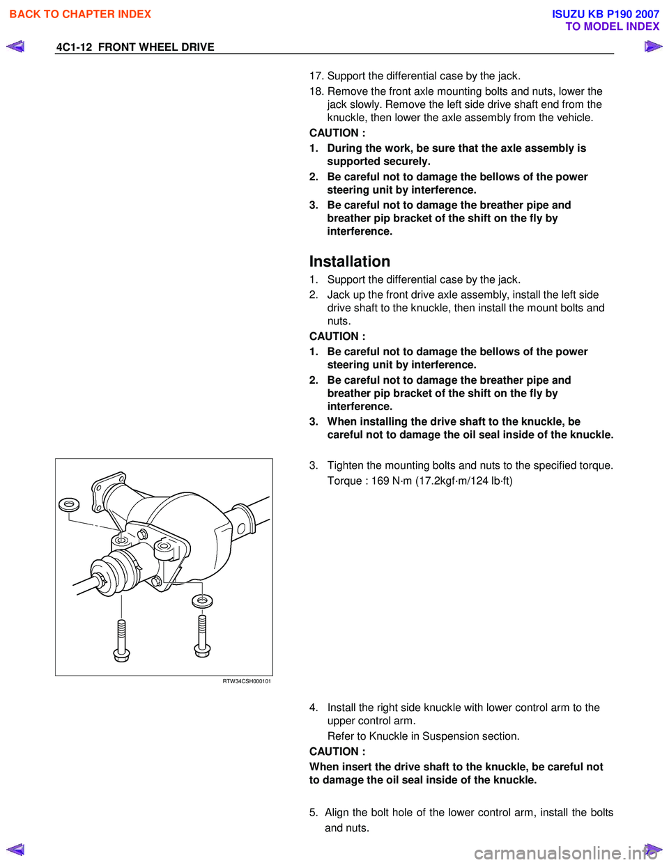
2. Jack up the front drive axle assembly, install the left side drive shaft to the knuckle, then install the mount bolts and
nuts.
CAUTION :
1. Be careful not to damage the bellows of the power steering unit by interference.
2. Be careful not to damage the breather pipe and breather pip bracket of the shift on the fly by
interference.
3. When installing the drive shaft to the knuckle, be careful not to damage the oil seal inside of the knuckle.
RTW 34CSH000101
3. Tighten the mounting bolts and nuts to the specified torque.
Torque : 169 N·m (17.2kgf·m/124 lb·ft)
4. Install the right side knuckle with lower control arm to the
upper control arm.
Refer to Knuckle in Suspension section.
CAUTION :
When insert the drive shaft to the knuckle, be careful not
to damage the oil seal inside of the knuckle.
5.
Align the bolt hole of the lower control arm, install the bolts
and nuts.
BACK TO CHAPTER INDEX
TO MODEL INDEX
ISUZU KB P190 2007
Page 522 of 6020

4C1-18 FRONT WHEEL DRIVE
Legend
1. UJ Case
2. Bellows
8. Install band. Note the setting direction. After installation,
check Standard Caulk Measure.
Discard the used band and install a new one.
Use the special tool pliers 5-8840-2745-0 to caulk the band to the specified value.
For both sides on UJ bellows.
Standard Caulk Measure
• 1.2mm (0.05in) <= (1), (2) <= 4.0mm (0.16in)
• (1) - (2) or (2) - (1) <= 0.4mm (0.016in)
9. Install another bellows and fix band.
Discard the used band and install a new one.
10. Install the ball guide with the smaller diameter side ahead onto the shaft.
11. Install ball retainer.
12. Using snap ring pliers, install the snap ring (1) securing the
ball retainer to the shaft.
Discard the used snap ring and install a new one.
BACK TO CHAPTER INDEX
TO MODEL INDEX
ISUZU KB P190 2007
Page 595 of 6020
BRAKE CON TROL SY STE M 5 A-2
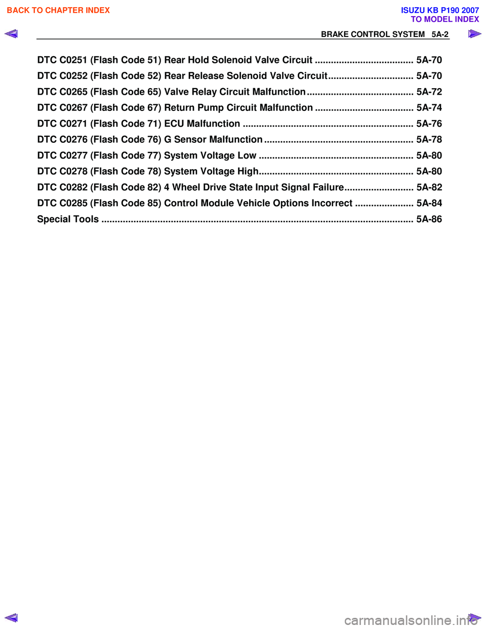
DTC C0251 (Flash Code 51) Rear Hold Solenoid Valve Circuit ..................................... 5A-70
DTC C0252 (Flash Code 52) Rear Release Solenoid Valve Circuit ................................ 5A-70
DTC C0265 (Flash Code 65) Valve Relay Circuit Malfunction ........................................ 5A-72
DTC C0267 (Flash Code 67) Return Pump Circuit Malfunction ..................................... 5A-74
DTC C0271 (Flash Code 71) ECU Malfunction ................................................................ 5A-76
DTC C0276 (Flash Code 76) G Sensor Malfunction ........................................................ 5A-78
DTC C0277 (Flash Code 77) System Voltage Low .......................................................... 5A-80
DTC C0278 (Flash Code 78) System Voltage High.......................................................... 5A-80
DTC C0282 (Flash Code 82) 4 Wheel Drive State Input Signal Failure.......................... 5A-82
DTC C0285 (Flash Code 85) Control Module Vehicle Options Incorrect ...................... 5A-84
Special Tools .................................................................................................................. ... 5A-86
BACK TO CHAPTER INDEX
TO MODEL INDEX
ISUZU KB P190 2007
Page 626 of 6020
BRAKE CONTROL SYSTEM 5A-33
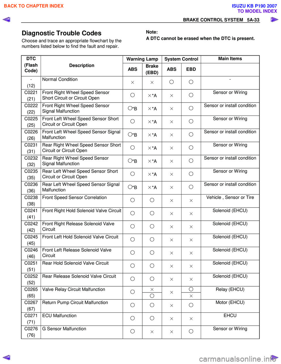
Diagnostic Trouble Codes
Choose and trace an appropriate flowchart by the
numbers listed below to find the fault and repair.
Note:
A DTC cannot be erased when the DTC is present.
Warning Lamp System Control Main Items
DTC
(Flash Code) Description
ABS Brake
(EBD) ABS EBD
-
(12) Normal Condition
× × -
C0221
(21) Front Right W heel Speed Sensor
Short Circuit or Circuit Open ×*A × Sensor or W iring
C0222
(22) Front Right W heel Speed Sensor
Signal Malfunction *B ×*A × Sensor or install condition
C0225
(25) Front Left W heel Speed Sensor Short
Circuit or Circuit Open ×*A × Sensor or W iring
C0226
(26) Front Left W heel Speed Sensor Signal
Malfunction *B ×*A × Sensor or install condition
C0231
(31) Rear Right W heel Speed Sensor Short
Circuit or Circuit Open ×*A × Sensor or W iring
C0232
(32) Rear Right W heel Speed Sensor
Signal Malfunction *B ×*A × Sensor or install condition
C0235
(35) Rear Left W heel Speed Sensor Short
Circuit or Circuit Open ×*A × Sensor or W iring
C0236
(36) Rear Left W heel Speed Sensor Signal
Malfunction *B ×*A × Sensor or install condition
C0238
(38) Front Speed Sensor Correlation
× × Vehicle , Sensor or Tire
C0241
(41) Front Right Hold Solenoid Valve Circuit
× × Solenoid (EHCU)
C0242
(42) Front Right Release Solenoid Valve
Circuit × × Solenoid (EHCU)
C0245
(45) Front Left Hold Solenoid Valve Circuit
× × Solenoid (EHCU)
C0246
(46) Front Left Release Solenoid Valve
Circuit × × Solenoid (EHCU)
C0251
(51) Rear Hold Solenoid Valve Circuit
× × Solenoid (EHCU)
C0252
(52) Rear Release Solenoid Valve Circuit
× × Solenoid (EHCU)
×
C0265
(65) Valve Relay Circuit Malfunction
×
× Relay (EHCU)
C0267
(67) Return Pump Circuit Malfunction
× Motor (EHCU)
C0271
(71) ECU Malfunction
× × EHCU
C0276
(76) G Sensor Malfunction
× × Sensor or W iring
BACK TO CHAPTER INDEX
TO MODEL INDEX
ISUZU KB P190 2007
Page 669 of 6020

5A-76 BRAKE CONTROL SYSTEM
DTC C0271 (Flash Code 71) ECU Malfunction
RTW 75ALF000301
Step Action Value(s) Yes No
1 W ere the steps of the “Basic Diagnostic Flow Chart”
performed?
- Go to Step 2 Go to Basic
Diagnostic
Flow Chart
2 1. Ignition “OFF”.
2. Check the EHCU circuit for an open, short to ground, or short to voltage. Also, check the EHCU
ignition feed circuit for an open or short to ground
and the EHCU ground circuit for an open or short to
voltage.
3. If a problem is found, repair as necessary. W as a problem found? - Verify repair Go to Step 3
BACK TO CHAPTER INDEX
TO MODEL INDEX
ISUZU KB P190 2007
Page 721 of 6020

5C-22 BRAKES
RTW 35CSH001001
•
••
•
Operation
1) Outline
W hen the LSPV (Load Sensing Proportioning Valve) detects a change in load weight, the load sensing spring
stretches.
Its reaction force is transmitted to the bottom of the load sensing valve to secure an optimum rear wheel cylinde
r
fluid pressure break point in proportion to the actual load
weight.
Besides, if the front brake system should fail, the device is designed to prevent the master cylinder fluid pressure from
decreasing and to apply it directly to the rear wheel cylinde
r
to obtain a sufficient braking performance.
RTW 35CSH001101
2) Bellow cutting point.
The Force (F) keeps the main piston (1) the rest position. The inlet pressure (A) and outlet pressure (B) are the same
as well as the inlet pressure (C) from front master cylinder.
The bypass piston (2) is kept on rest position by equilibrium
of the pressures (A) and (C) and the bypass spring load (3).
RTW 35CSH001201
3) Cutting point.
The cutting point is given by relation between force (F), that is the load applied by suspension of the vehicle and the
main piston area (1). The cutting point is achieved when the
force generated by hydraulic pressure is upper than the
force (F) given by the load suspension. The main piston (1)
moves from the rest position closing the valve. In this
moment the inlet pressure (A) is upper than the outlet
pressure (B). The bypass piston (2) continues on the rest
position by equilibrium of (A) and (C) pressure.
BACK TO CHAPTER INDEX
TO MODEL INDEX
ISUZU KB P190 2007
Page 723 of 6020
5C-24 BRAKES
RTW 35CSH000201
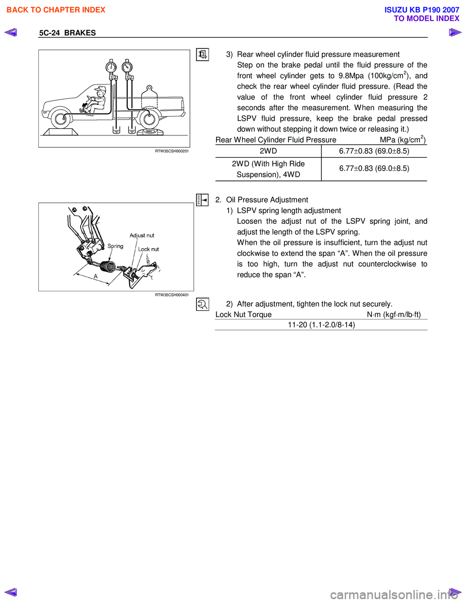
3) Rear wheel cylinder fluid pressure measurement
Step on the brake pedal until the fluid pressure of the front wheel cylinder gets to 9.8Mpa (100kg/cm
2), and
check the rear wheel cylinder fluid pressure. (Read the
value of the front wheel cylinder fluid pressure 2
seconds after the measurement. W hen measuring the
LSPV fluid pressure, keep the brake pedal pressed
down without stepping it down twice or releasing it.)
Rear W heel Cylinder Fluid Pressure MPa (kg/cm
2)
2W D 6.77 ±0.83 (69.0 ±8.5)
2W D (W ith High Ride
Suspension), 4W D 6.77
±0.83 (69.0 ±8.5)
RTW 35CSH000401
2. Oil Pressure Adjustment
1) LSPV spring length adjustment
Loosen the adjust nut of the LSPV spring joint, and adjust the length of the LSPV spring.
W hen the oil pressure is insufficient, turn the adjust nut clockwise to extend the span “A”. W hen the oil pressure
is too high, turn the adjust nut counterclockwise to
reduce the span “A”.
2) After adjustment, tighten the lock nut securely.
Lock Nut Torque N⋅m (kgf ⋅m/lb ⋅ft)
11-20 (1.1-2.0/8-14)
BACK TO CHAPTER INDEX
TO MODEL INDEX
ISUZU KB P190 2007
Page 734 of 6020
BRAKES 5C-35
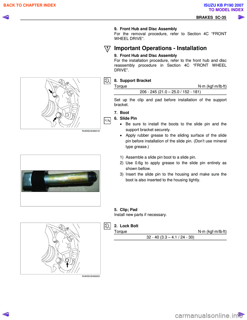
9. Front Hub and Disc Assembly
For the removal procedure, refer to Section 4C “FRONT
W HEEL DRIVE”.
Important Operations - Installation
9. Front Hub and Disc Assembly
For the installation procedure, refer to the front hub and disc
reassembly procedure in Section 4C “FRONT W HEEL
DRIVE”.
RUW 55CSH000101
8. Support Bracket
Torque N ⋅m (kgf ⋅m/lb ⋅ft)
206 - 245 (21.0 – 25.0 / 152 - 181)
Set up the clip and pad before installation of the support
bracket.
7. Boot
6. Slide Pin • Be sure to install the boots to the slide pin and the
support bracket securely.
•
Apply rubber grease to the sliding surface of the slide
pin before installation of the slide pin. (Don’t use mineral
type grease.)
1) Assemble a slide pin boot to a slide pin.
2) Use 0.6g to apply grease to the slide pin entirely as shown bellow.
3) Insert the slide pin to the housing and make sure the boot is also inserted to the housing tightly.
5. Clip; Pad
Install new parts if necessary.
RUW 55CSH000201
2. Lock Bolt
Torque N ⋅m (kgf ⋅m/lb ⋅ft)
32 - 40 (3.3 – 4.1 / 24 - 30)
BACK TO CHAPTER INDEX
TO MODEL INDEX
ISUZU KB P190 2007
Page 836 of 6020
ENGINE MECHANICAL 6A – 31
VALVE CLEARANCE ADJUSTMENT
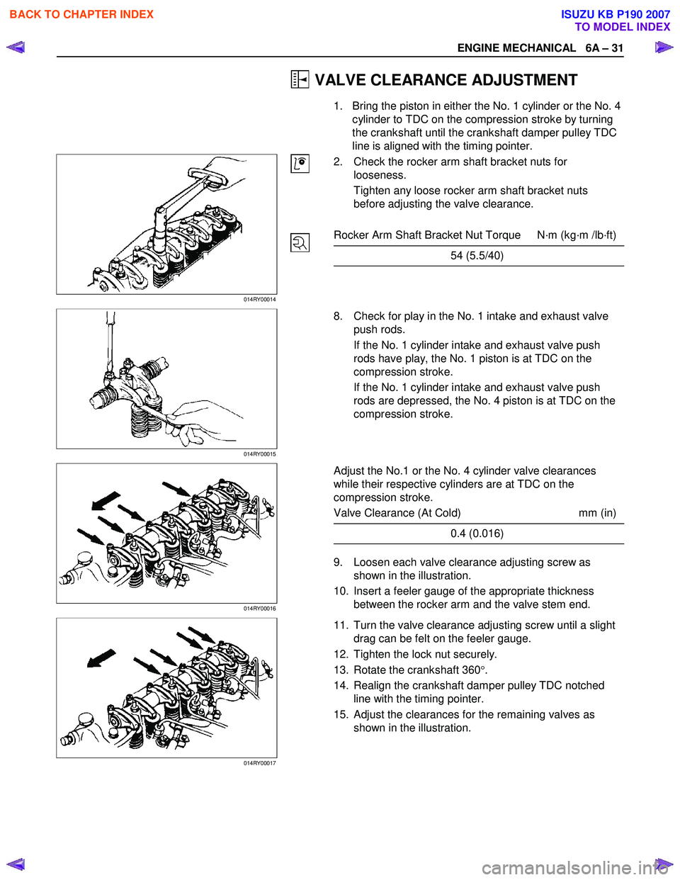
1. Bring the piston in either the No. 1 cylinder or the No. 4 cylinder to TDC on the compression stroke by turning
the crankshaft until the crankshaft damper pulley TDC
line is aligned with the timing pointer.
014RY00014
2. Check the rocker arm shaft bracket nuts for
looseness.
Tighten any loose rocker arm shaft bracket nuts
before adjusting the valve clearance.
Rocker Arm Shaft Bracket Nut Torque N·m (kg·m /lb·ft)
54 (5.5/40)
014RY00015
8. Check for play in the No. 1 intake and exhaust valve
push rods.
If the No. 1 cylinder intake and exhaust valve push
rods have play, the No. 1 piston is at TDC on the
compression stroke.
If the No. 1 cylinder intake and exhaust valve push
rods are depressed, the No. 4 piston is at TDC on the
compression stroke.
014RY00016
Adjust the No.1 or the No. 4 cylinder valve clearances
while their respective cylinders are at TDC on the
compression stroke.
Valve Clearance (At Cold) mm (in)
0.4 (0.016)
9. Loosen each valve clearance adjusting screw as
shown in the illustration.
10. Insert a feeler gauge of the appropriate thickness between the rocker arm and the valve stem end.
014RY00017
11. Turn the valve clearance adjusting screw until a slight
drag can be felt on the feeler gauge.
12. Tighten the lock nut securely.
13. Rotate the crankshaft 360 °.
14. Realign the crankshaft damper pulley TDC notched line with the timing pointer.
15. Adjust the clearances for the remaining valves as shown in the illustration.
BACK TO CHAPTER INDEX
TO MODEL INDEX
ISUZU KB P190 2007
Page 897 of 6020
6A – 92 E NGINE MECHANICAL
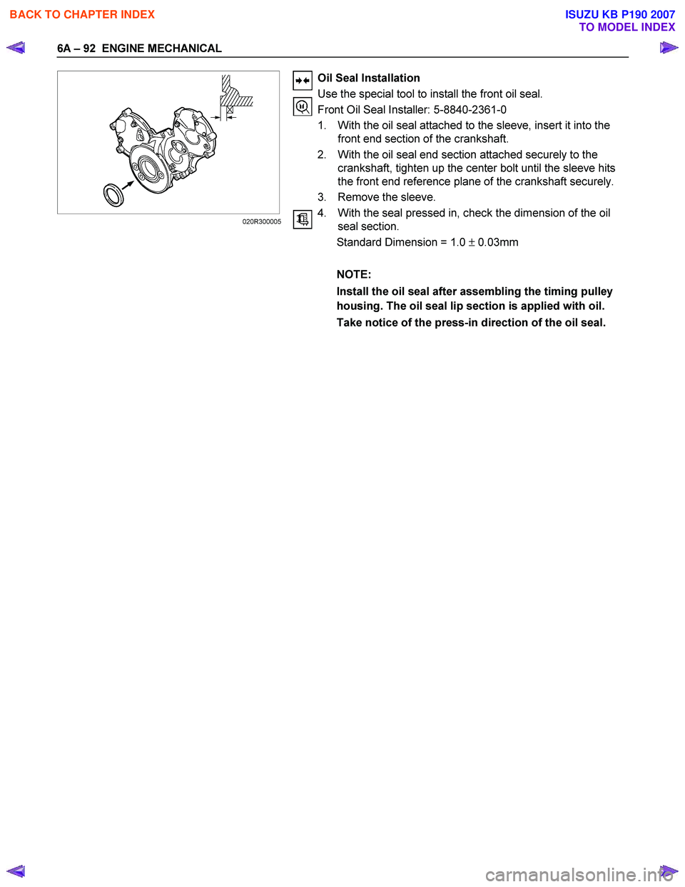
Oil Seal Installation
Use the special tool to install the front oil seal.
Front Oil Seal Installer: 5-8840-2361-0
1. With the oil seal attached to the sleeve, insert it into the front end section of the crankshaft.
2. With the oil seal end section attached securely to the crankshaft, tighten up the center bolt until the sleeve hits
the front end reference plane of the crankshaft securely.
3. Remove the sleeve.
4. With the seal pressed in, check the dimension of the oil seal section.
Standard Dimension = 1.0 ± 0.03mm
NOTE:
Install the oil seal after assembling the timing pulley
housing. The oil seal lip section is applied with oil.
Take notice of the press-in direction of the oil seal.
020R300005
BACK TO CHAPTER INDEX
TO MODEL INDEX
ISUZU KB P190 2007