fuel pressure ISUZU KB P190 2007 Workshop User Guide
[x] Cancel search | Manufacturer: ISUZU, Model Year: 2007, Model line: KB P190, Model: ISUZU KB P190 2007Pages: 6020, PDF Size: 70.23 MB
Page 923 of 6020
6A – 118 ENGINE MECHANICAL
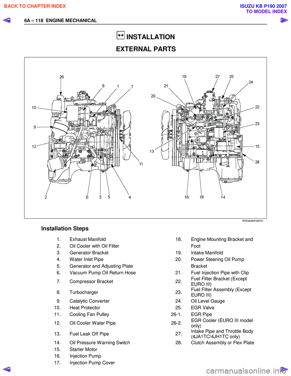
INSTALLATION
EXTERNAL PARTS
RTW 36AMF000701
Installation Steps
1.
Exhaust Manifold 18. Engine Mounting Bracket and
2.
Oil Cooler with Oil Filter Foot
3. Generator Bracket 19. Intake Manifold
4. W ater Inlet Pipe 20. Power Steering Oil Pump
5.
Generator and Adjusting Plate Bracket
6.
Vacuum Pump Oil Return Hose 21. Fuel Injection Pipe with Clip
7.
Compressor Bracket 22. Fuel Filter Bracket (Except
EURO III)
8. Turbocharger 23. Fuel Filter Assembly (Except
EURO III)
9. Catalytic Converter 24. Oil Level Gauge
10. Heat Protector 25. EGR Valve
11. Cooling Fan Pulley 26-1. EGR Pipe
12. Oil Cooler W ater Pipe 26-2. EGR Cooler (EURO III model
only)
13. Fuel Leak Off Pipe 27. Intake Pipe and Throttle Body
(4JA1TC/4JH1TC only)
14. Oil Pressure W arning Switch 28. Clutch Assembly or Flex Plate
15. Starter Motor
16. Injection Pump
17. Injection Pump Cover
BACK TO CHAPTER INDEX
TO MODEL INDEX
ISUZU KB P190 2007
Page 927 of 6020

6A – 122 ENGINE MECHANICAL
RTW 46ASH001601
9) Install the water feed adapter (1) with the gaskets to
turbocharger and tighten to the specified torque.
Adapter Torque N·m(kg·m/Ib ft)
39 (4.0/29)
10) Install the water feed pipe with the gaskets and tighten to the specified torque.
W ater Return Pipe Torque N·m(kg·m/Ib ft)
39 (4.0/29)
11) Install the water return pipe with the gaskets and tighten to the specified torque.
W ater Return Torque N·m(kg·m/Ib ft)
39 (4.0/29)
12) Clamp the water feed pipe to the oil return pipe of the turbocharger.
Fixing Bolt (3) Torque N·m(kg·m/Ib ft)
8 (0.8/6)
13) Install the hoses for the water feed and return.
9. Catalytic Converter
Install the catalytic converter with gasket and tighten the
nut to the specified torque.
Catalytic converter Nut Torque N·m(kg·m/Ib ft)
27 (2.7/20)
Do not install the catalytic converter, if drop down it.
10. Heat Protector Install the heat protector and tighten the bolt to the
specified torque.
Heat Protector Bolt Torque N·m(kg·m/Ib ft)
9 (0.9/6.5 Ib in)
033R300002
11. Cooling Fan Pulley
1) Install the cooling fan pulley to the water pump.
2) Tighten the cooling fan pulley nuts to the specified torque.
Pulley Nut Torque N·m(kg·m/Ib ft)
8 (0.8/6)
12. Oil Cooler Water Pipe
13. Fuel Leak Off Pipe
14. Oil Pressure Warning Switch
027R100007
BACK TO CHAPTER INDEX
TO MODEL INDEX
ISUZU KB P190 2007
Page 966 of 6020

6C – 2 FUEL SYSTEM
MAIN DATA AND SPECIFICATIONS
Description Item
4JA1T (L) 4JA1TC 4JH1TC
Injection pump type Bosch distributor
VE type Bosch distributor VP44 type
Governor type
Mechanical variable
(Half speed oil pressure) Electrical controled
Timer type
Oil pressure Electrical controled
Fuel feed pump type Vane with input shaft
Injection nozzle type Hole type
Number of injection nozzle orifices 5
Injection nozzle orifices
Inside diameter mm (in) 0.19 (0.0075) 0.17 (0.0067) 0.21 (0.0083)
19.1 (195) 19.0 (194) 19.5 (199) Injection nozzle designed operating
pressure MPa (kg/cm2) 1st
2nd 25.0 (255)
33.5 (328) 33.8 (331)
Main fuel filter type Disposable cartridge paper element
Precautions
When working on the fuel system, there are several things
to keep in mind:
•
Any time the fuel system is being worked on,
disconnect the negative battery cable except fo
r
those tests where battery voltage is required.
•
Always keep a dry chemical (Class B) fire
extinguisher near the work area.
• Replace all pipes with the same pipe and fittings that
were removed.
• Clean and inspect “O” rings. Replace if required.
•
Always relieve the line pressure before servicing any
fuel system components.
• Do not attempt repairs on the fuel system until you
have read the instructions and checked the pictures
relating to that repair.
• Adhere to all Notices and Cautions.
NOTE:
Injection nozzle adjustment is possible only on the 4JA1L
engine.
BACK TO CHAPTER INDEX
TO MODEL INDEX
ISUZU KB P190 2007
Page 970 of 6020
6C – 6 FUEL SYSTEM
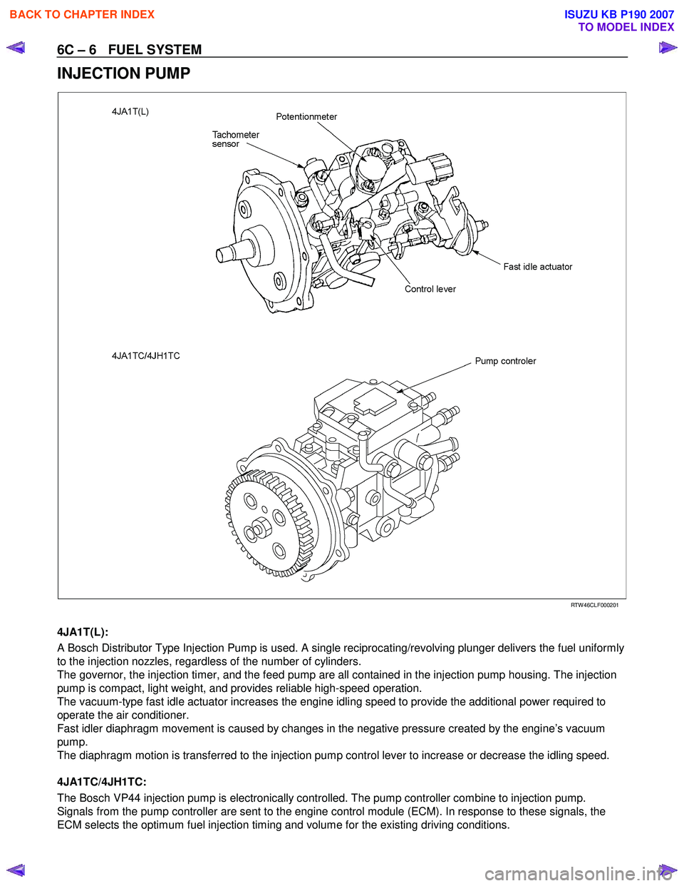
INJECTION PUMP
RTW 46CLF000201
4JA1T(L):
A Bosch Distributor Type Injection Pump is used. A single reciprocating/revolving plunger delivers the fuel uniformly
to the injection nozzles, regardless of the number of cylinders.
The governor, the injection timer, and the feed pump are all contained in the injection pump housing. The injection
pump is compact, light weight, and provides reliable high-speed operation.
The vacuum-type fast idle actuator increases the engine idling speed to provide the additional power required to
operate the air conditioner.
Fast idler diaphragm movement is caused by changes in the negative pressure created by the engine’s vacuum
pump.
The diaphragm motion is transferred to the injection pump control lever to increase or decrease the idling speed.
4JA1TC/4JH1TC:
The Bosch VP44 injection pump is electronically controlled. The pump controller combine to injection pump.
Signals from the pump controller are sent to the engine control module (ECM). In response to these signals, the
ECM selects the optimum fuel injection timing and volume for the existing driving conditions.
BACK TO CHAPTER INDEX
TO MODEL INDEX
ISUZU KB P190 2007
Page 973 of 6020
FUEL SYSTEM 6C – 9
Removal
CAUTION: When repair to the fuel system has been
completed, start engine and check the fuel system for
loose connection or leakage. For the fuel system
diagnosis, see Section “Driveability and Emission".
1. Disconnect battery ground cable.
2. Loosen slowly the fuel filler cap.
NOTE: Be careful not to spouting out fuel because of change
the pressure in the fuel tank.
NOTE: Cover opening of the filler neck to prevent any dust
entering.
3. Jack up the vehicle.
4. Support underneath of the fuel tank with a lifter.
5. Remove the inner liner of the wheel house at rear left side.
6. Remove fixing bolt of the filler neck from the body.
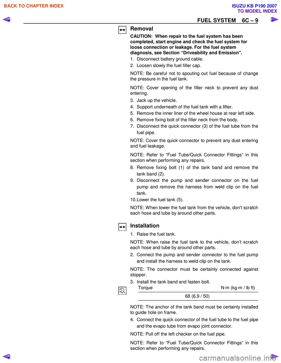
7. Disconnect the quick connector (3) of the fuel tube from the
fuel pipe.
NOTE: Cover the quick connector to prevent any dust entering
and fuel leakage.
NOTE: Refer to “Fuel Tube/Quick Connector Fittings” in this
section when performing any repairs.
8. Remove fixing bolt (1) of the tank band and remove the tank band (2).
9. Disconnect the pump and sender connector on the fuel
pump and remove the harness from weld clip on the fuel
tank.
10. Lower the fuel tank (5).
NOTE: W hen lower the fuel tank from the vehicle, don’t scratch
each hose and tube by around other parts.
Installation
1. Raise the fuel tank.
NOTE: W hen raise the fuel tank to the vehicle, don’t scratch
each hose and tube by around other parts.
2. Connect the pump and sender connector to the fuel pump and install the harness to weld clip on the tank.
NOTE: The connector must be certainly connected against
stopper.
3. Install the tank band and fasten bolt.
Torque N·m (kg·m / lb ft)
68 (6.9 / 50)
NOTE: The anchor of the tank band must be certainly installed
to guide hole on frame.
4. Connect the quick connector of the fuel tube to the fuel pipe and the evapo tube from evapo joint connector.
NOTE: Pull off the left checker on the fuel pipe.
NOTE: Refer to “Fuel Tube/Quick Connector Fittings” in this
section when performing any repairs.
BACK TO CHAPTER INDEX
TO MODEL INDEX
ISUZU KB P190 2007
Page 977 of 6020

FUEL SYSTEM 6C – 13
8. Check leak.
Methed of leak check.
(1) Plug end of quick connector and breather hose (Pull of
f
the breather hose from fuel tank) and tighten fuel filler
cap until at least one click are heard.
(2) Apply water soap around the fuel gauge unit seal area.
(3) Pressure air into the fuel tank from end of breather pipe
at 5psi (34.3 kPa/2.8kgf/cm
2) over 15 seconds.
(4) Verify no bubbles around the fuel gauge unit seal area.
9. Install the fuel tank assembly (9).
NOTE: Refer to “Install the fuel tank” in this section.
BACK TO CHAPTER INDEX
TO MODEL INDEX
ISUZU KB P190 2007
Page 978 of 6020
6C – 14 FUEL SYSTEM
FUEL TUBE / QUICK – CONNECTOR FITTINGS
Precautions
•
Do not light a match or create a flame.
• Keep flames away from your work area to prevent
flammable materials from catching fire.
• Disconnect battery ground cable to prevent electrical shorts.
• Pre-treat piping system or associated parts from thermal
damage or from spattering when welding or simila
r
heat-generating work.
140R100032
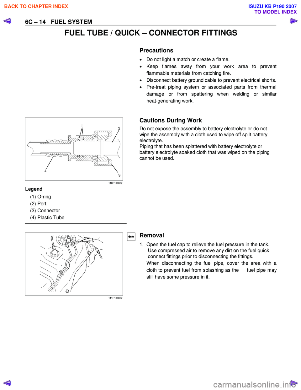
Legend
(1) O-ring
(2) Port
(3) Connector
(4) Plastic Tube
Cautions During Work
Do not expose the assembly to battery electrolyte or do not
wipe the assembly with a cloth used to wipe off spilt battery
electrolyte.
Piping that has been splattered with battery electrolyte or
battery electrolyte soaked cloth that was wiped on the piping
cannot be used.
141R100002
Removal
1. Open the fuel cap to relieve the fuel pressure in the tank.
Use compressed air to remove any dirt on the fuel quick
connect fittings prior to disconnecting the fittings.
W hen disconnecting the fuel pipe, cover the area with a
cloth to prevent fuel from splashing as the fuel pipe ma
y
still have some pressure in it.
BACK TO CHAPTER INDEX
TO MODEL INDEX
ISUZU KB P190 2007
Page 981 of 6020
FUEL SYSTEM 6C – 17
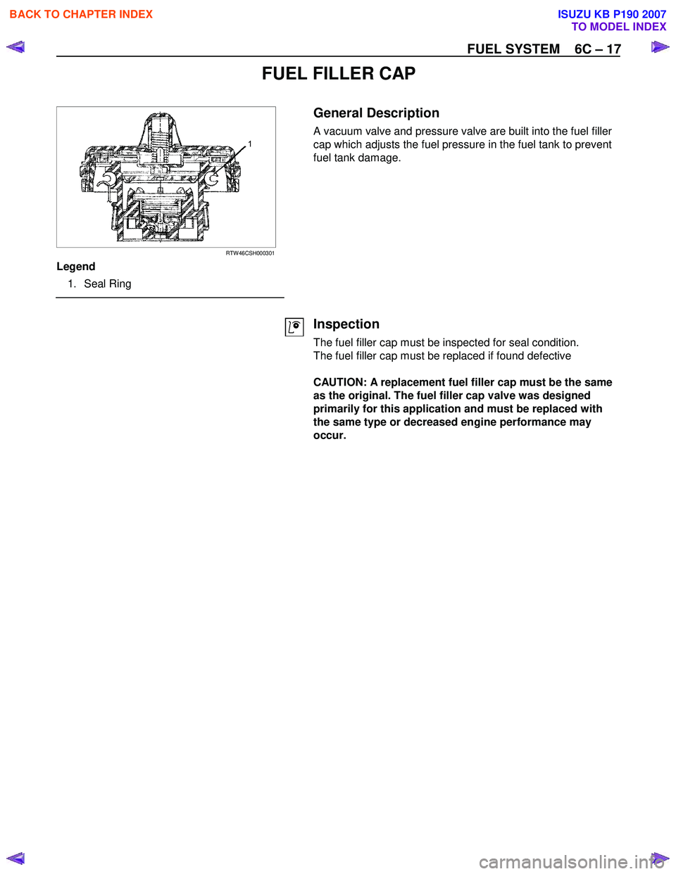
FUEL FILLER CAP
RTW 46CSH000301
Legend
1. Seal Ring
General Description
A vacuum valve and pressure valve are built into the fuel filler
cap which adjusts the fuel pressure in the fuel tank to prevent
fuel tank damage.
Inspection
The fuel filler cap must be inspected for seal condition.
The fuel filler cap must be replaced if found defective
CAUTION: A replacement fuel filler cap must be the same
as the original. The fuel filler cap valve was designed
primarily for this application and must be replaced with
the same type or decreased engine performance may
occur.
BACK TO CHAPTER INDEX
TO MODEL INDEX
ISUZU KB P190 2007
Page 989 of 6020
FUEL SYSTEM 6C – 25
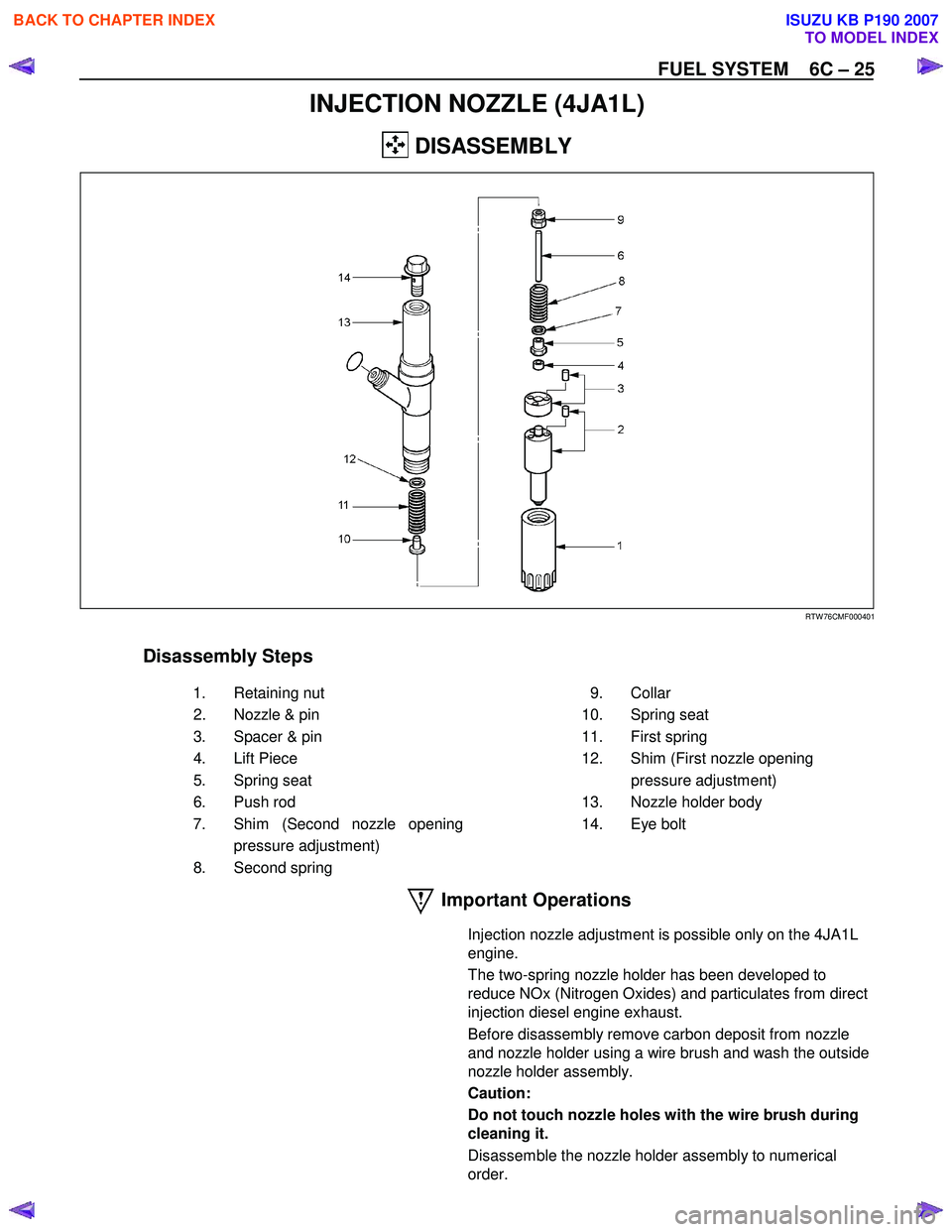
INJECTION NOZZLE (4JA1L)
DISASSEMBLY
RTW 76CMF000401
Disassembly Steps
1. Retaining nut 2. Nozzle & pin
3. Spacer & pin
4. Lift Piece
5. Spring seat
6. Push rod
7. Shim (Second nozzle opening pressure adjustment)
8. Second spring 9. Collar
10. Spring seat
11. First spring
12. Shim (First nozzle opening pressure adjustment)
13. Nozzle holder body
14. Eye bolt
Important Operations
Injection nozzle adjustment is possible only on the 4JA1L
engine.
The two-spring nozzle holder has been developed to
reduce NOx (Nitrogen Oxides) and particulates from direct
injection diesel engine exhaust.
Before disassembly remove carbon deposit from nozzle
and nozzle holder using a wire brush and wash the outside
nozzle holder assembly.
Caution:
Do not touch nozzle holes with the wire brush during
cleaning it.
Disassemble the nozzle holder assembly to numerical
order.
BACK TO CHAPTER INDEX
TO MODEL INDEX
ISUZU KB P190 2007
Page 990 of 6020
6C – 26 FUEL SYSTEM
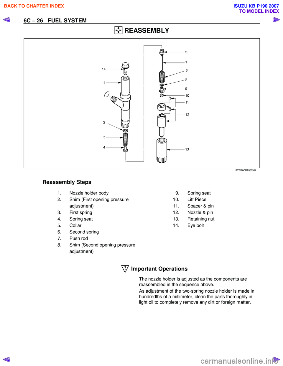
REASSEMBLY
RTW 76CMF000501
Reassembly Steps
1. Nozzle holder body 2. Shim (First opening pressure adjustment)
3. First spring
4. Spring seat
5. Collar
6. Second spring
7. Push rod
8. Shim (Second opening pressure adjustment) 9. Spring seat
10. Lift Piece
11. Spacer & pin
12. Nozzle & pin
13. Retaining nut
14. Eye bolt
Important Operations
The nozzle holder is adjusted as the components are
reassembled in the sequence above.
As adjustment of the two-spring nozzle holder is made in
hundredths of a millimeter, clean the parts thoroughly in
light oil to completely remove any dirt or foreign matter.
BACK TO CHAPTER INDEX
TO MODEL INDEX
ISUZU KB P190 2007