keyless ISUZU KB P190 2007 Workshop User Guide
[x] Cancel search | Manufacturer: ISUZU, Model Year: 2007, Model line: KB P190, Model: ISUZU KB P190 2007Pages: 6020, PDF Size: 70.23 MB
Page 5480 of 6020
8A-542 ELECTRICAL-BODY AND CHASSIS
KEYLESS ENTRY CONTROL UNIT
Removal
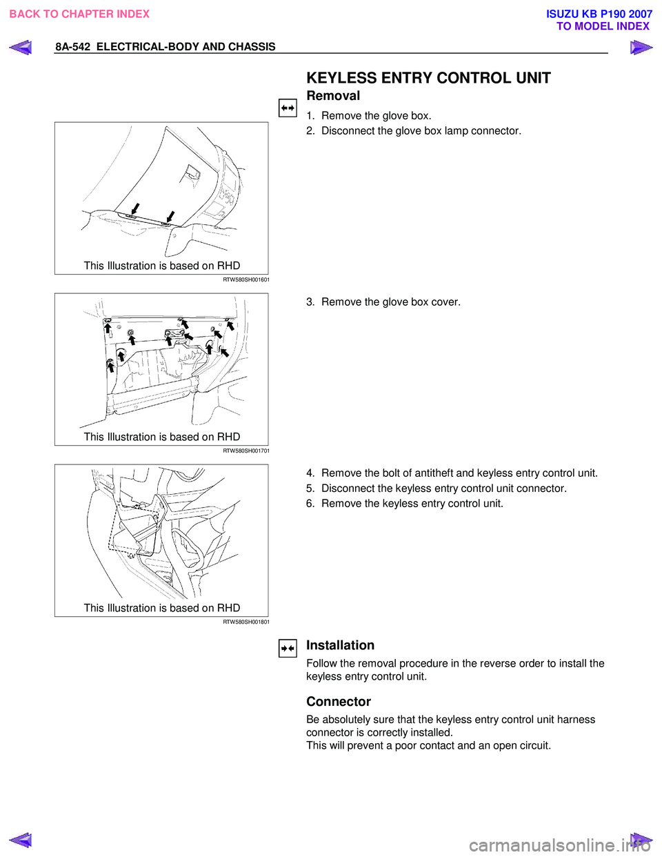
1. Remove the glove box.
This Illustration is based on RHD
RTW 580SH001601
2. Disconnect the glove box lamp connector.
This Illustration is based on RHD
RTW 580SH001701
3. Remove the glove box cover.
This Illustration is based on RHD
RTW 580SH001801
4. Remove the bolt of antitheft and keyless entry control unit.
5. Disconnect the keyless entry control unit connector.
6. Remove the keyless entry control unit.
Installation
Follow the removal procedure in the reverse order to install the
keyless entry control unit.
Connector
Be absolutely sure that the keyless entry control unit harness
connector is correctly installed.
This will prevent a poor contact and an open circuit.
BACK TO CHAPTER INDEX TO MODEL INDEXISUZU KB P190 2007
Page 5482 of 6020

8A-544 ELECTRICAL-BODY AND CHASSIS
Keyless Entry System
General Description
The system’s main features are summarized as follows.
・ Keyless entry with visual feedback
・ Highly secure encrypted transmission format
incorporating rolling code strategy
・ Field programmable remote keys
・ Door lock control
・ Illuminated entry with fade out
・ Illuminated exit
・ Remote door lock / ignition key interlock
・ Door ajar warning indicator in the cluster
BACK TO CHAPTER INDEX
TO MODEL INDEXISUZU KB P190 2007
Page 5484 of 6020
8A-546 ELECTRICAL-BODY AND CHASSIS
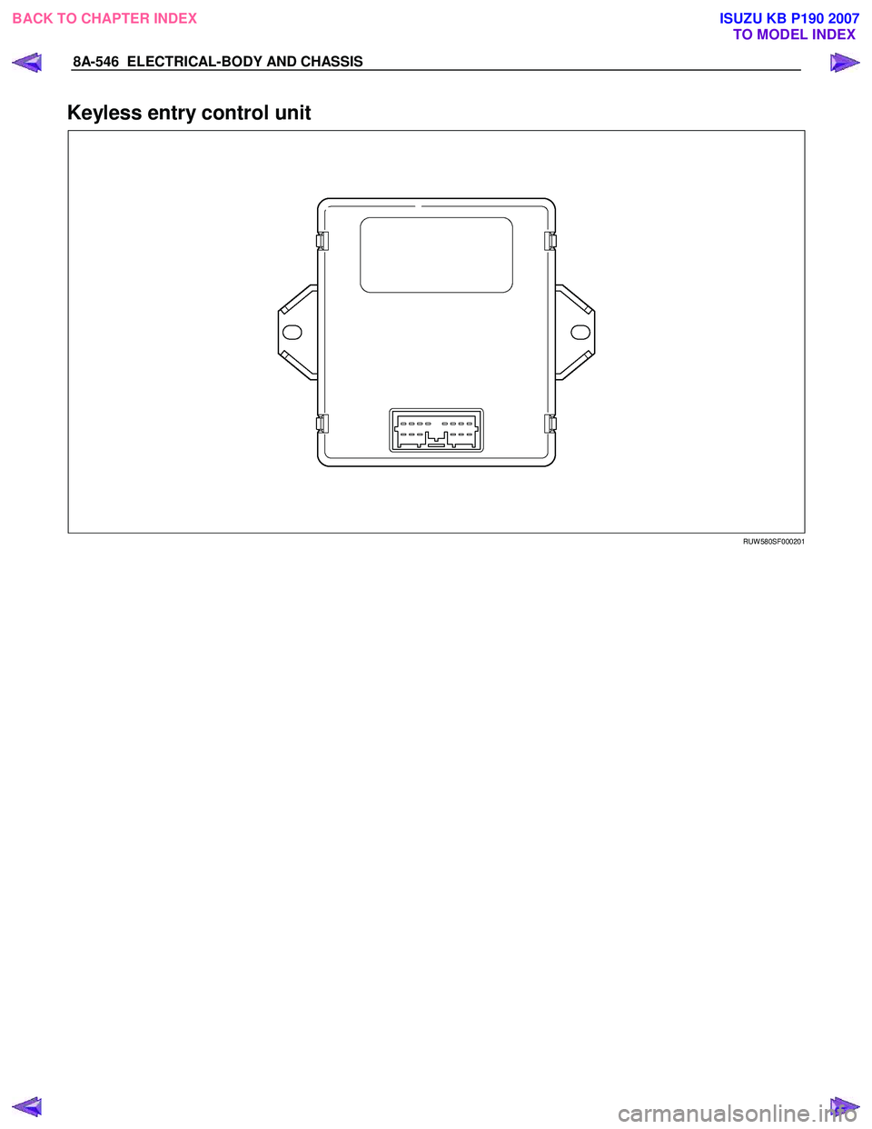
Keyless entry control unit
RUW 580SF000201
BACK TO CHAPTER INDEX TO MODEL INDEXISUZU KB P190 2007
Page 5516 of 6020

8A-578 ELECTRICAL-BODY AND CHASSIS
KEYLESS ENTRY CONTROL UNIT
Removal
1. Remove the glove box.
RTW 580SH001601
2. Disconnect the glove box lamp connector.
RTW 580SH001701
3. Remove the glove box cover.
RTW 580SH001801
4. Remove the bolt of antitheft and keyless entry control unit.
5. Disconnect the antitheft and keyless entry control unitconnector.
6. Remove the antitheft and keyless entry control unit.
Installation
Follow the removal procedure in the reverse order to install the
antitheft and keyless entry control unit.
Connector
Be absolutely sure that the antitheft and keyless entry control
unit harness connector is correctly installed.
This will prevent a poor contact and an open circuit.
BACK TO CHAPTER INDEX TO MODEL INDEXISUZU KB P190 2007
Page 5518 of 6020
8A-580 ELECTRICAL-BODY AND CHASSIS
TECH-2 OPERATION AND PROGRAMING
KEYLESS ENTRY
General Description
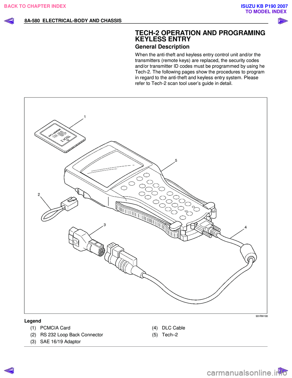
W hen the anti-theft and keyless entry control unit and/or the
transmitters (remote keys) are replaced, the security codes
and/or transmitter ID codes must be programmed by using he
Tech-2. The following pages show the procedures to program
in regard to the anti-theft and keyless entry system. Please
refer to Tech-2 scan tool user’s guide in detail.
901RW 180
Legend
(1) PCMCIA Card (4) DLC Cable
(2) RS 232 Loop Back Connector (5)Tech–2
(3) SAE 16/19 Adaptor
BACK TO CHAPTER INDEX TO MODEL INDEXISUZU KB P190 2007
Page 5522 of 6020

8A-584 ELECTRICAL-BODY AND CHASSIS
RTW 38DLH000101
Menu
The left table shows witch functions are used for the
available equipment versions.
NOTE: Marked items are not applied for keyless entry
system.
DTC
On OBD has three options available in the Tech-2
DTC mode to display the enhanced information
available.
• Read DTC Info Ordered By Priority.
• Read DTC Info As Stored By ECU.
• Clear DTC and Alarm Code Info.
Clear DTC Information
To clear Diagnostic Trouble Codes (DTCs), Use the
diagnostic scan tool “Clear DTC Information” function.
Tech-2 Data Display
The Tech-2 data values represent values that would
be seen on a normally-keyless entry system.
RTW 38DSH001601
Actuator Test
Unlock/Lock Test
Check whether opening and closing of a door lock
can be performed by operation of Tech-2.
1. Turn the key “OFF”.
2. Turn the key “ON”.
3. Check the display and test menu.
4. Operate the Tech-2.
BACK TO CHAPTER INDEX TO MODEL INDEXISUZU KB P190 2007
Page 5547 of 6020
ELECTRICAL-BODY AND CHASSIS 8A-609
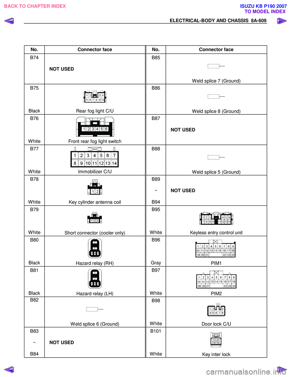
No. Connector face No. Connector face
B74
NOT USED B85
W eld splice 7 (Ground)
B75
Black
Rear fog light C/U B86
W eld splice 8 (Ground)
B76
White
Front rear fog light switch B87
NOT USED
B77
White
Immobilizer C/U B88
W eld splice 5 (Ground)
B78
White
Key cylinder antenna coil B89
~
B94 NOT USED
B79
White
Short connector (cooler only) B95
White
Keyless entry control unit
B80
Black
Hazard relay (RH) B96
Gray PIM1
B81
Black
Hazard relay (LH) B97
WhitePIM2
B82
W eld splice 6 (Ground) B98
WhiteDoor lock C/U
B83
~
B84 NOT USED B101
White
Key inter lock
BACK TO CHAPTER INDEX TO MODEL INDEXISUZU KB P190 2007
Page 5555 of 6020
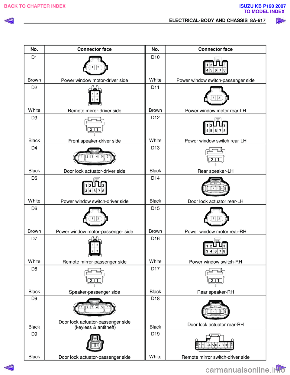
ELECTRICAL-BODY AND CHASSIS 8A-617
No. Connector face No. Connector face
D1
Brown
Power window motor-driver side D10
White
Power window switch-passenger side
D2
White
Remote mirror-driver side D11
BrownPower window motor rear-LH
D3
Black
Front speaker-driver side D12
White
Power window switch rear-LH
D4
Black
Door lock actuator-driver side D13
BlackRear speaker-LH
D5
White
Power window switch-driver side D14
BlackDoor lock actuator rear-LH
D6
Brown
Power window motor-passenger side D15
BrownPower window motor rear-RH
D7
White
Remote mirror-passenger side D16
WhitePower window switch-RH
D8
Black
Speaker-passenger side D17
BlackRear speaker-RH
D9
Black
Door lock actuator-passenger side (keyless & antitheft) D18
BlackDoor lock actuator rear-RH
D9
Black
Door lock actuator-passenger side D19
WhiteRemote mirror switch-driver side
BACK TO CHAPTER INDEX TO MODEL INDEXISUZU KB P190 2007
Page 5925 of 6020

IMMOBILIZER SYSTEM (C24SE, 4JA1-T) 11A-27
Diagnostic procedure
• Once the cause of DTC is repaired or gone,
engine can be operated normally, and present
DTC becomes history code.
• History code is canceled by no repeat failure on 25
consequence ignition key on afterward.
• History code cannot be canceled by batter
y
connector disconnected.
Clearing Diagnostic Trouble Codes
IMPORTANT: Do not clear DTCs unless directed to do
so by the service information provided for each
diagnostic procedure. W hen DTCs are cleared, the
Failure Record data which may help diagnose an
intermittent fault will also be erased from memory.
Verifying Vehicle Repair
Verification of vehicle repair will be more
comprehensive for vehicles with immobilizer system
diagnostic. Following a repair, the technician should
perform the following steps:
1. Review and record the Fail Records for the DTC
which has been diagnosed.
2. Clear DTC(s).
3. Operate the vehicle within conditions noted in the
Fail Records.
4. Monitor the DTC status information for the DTC
which has been diagnosed until the diagnostic test
associated with that DTC runs.
Following these steps are very important in verifying
repairs on immobilizer systems. Failure to follow these
steps could result in unnecessary repairs.
Diagnostic Aids
Check the condition for system parts.
• Installation condition, poor connection, damage,
system parts malfunction. Harness, Fuse, Relay,
Immobilizer coil (antenna), Key, Meter, Immobilize
r
control unit (ICU), Engine control module (ECM).
NOTE: Breakage of immobilizer fuse does not operate
immobilizer system. Check engine lamp flashes at this
time.
Check the Electro-Magnetic Interference (EMI)
• Location of vehicle check
Move the vehicle to a new location and perform
the check again.
• Non-OEM Parts.
Switch is "OFF" or remove the Non-OEM parts and
perform the check again.
• Other
Remove the accessory and another key from key.
Check the other items.
• Battery voltage is low.
• Immobilizer programming functions.
Must be programmed immobilizer system.
• Registration for security code, immobilizer control
unit parts number.
• Key switch operation.
Immobilizer system may detect a history DTC b
y
the timing of ON-OFF of a key switch.
• Active the immobilizer system.
• Keyless entry system is malfunction.
• Anti theft system is malfunction.
Check the operation
Check the operation "Lock / unlock" by using transmitte
r
(key) on the vehicle.
BACK TO CHAPTER INDEX TO MODEL INDEX
ISUZU KB P190 2007
Page 5957 of 6020
ANTITHEFT SYSTEM 11B-3
Function of a keyless entry system
W ith a keyless entry system the car can be locked or
unlocked from any position around the car up to a
specified distance, by using the potable radio remote
transmitter inside key (remote key).
Status LED
W hile the system is in delay the alarm system is active
and LED flashes at 0.5Hz with or without activated
interior protection.
Hazard relay
The hazard warning lights will be activated by an
external relay. The output is low active.
Switches
All switches to ground. This makes it possible for failure
analysis to detect a short circuit or a broken wire to
each switch. To use this feature it is necessary to place
a 1.8k Ω resistor in parallel to the required switch.
Receiver
The receiver is integrated into the control unit.
To lower the idle current the receiver is equipped with a
standby mode. The antenna is integrated on the printed
circuit board.
Depending on the mounting position of the control unit
the antenna can be connected externally.
Range of communication
The range of communication between remote key and
receiver is intended to be least 3 m from centre of the
car.
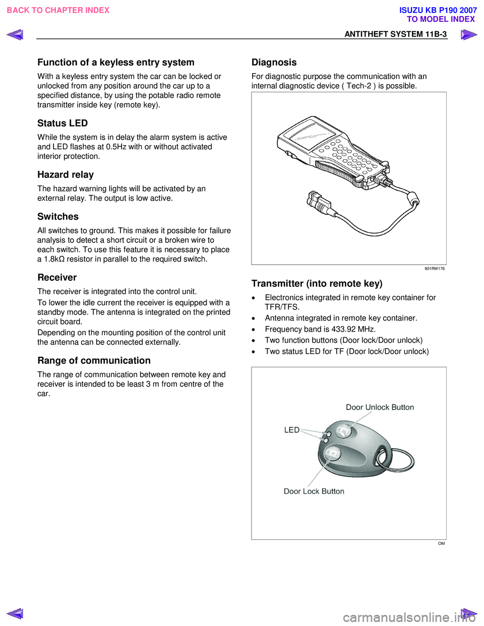
Diagnosis
For diagnostic purpose the communication with an
internal diagnostic device ( Tech-2 ) is possible.
901RW 176
Transmitter (into remote key)
• Electronics integrated in remote key container for
TFR/TFS.
• Antenna integrated in remote key container.
• Frequency band is 433.92 MHz.
• Two function buttons (Door lock/Door unlock)
• Two status LED for TF (Door lock/Door unlock)
OM
BACK TO CHAPTER INDEX TO MODEL INDEX
ISUZU KB P190 2007