vacuum ISUZU KB P190 2007 Workshop User Guide
[x] Cancel search | Manufacturer: ISUZU, Model Year: 2007, Model line: KB P190, Model: ISUZU KB P190 2007Pages: 6020, PDF Size: 70.23 MB
Page 758 of 6020
BRAKES 5C-59
10. Filter
11. Diaphragm
12. Cap
RTW 75CSH002501
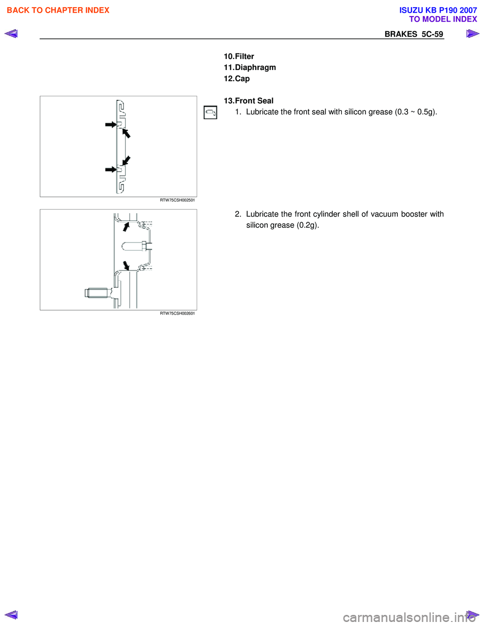
13. Front Seal
1. Lubricate the front seal with silicon grease (0.3 ~ 0.5g).
RTW 75CSH002601
2. Lubricate the front cylinder shell of vacuum booster with
silicon grease (0.2g).
BACK TO CHAPTER INDEX
TO MODEL INDEX
ISUZU KB P190 2007
Page 759 of 6020
5C-60 BRAKES
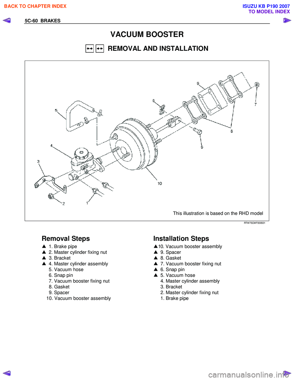
VACUUM BOOSTER
REMOVAL AND INSTALLATION
This illustration is based on the RHD model
RTW 75CMF000501
Removal Steps
▲ 1. Brake pipe
▲ 2. Master cylinder fixing nut
▲ 3. Bracket
▲ 4. Master cylinder assembly
5. Vacuum hose
6. Snap pin
7. Vacuum booster fixing nut
8. Gasket
9. Spacer
10. Vacuum booster assembly
Installation Steps
▲
10. Vacuum booster assembly
▲ 9. Spacer
▲ 8. Gasket
▲ 7. Vacuum booster fixing nut
▲ 6. Snap pin
▲ 5. Vacuum hose
4. Master cylinder assembly
3. Bracket
2. Master cylinder fixing nut
1. Brake pipe
BACK TO CHAPTER INDEX
TO MODEL INDEX
ISUZU KB P190 2007
Page 760 of 6020

BRAKES 5C-61
RTW 75CSH002701
Important Operation-Removal
1. Brake pipe
W hen hurdling, be careful not to spill brake fluid over the
painted surfaces, as damage to the paint finish will result.
2. Master Cylinder Fixing Nut
3. Bracket
4. Master Cylinder Assembly
NOTE:
W hen removing the master cylinder from the vacuum booster,
be sure to get rid of the internal negative pressure of the
vacuum booster (by, for instance, disconnecting the vacuum
hose) in advance.
If any negative pressure remains in the vacuum booster, the
piston may possibly come out when the master cylinder is
being removed, letting the brake fluid run out.
W hile removing the master cylinder, do not hold the piston as it
can be easily pulled out.
Inspection and Repair
Vacuum Hose (The built in check valve)
360R300002
1) Inspect the check valve, which is installed inside the
vacuum hose.
2) Blow air into the hose from the booster side as shown in the illustration. The air should pass freely through the
hose.
3) Blow air into the hose from the engine side. The check valve should close to block the passage of air.
The vacuum hose and built-in check valve must be
replaced as a set if either is found to be defective.
Important Operation-Installation
10. Vacuum Booster Assembly
Note:
•
Adjustment of push rod of vacuum booster is not carried
out. W hen vacuum booster is damaged it exchanges for a
new article. (Push rod is adjusted)
• Measurement of primary piston position by the side o
f
master cylinder is unnecessary.
9. Spacer
8. Gasket
7. Vacuum Booster Fixing Nut
6. Snap Pin
Install the vacuum booster assembly to the dash panel and
pedal mounting bracket.
BACK TO CHAPTER INDEX
TO MODEL INDEX
ISUZU KB P190 2007
Page 761 of 6020

5C-62 BRAKES
360r300003
5. Vacuum Hose
The check valve (2) is built-in to the vacuum hose.
W hen installing the vacuum hose make sure that the arrow on
the hose is facing the engine (1).
Note:
• Do not apply oil to the vacuum hose.
• Installation direction is very important. The booster will not
operate if the vacuum hose is installed in the wrong
direction.
BACK TO CHAPTER INDEX
TO MODEL INDEX
ISUZU KB P190 2007
Page 762 of 6020
BRAKES 5C-63
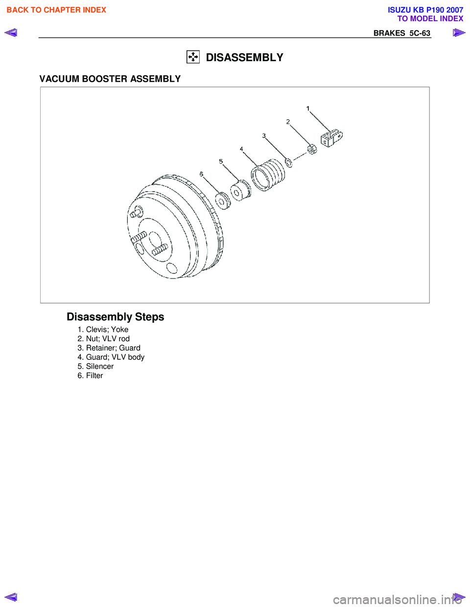
DISASSEMBLY
VACUUM BOOSTER ASSEMBLY
Disassembly Steps
1. Clevis; Yoke
2. Nut; VLV rod
3. Retainer; Guard
4. Guard; VLV body
5. Silencer
6. Filter
BACK TO CHAPTER INDEX
TO MODEL INDEX
ISUZU KB P190 2007
Page 763 of 6020
5C-64 BRAKES
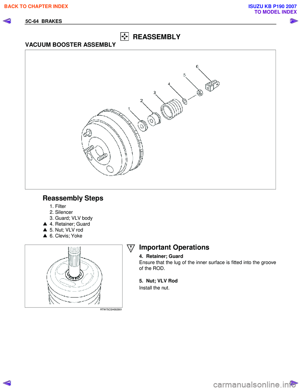
REASSEMBLY
VACUUM BOOSTER ASSEMBLY
Reassembly Steps
1. Filter
2. Silencer
3. Guard; VLV body
▲ 4. Retainer; Guard
▲ 5. Nut; VLV rod
▲ 6. Clevis; Yoke
RTW 75CSH002901
Important Operations
4. Retainer; Guard
Ensure that the lug of the inner surface is fitted into the groove
of the ROD.
5. Nut; VLV Rod
Install the nut.
BACK TO CHAPTER INDEX
TO MODEL INDEX
ISUZU KB P190 2007
Page 764 of 6020
BRAKES 5C-65
RTW 75CSH002801
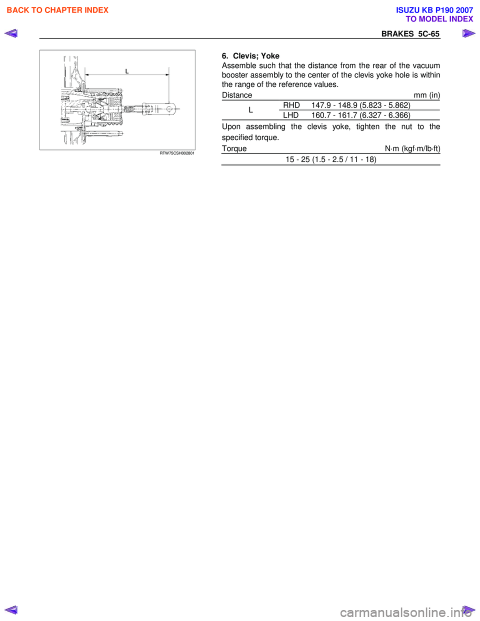
6. Clevis; Yoke
Assemble such that the distance from the rear of the vacuum
booster assembly to the center of the clevis yoke hole is within
the range of the reference values.
Distance mm (in)
RHD 147.9 - 148.9 (5.823 - 5.862)
L LHD 160.7 - 161.7 (6.327 - 6.366)
Upon assembling the clevis yoke, tighten the nut to the
specified torque.
Torque N ⋅m (kgf ⋅m/lb ⋅ft)
15 - 25 (1.5 - 2.5 / 11 - 18)
BACK TO CHAPTER INDEX
TO MODEL INDEX
ISUZU KB P190 2007
Page 787 of 6020
6 – 2 TROUBLESHOOTING
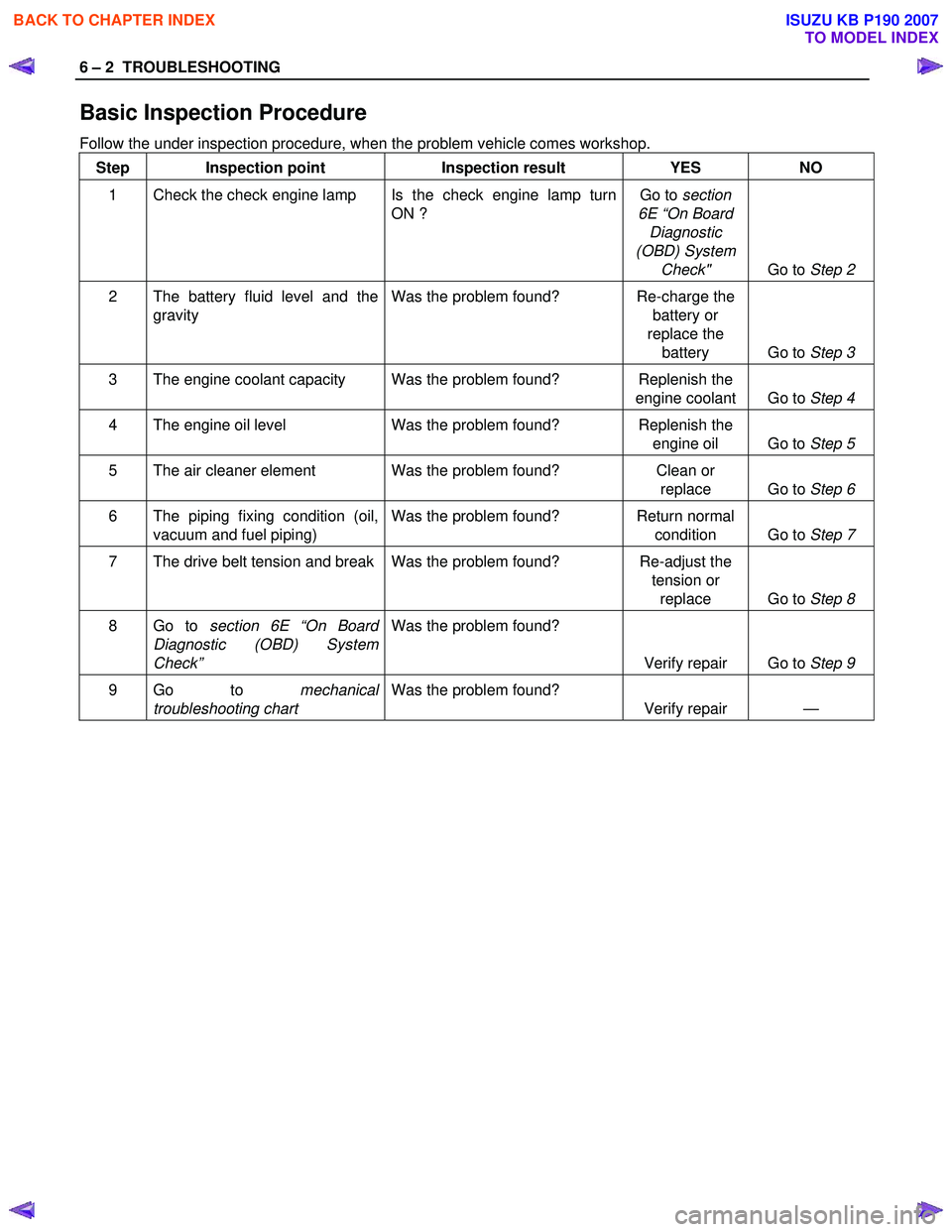
Basic Inspection Procedure
Follow the under inspection procedure, when the problem vehicle comes workshop. Step Inspection point Inspection result YES NO
1 Check the check engine lamp Is the check engine lamp turn ON ? Go to
section
6E “On Board Diagnostic
(OBD) System Check" Go to Step 2
2 The battery fluid level and the
gravity Was the problem found? Re-charge the
battery or
replace the battery Go to Step 3
3 The engine coolant capacity Was the problem found? Replenish the
engine coolant Go to Step 4
4 The engine oil level Was the problem found? Replenish the
engine oil Go to Step 5
5 The air cleaner element Was the problem found? Clean or
replace Go to Step 6
6 The piping fixing condition (oil,
vacuum and fuel piping) Was the problem found? Return normal
condition Go to Step 7
7 The drive belt tension and break Was the problem found? Re-adjust the
tension or replace Go to Step 8
8 Go to section 6E “On Board
Diagnostic (OBD) System
Check” Was the problem found?
Verify repair Go to Step 9
9 Go to mechanical
troubleshooting chart Was the problem found?
Verify repair —
BACK TO CHAPTER INDEX
TO MODEL INDEX
ISUZU KB P190 2007
Page 798 of 6020
TROUBLESHOOTING 6 – 13
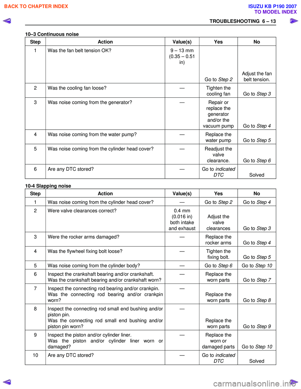
10–3 Continuous noise
Step Action Value(s) Yes No
1 Was the fan belt tension OK? 9 – 13 mm
(0.35 – 0.51
in)
Go to Step 2 Adjust the fan
belt tension.
2 Was the cooling fan loose? — Tighten the
cooling fan Go to Step 3
3 Was noise coming from the generator? — Repair or
replace the generator
and/or the
vacuum pump Go to Step 4
4 Was noise coming from the water pump? — Replace the
water pump Go to Step 5
5 Was noise coming from the cylinder head cover? — Readjust the
valve
clearance. Go to Step 6
6 Are any DTC stored? — Go to indicated
DTC Solved
10-4 Slapping noise
Step Action Value(s) Yes No
1 Was noise coming from the cylinder head cover? — Go to Step 2 Go to Step 4
2 Were valve clearances correct? 0.4 mm
(0.016 in)
both intake
and exhaust Adjust the
valve
clearances Go to Step 3
3 Were the rocker arms damaged? — Replace the
rocker arms Go to Step 4
4 Was the flywheel fixing bolt loose? — Tighten the
fixing bolt. Go to Step 5
5 Was noise coming from the cylinder body? — Go to Step 6 Go to Step 10
6 Inspect the crankshaft bearing and/or crankshaft.
Was the crankshaft bearing and/or crankshaft worn? —
Replace the
worn parts Go to Step 7
7 Inspect the connecting rod bearing and/or crankpin.
Was the connecting rod bearing and/or crankpin
worn? —
Replace the worn parts Go to Step 8
8 Inspect the connecting rod small end bushing and/or
piston pin.
Was the connecting rod small end bushing and/or
piston pin worn? —
Replace the worn parts Go to Step 9
9 Inspect the piston and/or cylinder liner.
Was the piston and/or cylinder liner worn or
damaged? —
Replace the
worn or
damaged parts Go to Step 10
10 Are any DTC stored? — Go to indicated
DTC Solved
BACK TO CHAPTER INDEX
TO MODEL INDEX
ISUZU KB P190 2007
Page 840 of 6020

ENGINE MECHANICAL 6A – 35
Idling Speed Adjustment
1. Loosen the idling set screw lock nut c on the injection
pump idling set bolt.
2. Adjust the idling speed to the specified range by turning the idling set bolt
d.
3. Lock the engine set nut
c with the idling set bolt lock
nut.
4. Check that the idling control cable is tight (free of slack). If required, remove the slack from the cable.
Fast Idling Speed Inspection
1. Set tachometer to the engine.
2. Disconnect the vacuum hose
c from the fast idle
actuator
g on the injection pump.
3. Disconnect the other vacuum hose
d from the
vacuum switching valve
e and connect it to the fast
idle actuator
g.
The vacuum line will now be connected directly from
the vacuum pump
f to the fast idle actuator.
4. Check the engine fast idling speed. If the engine idling speed is outside the specified
range, it must be adjusted.
Fast Idling Speed rpm
850 ± 25
Fast Idling Speed Adjustment
1. Loosen the fast idle actuator bracket bolts.
2. Adjust the fast idling speed by moving the actuator bracket, so that the clearance “S” can be 1 ~ 2 mm
(0.04 ~ 0.08 in.).
3. Tighten the bracket bolts.
Accelerator Control Cable Adjustment
Refer to Sec. 6H-6 (Accelerator Control)
BACK TO CHAPTER INDEX
TO MODEL INDEX
ISUZU KB P190 2007