vacuum ISUZU KB P190 2007 Workshop Repair Manual
[x] Cancel search | Manufacturer: ISUZU, Model Year: 2007, Model line: KB P190, Model: ISUZU KB P190 2007Pages: 6020, PDF Size: 70.23 MB
Page 68 of 6020
1-34 HEATER AND AIR CONDITIONING
REFRIGERANT RECYCLING
Recycle the refrigerant recovered by ACR4 or equivalent.
For the details of the actual operation, follow the steps in the
ACR
4 Manufacturer's Instructions.
ACR4 (115V 60Hz) :5-8840-0629-0 (J-39500-A)
ACR4 (220-240V 50/60Hz)
: 5-8840-0630-0 (J-39500-220A)
ACR
4 (220-240V 50/60Hz Australian model)
: 5-8840-0631-0 (J-39500-220ANZ)
F06R300014
EVACUATION OF THE REFRIGERANT
SYSTEM
NOTE:
Explained below is a method using a vacuum pump. Refer
to the ACR
4 (or equivalent) Manufacturer's Instructions
when evacuating the system with ACR4 (or equivalent).
Air and moisture in the refrigerant will cause problems in the air
conditioning system.
Therefore, before charging the refrigerant, be sure to evacuate
air and moisture thoroughly from the system.
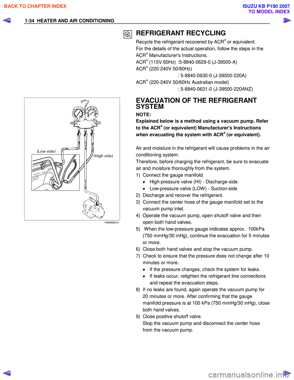
1) Connect the gauge manifold. •
••
•
High-pressure valve (HI) - Discharge-side
•
••
•
Low-pressure valve (LOW ) - Suction-side
2) Discharge and recover the refrigerant.
3) Connect the center hose of the gauge manifold set to the vacuum pump inlet.
4) Operate the vacuum pump, open shutoff valve and then open both hand valves.
5) W hen the low-pressure gauge indicates approx. 100kPa (750 mmHg/30 inHg), continue the evacuation for 5 minutes
or more.
6) Close both hand valves and stop the vacuum pump.
7) Check to ensure that the pressure does not change after 10
minutes or more. •
••
•
If the pressure changes, check the system for leaks.
•
••
•
If leaks occur, retighten the refrigerant line connections
and repeat the evacuation steps.
8) If no leaks are found, again operate the vacuum pump for 20 minutes or more. After confirming that the gauge
manifold pressure is at 100 kPa (750 mmHg/30 inHg), close
both hand valves.
9) Close positive shutoff valve.
Stop the vacuum pump and disconnect the center hose from the vacuum pump.
BACK TO CHAPTER INDEX
TO MODEL INDEX
ISUZU KB P190 2007
Page 125 of 6020
HEATER AND AIR CONDITIONING 1-91
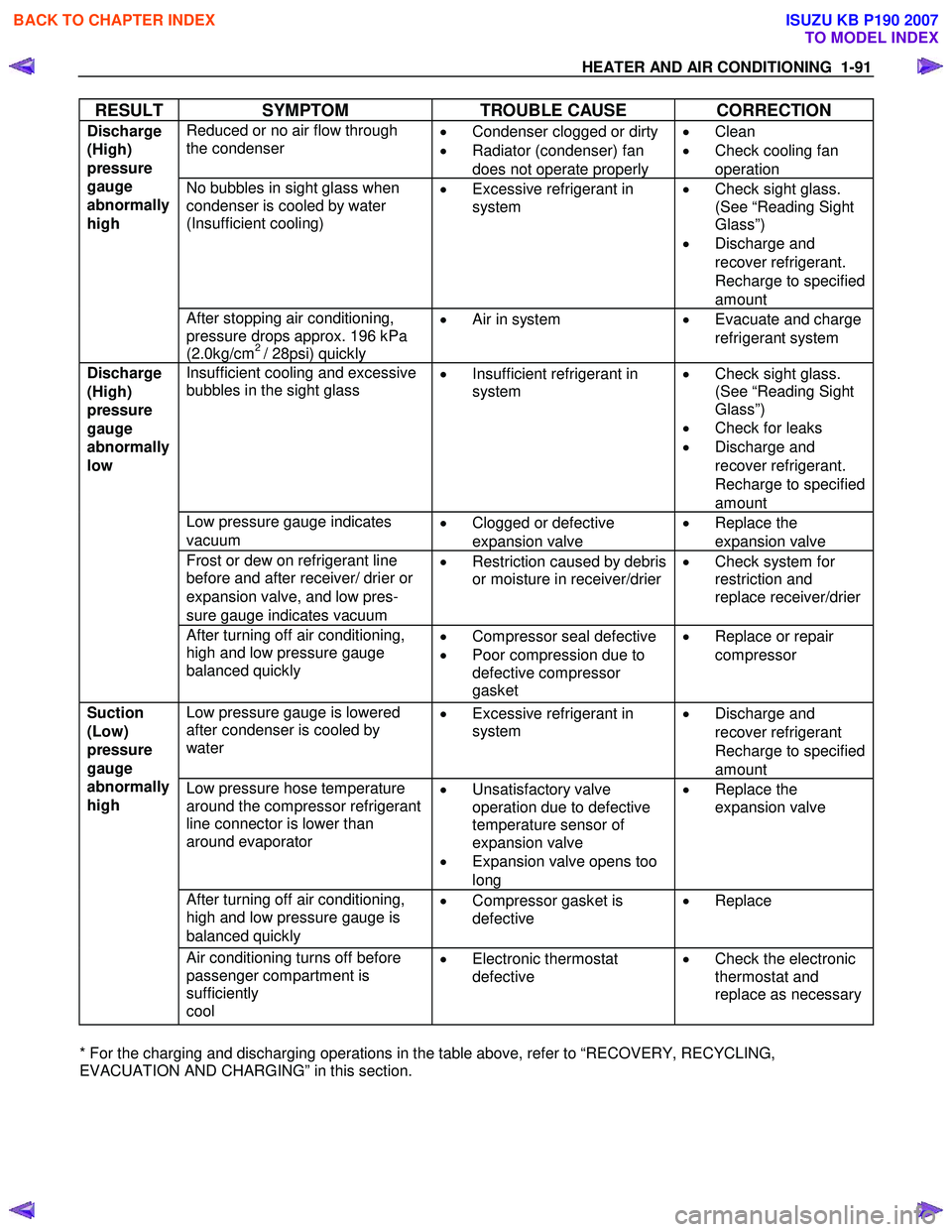
RESULT SYMPTOM TROUBLE CAUSE CORRECTION
Reduced or no air flow through
the condenser
•
Condenser clogged or dirty
• Radiator (condenser) fan
does not operate properly •
Clean
• Check cooling fan
operation
No bubbles in sight glass when
condenser is cooled by water
(Insufficient cooling)
•
Excessive refrigerant in
system
•
Check sight glass.
(See “Reading Sight
Glass”)
• Discharge and
recover refrigerant.
Recharge to specified
amount
Discharge
(High)
pressure
gauge
abnormally
high
After stopping air conditioning,
pressure drops approx. 196 kPa
(2.0kg/cm
2 / 28psi) quickly •
Air in system
•
Evacuate and charge
refrigerant system
Insufficient cooling and excessive
bubbles in the sight glass
•
Insufficient refrigerant in
system
•
Check sight glass.
(See “Reading Sight
Glass”)
• Check for leaks
• Discharge and
recover refrigerant.
Recharge to specified
amount
Low pressure gauge indicates
vacuum •
Clogged or defective
expansion valve •
Replace the
expansion valve
Frost or dew on refrigerant line
before and after receiver/ drier or
expansion valve, and low pres-
sure gauge indicates vacuum •
Restriction caused by debris
or moisture in receiver/drier
•
Check system for
restriction and
replace receiver/drier
Discharge
(High)
pressure
gauge
abnormally
low
After turning off air conditioning,
high and low pressure gauge
balanced quickly
•
Compressor seal defective
• Poor compression due to
defective compressor
gasket •
Replace or repair
compressor
Low pressure gauge is lowered
after condenser is cooled by
water
•
Excessive refrigerant in
system
•
Discharge and
recover refrigerant
Recharge to specified
amount
Low pressure hose temperature
around the compressor refrigerant
line connector is lower than
around evaporator
•
Unsatisfactory valve
operation due to defective
temperature sensor of
expansion valve
• Expansion valve opens too
long •
Replace the
expansion valve
After turning off air conditioning,
high and low pressure gauge is
balanced quickly •
Compressor gasket is
defective
•
Replace
Suction
(Low)
pressure
gauge
abnormally
high
Air conditioning turns off before
passenger compartment is
sufficiently
cool •
Electronic thermostat
defective
•
Check the electronic
thermostat and
replace as necessary
* For the charging and discharging operations in the table above, refer to “RECOVERY, RECYCLING,
EVACUATION AND CHARGING” in this section.
BACK TO CHAPTER INDEX
TO MODEL INDEX
ISUZU KB P190 2007
Page 126 of 6020
1-92 HEATER AND AIR CONDITIONING
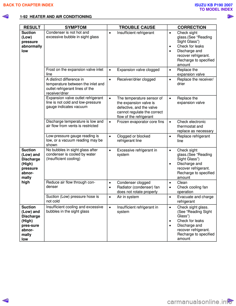
RESULT SYMPTOM TROUBLE CAUSE CORRECTION
Condenser is not hot and
excessive bubble in sight glass
•
Insufficient refrigerant
•
Check sight
glass.(See “Reading
Sight Glass”)
• Check for leaks
• Discharge and
recover refrigerant.
Recharge to specified
amount
Frost on the expansion valve inlet
line •
Expansion valve clogged
•
Replace the
expansion valve
A distinct difference in
temperature between the inlet and
outlet refrigerant lines of the
receiver/drier •
Receiver/drier clogged
•
Replace the receiver/
drier
Expansion valve outlet refrigerant
line is not cold and low-pressure
gauge indicates vacuum
•
The temperature sensor of
the expansion valve is
defective, and the valve
cannot regulate the correct
flow of the refrigerant •
Replace the
expansion valve
Discharge temperature is low and
air flow from vents is restricted
•
Frozen evaporator core fins
•
Check electronic
thermostat and
replace as necessary
Suction
(Low)
pressure
abnormally
low
Low-pressure gauge reading is
low, or a vacuum reading may be
shown •
Clogged or blocked
refrigerant line
•
Replace refrigerant
line
No bubbles in sight glass after
condenser is cooled by water
(Insufficient cooling)
•
Excessive refrigerant in
system
•
Check sight
glass.(See “Reading
Sight Glass”)
• Discharge and
recover refrigerant.
Recharge to specified
amount
Reduce air flow through con-
denser
•
Condenser clogged
• Radiator (condenser) fan
does not rotate properly •
Clean
• Check cooling fan
operation
Suction
(Low) and
Discharge
(High)
pressure
abnor-
mally
high
Suction (Low) pressure hose is
not cold •
Air in system • Evacuate and charge
refrigerant
Suction
(Low) and
Discharge
(High)
pres-sure
abnor-
mally
low Insufficient cooling and excessive
bubbles in the sight glass •
Insufficient refrigerant in
system
•
Check sight glass.
(See “Reading Sight
Glass”)
• Check for leaks
• Discharge and
recover refrigerant.
Recharge to specified
amount
BACK TO CHAPTER INDEX
TO MODEL INDEX
ISUZU KB P190 2007
Page 700 of 6020
BRAKES 5C-1
SECTION 5C
BRAKES
TABLE OF CONTENTS
PAGE
General Description ........................................................................................................ 5C- 2
Main Data and Specifications ......................................................................................... 5C- 9
Torque Specifications ..................................................................................................... 5C-1 0
Servicing ...................................................................................................................... .... 5C-19
Front Disc Brake Assembly ............................................................................................ 5C-33 Removal and Installation............................................................................................ 5C-33
Removal and installation of Disc Pad ....................................................................... 5C-37
Disassembly ................................................................................................................ 5C- 39
Inspection and Repair ................................................................................................ 5C-40
Reassembly ................................................................................................................. 5C- 42
Rear Drum Brake Assembly ........................................................................................... 5C-45 Disassembly ................................................................................................................ 5C- 45
Inspection and Repair ................................................................................................ 5C-46
Reassembly ................................................................................................................. 5C- 48
Brake Control.................................................................................................................. . 5C-52
Removal and Installation............................................................................................ 5C-52
Master Cylinder................................................................................................................ 5C-53
Removal and Installation............................................................................................ 5C-53
Disassembly ................................................................................................................ 5C- 54
Inspection and Repair ................................................................................................ 5C-56
Reassembly ................................................................................................................. 5C- 57
Vacuum Booster .............................................................................................................. 5C -60
Removal and Installation............................................................................................ 5C-60
Disassembly ................................................................................................................ 5C- 63
Reassembly ................................................................................................................. 5C- 64
Special Tools ................................................................................................................. . 5C-70
BACK TO CHAPTER INDEX
TO MODEL INDEX
ISUZU KB P190 2007
Page 707 of 6020
5C-8 BRAKES
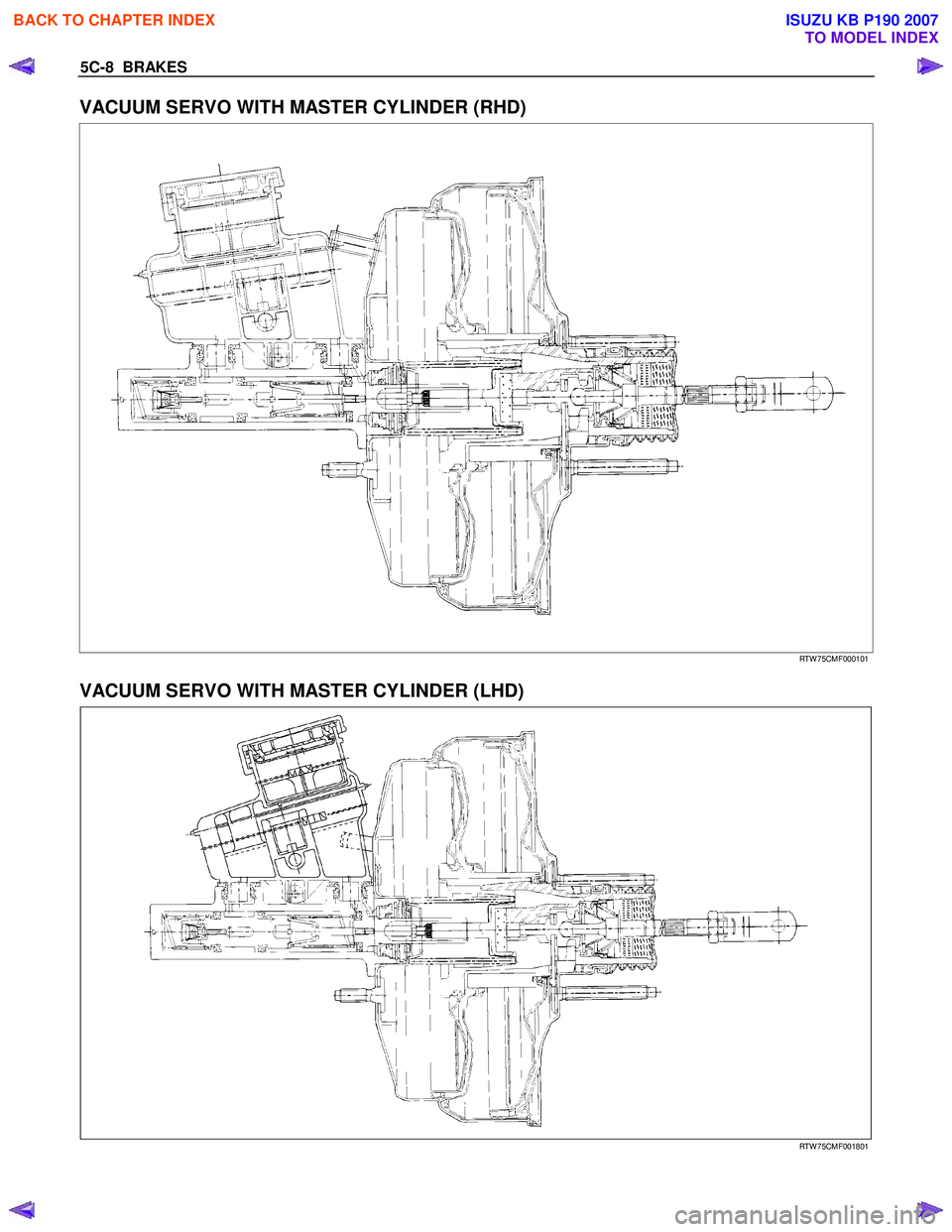
VACUUM SERVO WITH MASTER CYLINDER (RHD)
RTW 75CMF000101
VACUUM SERVO WITH MASTER CYLINDER (LHD)
RTW 75CMF001801
BACK TO CHAPTER INDEX
TO MODEL INDEX
ISUZU KB P190 2007
Page 708 of 6020
BRAKES 5C-9
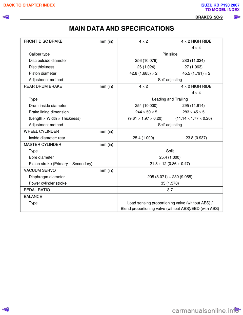
MAIN DATA AND SPECIFICATIONS
FRONT DISC BRAKE mm (in) 4 × 2 HIGH RIDE
4
× 2
4 × 4
Caliper type Pin slide
Disc outside diameter 256 (10.079) 280 (11.024)
Disc thickness 26 (1.024) 27 (1.063)
Piston diameter 42.8 (1.685) × 2 45.5 (1.791) × 2
Adjustment method Self-adjusting
REAR DRUM BRAKE mm (in) 4 × 2 HIGH RIDE
4
× 2
4 × 4
Type Leading and Trailing
Drum inside diameter 254 (10.000) 295 (11.614)
Brake lining dimension 244 × 50 × 5 283 × 45 × 5
(Length × W idth × Thickness) (9.61 × 1.97 × 0.20) (11.14 × 1.77 × 0.20)
Adjustment method Self-adjusting
W HEEL CYLINDER mm (in)
Inside diameter: rear 25.4 (1.000) 23.8 (0.937)
MASTER CYLINDER mm (in)
Type Split
Bore diameter 25.4 (1.000)
Piston stroke (Primary + Secondary) 21.8 + 12 (0.86 + 0.47)
VACUUM SERVO mm (in)
Diaphragm diameter 205 (8.071) + 230 (9.055)
Power cylinder stroke 35 (1.378)
PEDAL RATIO 3.7
BALANCE
Type Load sensing proportioning valve (without ABS) /
Blend proportioning valve (without ABS)/EBD (with ABS)
BACK TO CHAPTER INDEX
TO MODEL INDEX
ISUZU KB P190 2007
Page 711 of 6020
5C-12 BRAKES
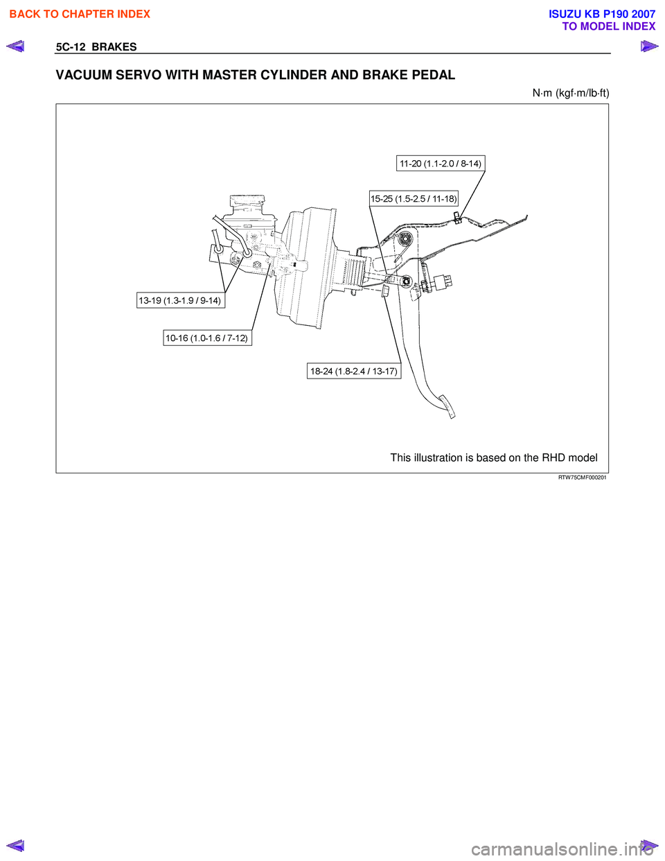
VACUUM SERVO WITH MASTER CYLINDER AND BRAKE PEDAL
N ⋅m (kgf ⋅m/lb ⋅ft)
This illustration is based on the RHD model
RTW 75CMF000201
BACK TO CHAPTER INDEX
TO MODEL INDEX
ISUZU KB P190 2007
Page 725 of 6020
5C-26 BRAKES
A bleeding operation is necessary to remove air from the
hydraulic brake system whenever air is introduced into the
hydraulic system. It may be necessary to bleed the hydraulic
system at all four brakes if air has been introduced through a
low fluid level or by disconnecting brake pipes at the maste
r
cylinder. If a brake pipe is disconnected at one wheel, only that
wheel cylinder/caliper needs to be bled. If the pipes are
disconnected at any fitting located between the master cylinde
r
and brakes, then the brake system served by the disconnected
pipe must be bled.
1. Set the parking brake completely, then start the engine.
NOTE:
The vacuum booster will be damaged if the bleeding operation
is performed with the engine off.
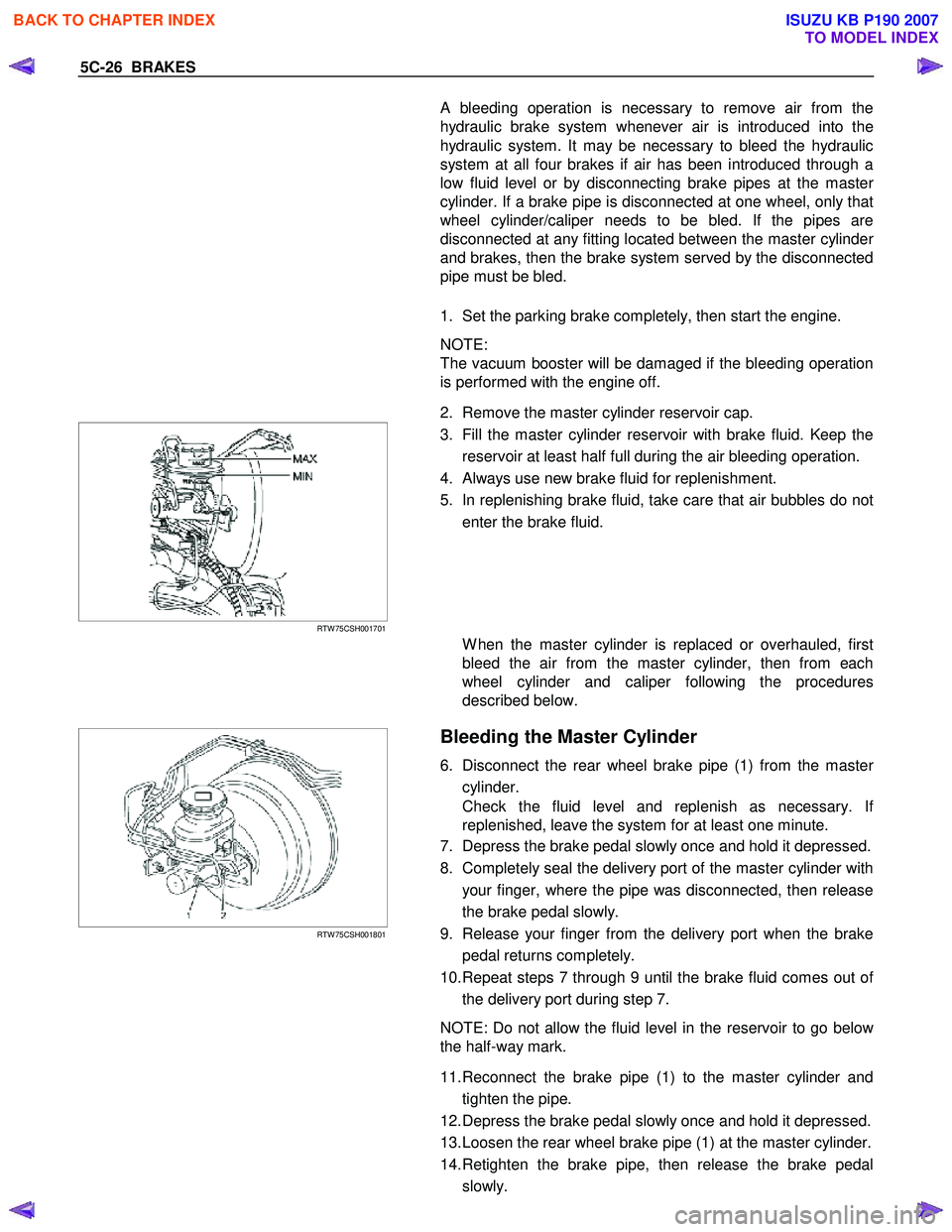
2. Remove the master cylinder reservoir cap.
RTW 75CSH001701
3. Fill the master cylinder reservoir with brake fluid. Keep the
reservoir at least half full during the air bleeding operation.
4. Always use new brake fluid for replenishment.
5. In replenishing brake fluid, take care that air bubbles do not enter the brake fluid.
W hen the master cylinder is replaced or overhauled, first
bleed the air from the master cylinder, then from each
wheel cylinder and caliper following the procedures
described below.
RTW 75CSH001801
Bleeding the Master Cylinder
6. Disconnect the rear wheel brake pipe (1) from the master
cylinder.
Check the fluid level and replenish as necessary. I
f
replenished, leave the system for at least one minute.
7. Depress the brake pedal slowly once and hold it depressed.
8. Completely seal the delivery port of the master cylinder with your finger, where the pipe was disconnected, then release
the brake pedal slowly.
9. Release your finger from the delivery port when the brake pedal returns completely.
10. Repeat steps 7 through 9 until the brake fluid comes out o
f
the delivery port during step 7.
NOTE: Do not allow the fluid level in the reservoir to go belo
w
the half-way mark.
11. Reconnect the brake pipe (1) to the master cylinder and tighten the pipe.
12. Depress the brake pedal slowly once and hold it depressed.
13. Loosen the rear wheel brake pipe (1) at the master cylinder.
14. Retighten the brake pipe, then release the brake pedal slowly.
BACK TO CHAPTER INDEX
TO MODEL INDEX
ISUZU KB P190 2007
Page 752 of 6020
BRAKES 5C-53
MASTER CYLINDER
REMOVAL AND INSTALLATION
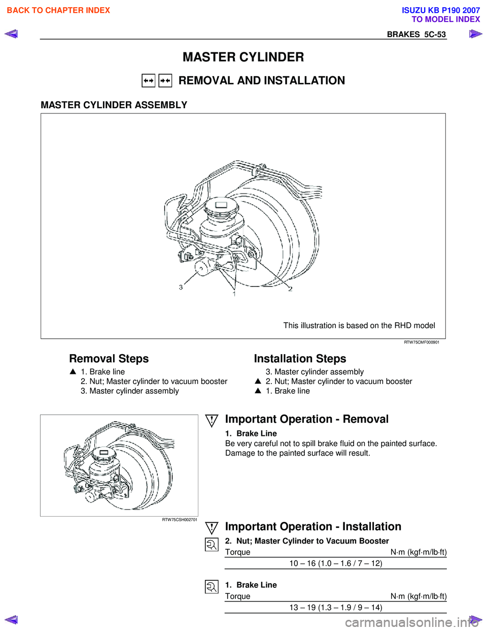
MASTER CYLINDER ASSEMBLY
This illustration is based on the RHD model
RTW 75CMF000901
Removal Steps
▲ 1. Brake line
2. Nut; Master cylinder to vacuum booster
3. Master cylinder assembly
Installation Steps
3. Master cylinder assembly
▲ 2. Nut; Master cylinder to vacuum booster
▲ 1. Brake line
RTW 75CSH002701
Important Operation - Removal
1. Brake Line
Be very careful not to spill brake fluid on the painted surface.
Damage to the painted surface will result.
Important Operation - Installation
2. Nut; Master Cylinder to Vacuum Booster
Torque N ⋅m (kgf ⋅m/lb ⋅ft)
10 – 16 (1.0 – 1.6 / 7 – 12)
1. Brake Line
Torque N ⋅m (kgf ⋅m/lb ⋅ft)
13 – 19 (1.3 – 1.9 / 9 – 14)
BACK TO CHAPTER INDEX
TO MODEL INDEX
ISUZU KB P190 2007
Page 754 of 6020
BRAKES 5C-55
Important Operations
W hen disassembling, inspecting or reassembling the master
cylinder assembly, take care not to bring the parts into contact
with mineral oil or dust. W ash the piston cups only with brake
fluid. Do not use gasoline or other mineral-base cleaning
solvents.
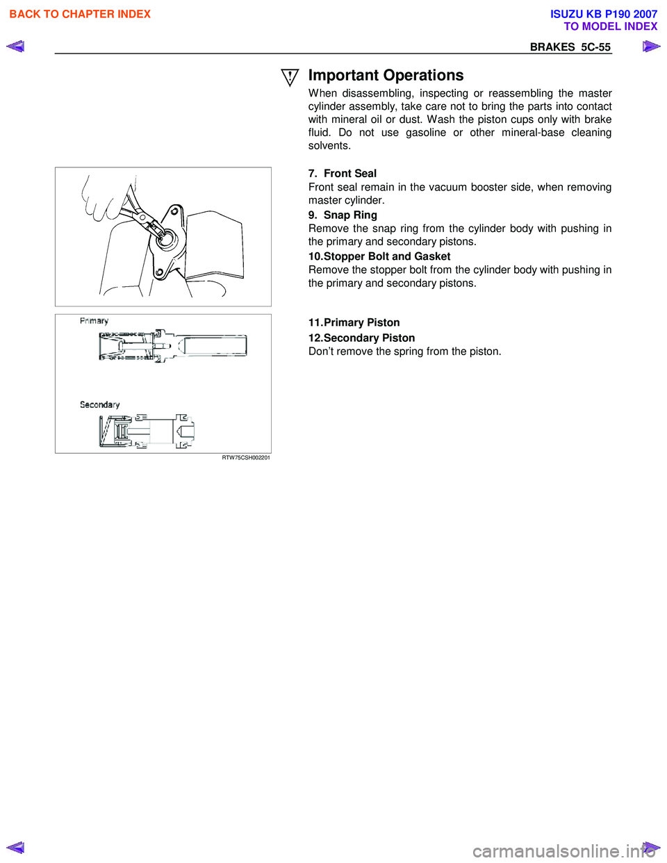
7. Front Seal
Front seal remain in the vacuum booster side, when removing
master cylinder.
9. Snap Ring
Remove the snap ring from the cylinder body with pushing in
the primary and secondary pistons.
10. Stopper Bolt and Gasket
Remove the stopper bolt from the cylinder body with pushing in
the primary and secondary pistons.
RTW 75CSH002201
11. Primary Piston
12. Secondary Piston
Don’t remove the spring from the piston.
BACK TO CHAPTER INDEX
TO MODEL INDEX
ISUZU KB P190 2007