engine mount ISUZU KB P190 2007 Workshop Repair Manual
[x] Cancel search | Manufacturer: ISUZU, Model Year: 2007, Model line: KB P190, Model: ISUZU KB P190 2007Pages: 6020, PDF Size: 70.23 MB
Page 2832 of 6020
Engine Mechanical – V6 Page 6A1–55
Page 6A1–55
Drive Belt Squeal
Definition
Accessory drive belt squealing can be defined as a loud screeching noise caused by a slipping drive belt. Belt squeal is
unusual in multi-rib belts. Drive belt squeal generally occurs when a heavy load is applied to the drive belt, such as an
air-conditioning compressor engagement, snapping the throttle, se ized pulley or a faulty accessory drive component.
Diagnostic Aids
If the noise is intermittent, confirm the accessory drive components by varying t heir loads, making sure they are operated
to their maximum capacity. An overcharged A/C system, restrictions in the power steering pressure circuit or a faulty
generator or coolant pump are likely c auses of accessory drive belt squeal.
A loose or incorrectly installed body component, suspension component or other item may be the cause of the noise.
Test Description
The numbers below refer to steps in the diagnostic table.
2 The noise may not be engine related. This step is to confirm the engine is making t he noise. If the engine is not
making the noise, do not proceed further with this diagnostic procedure.
3 The noise may be an internal engine noise. Removing the drive belt and operating the engine briefly will confirm
whether or not the noise is related to the drive belt.
CAUTION
When running the engine with the accessory
drive belt removed, the coolant pump will not
be operating and the engine may overheat if
left unsupervised even for a short period.
NOTE
There may also be a number of DTCs set when
running the engine with the accessory drive belt
removed.
4 Confirms an accessory drive component does not have a se ized bearing. With the belt removed, test the bearings
in the accessory drive co mponents spin free and smooth.
5 Confirms the drive belt tensioner is operating correctly. If the drive belt tensioner is not operating correctly, drive
belt tension will not be maintained, resulting in a belt squealing noise
6 Confirms the belt is not too long, which would prevent the tensioner from working as intended. Also, if an
excessively long belt has been fitted, it may also be r outed incorrectly and may be turning an accessory drive
component in the wrong direction.
7 Misalignment of the pulleys may be caused by one of the following:
• Incorrect mounting of an accessory drive component,
• Incorrect installation of an accessory drive pulley or,
• Bent or damaged pulley.
Test for a misaligned pulley using a straight edge in the pulley grooves across 2 or 3 pulleys. If a misaligned pulley is found, refer to the relevant component service info rmation for the correct installation and removal procedures.
8 This test is to confirm the pulleys are the correct di ameter and/or width. Using a known good vehicle, compare the
pulley sizes.
Diagnostic Table
Step Action Yes No
1
Did you review the information provided in 2.2 Symptoms, and
perform the required inspections. Go to Step 2 Go to
2.2 Symptoms
2 Confirm the customer compla int. Is there a squealing noise?
Go to Step 3 Refer to Diagnostic
Aids in this Section
BACK TO CHAPTER INDEX
TO MODEL INDEX
ISUZU KB P190 2007
Page 2835 of 6020
Engine Mechanical – V6 Page 6A1–58
Page 6A1–58
Drive Belt Rumble
Definition
Accessory drive belt rumble can be defined as a low pitch tapping, knocking or thumping noise heard at or just above
idle, once per rotation of the drive belt or a specific co mponent. Drive belt rumble is generally caused by one of the
following:
• pilling or strings in the drive belt grooves,
• separation of the drive belt, or
• a damaged or faulty drive belt.
NOTE
Pilling is the small balls (p ills) or strings of rubber
in the belt grooves caused by the accumulation of
rubber dust.
Diagnostic Aids
Vibration from the engine may cause a body component or other parts to emit a rumbling noise.
The drive belt may have a condition that cannot be seen or felt. Sometimes the replacement of the belt may be the only
way to confirm the belt is faulty.
If the drive belt has been replaced and the di agnostic table completed, but the rumble is still present only when the drive
belt is installed, an accessory drive component such as t he A/C compressor may be the cause. Varying the load to each
accessory drive component in turn, should help isolate which component is causing the noise.
Test Description
The numbers below refer to steps in the diagnostic table.
2 Confirms the symptom exists at the time of di agnosis. Other vehicle components may be causing the noise.
3 Confirms the accessory drive belt is the cause of the noise. Drive belt rumbling is often confused with an internal
engine noise due to the similarity in the description. Removing the drive belt and operating the engine briefly will
confirm whether or not the noise is related to the drive belt.
CAUTION
When running the engine with the accessory
drive belt removed, the coolant pump will not
be operating and the engine may overheat if
left unsupervised even for a short period.
NOTE
There may also be a number of DTCs set when
running the engine with the accessory drive belt
removed.
4 Inspecting the drive belt is to ensure t hat it is not causing the noise. Small cracks across the ribs of the drive belt
will not cause the noise and are not just ification alone to replace the belt. Belt separation can be identified by the
ply of the belt separating and may be seen at the edge of the belt or felt as lumps under the belt.
5 Small amounts of pilling is a normal condition and is deemed acceptable. When the pilling is severe (33% of the
belt groove depth), the belt does not have a smoot h surface to run on and should be replaced.
Diagnostic Table
Step Action Yes No
1
Did you review the information provided in 2.2 Symptoms, and
perform the required inspections. Go to Step 2 Go to
2.2 Symptoms
2 Confirm the customer compla int. Is there a rumbling noise?
Go to Step 3 Refer to Diagnostic
Aids in this Section
3 1 Remove the drive belt, refer to 3.5 Accessory Drive Belt.
2 Operate the engine for no more than 40 seconds.
Does the rumbling noise still exist? Accessory drive
system OK
Go to 2.2
Symptoms, and
restart the diagnosis Go to Step 4
BACK TO CHAPTER INDEX
TO MODEL INDEX
ISUZU KB P190 2007
Page 2838 of 6020
Engine Mechanical – V6 Page 6A1–61
Page 6A1–61
Step Action Yes No
6 Inspect for incorrect, loose, missing or damaged fasteners.
Did you find any incorrect, loose, missing or damaged fasteners? Go to Step 7 Go to Step 8
7
Tighten any loose fasteners to the corre ct torque specification, refer to
6 Torque Wrench Specifications.
Replace any incorrect or missing fasteners.
Did you complete the repairs? Go to Step 10 —
8
Inspect the coolant pump for a bent shaft, refer to 6B1 Engine Cooling
– V6.
Did you find and repair a bent coolant pump shaft? Go to Step 10 Go to Step 9
9
Inspect for bent, cracked or damaged accessory drive component
mounting brackets.
Did you find and repair any bent brackets? Go to Step 10 Refer to Diagnostic
Aids in this Section
10 If required, reinstall the accessory drive belt and operate the system to
confirm the repair.
Did you correct the vibration? Accessory drive
system OK Refer to Diagnostic
Aids in this Section
BACK TO CHAPTER INDEX
TO MODEL INDEX
ISUZU KB P190 2007
Page 2839 of 6020
Engine Mechanical – V6 Page 6A1–62
Page 6A1–62
Drive Belt Falls Off
Definition
The drive belt falls off during normal operation or does not ride correctly on the accessory drive pulleys.
Diagnostic Aids
If the accessory drive belt repeatedly falls off the drive pulleys, this is most likely due to pulley misalignment.
An extra load that is quickly applied and released by an a ccessory drive component (e.g. A/C compressor) may cause
the accessory drive belt to fall off. In th is circumstance, confirm the fault by operating the accessory drive components in
turn, noting which one caused the belt to fall off.
Lack of drive belt tension may also cause the belt to fall o ff the pulleys. Low drive belt tension could be caused by one of
the following:
• an incorrect drive belt length,
• a faulty drive belt tensioner, or
• a stretched or faulty drive belt.
Test Description
The numbers below refer to steps in the diagnostic table.
2 Confirms the condition of t he drive belt. Damage may have occurred to the dr ive belt when it first fell off or it may
have been damaged which caused the belt to fall off.
4 Misalignment of the pulleys may be caused by:
• the incorrect installation or mount ing of an accessory drive component,
• the incorrect installation of an a ccessory drive component pulley, or
• a damaged or bent accessory drive pulley.
Test for a misaligned pulley using a suitable straight edge in the pulley grooves across two or more pulleys. If a
misaligned pulley is found, refer to the service informa tion for the particular component, for the correct pulley
replacement procedures.
5 Inspecting the pulleys should include an inspection for dents or other damage that would prevent the drive belt from
seating correctly in all of the pulley grooves or on the smooth surface of a pulley when the back side of the belt is
used.
6 Accessory drive component mounting brackets that are bent will cause the drive belt to fall off.
7 Inspection of the fasteners can eliminat e the possibility that an incorrect fastener was installed. Missing, loose or
incorrect fasteners may cause pulley misalignment from the fasteners moving under load. Over-tightening of the
fasteners may cause deflection of mounting brackets and result in misaligned accessory drive pulleys.
Diagnostic Table
Step Action Yes No
1
Did you review the information provided in 2.2 Symptoms, and
perform the required inspections. Go to Step 2 Go to
2.2 Symptoms
2 Inspect for a damaged accessory drive belt.
Did you find any damage on the drive belt? Go to Step 3 Go to Step 4
3 Install a new accessory drive belt, re
fer to 3.5 Accessory Drive Belt.
Does the drive belt continue to fall off? Go to Step 4 Go to Step 12
4 Inspect the accessory drive system pulleys for misalignment
Did you find and repair any misaligned drive system pulleys? Go to Step 12 Go to Step 5
5 Inspect for a dented or cracked accessory drive system pulley.
Did you find and repair any dented or cracked drive system? Go to Step 12 Go to Step 6
6 Inspect for bent accessory drive component mounting brackets.
Did you find and repair any bent mounting brackets? Go to Step 12 Go to Step 7
7 Inspect for incorrect, loose, missing or damaged fasteners.
Did you find any incorrect, loose, missing or damaged fasteners? Go to Step 8 Go to Step 9
BACK TO CHAPTER INDEX
TO MODEL INDEX
ISUZU KB P190 2007
Page 2844 of 6020

Engine Mechanical – V6 Page 6A1–67
Page 6A1–67
Replace
NOTE
• Quicker and more complete draining will
occur if the engine oil is at normal operating
temperature. However, care must be taken to
avoid scalding from the hot oil.
• It recommended the oil filter be changed at
each engine oil change, refer to 3.2 Oil Filter.
1 Remove the oil fill cap.
2 To ensure complete draining of the oil pan, raise the front and rear of the vehicle to maintain a level attitude. If not
using a hoist, support the vehicle with safety stands, refer to Section 0A General Information.
3 Clean any foreign material from around the oil drain pl ug and place a suitable, clean drain tray under the engine.
The oil may be hot. Avoid contact with the oil.
Ensure that eyes and skin are protected.
4 Remove the drain plug (1), taking care to avoid sca lding from the hot oil. Allow the oil to drain.
5 Clean and inspect the drain plug threads . If damaged, replace the drain plug.
Figure 6A1 – 24
6 Once the oil has completely drained, reinstall the dr ain plug and tighten to the correct torque specification.
Oil pan drain plug
torque specificat ion ............................................ 25.0 Nm
7 Replace the oil filter, refer to 3.2 Oil Filter.
8 Lower the vehicle to the ground and fill with the specified amount of SAE 5W30 lubricant.
Engine Oil Capacity:
With Oil Filter Change........................................6.5 litres
9 Install the oil fill cap.
10 Start the engine and check for leaks.
BACK TO CHAPTER INDEX
TO MODEL INDEX
ISUZU KB P190 2007
Page 2856 of 6020

Engine Mechanical – V6 Page 6A1–79
Page 6A1–79
8 Disconnect the wiring harness connector from the
barometric (BARO) pressure sensor (1).
Figure 6A1 – 37
9 Disconnect the PCV tube connector (1) from the upper intake manifold assembly.
Figure 6A1 – 38
10 Remove the bolt (3) attaching the EVAP valve and the fuel injector wiring harness connector mounting
bracket to the upper inta ke manifold assembly.
11 Move the EVAP valve and the fuel injector wiring harness connector mounting br acket clear of the upper
intake manifold assembly.
12 Disconnect the PCV fresh air tube (1) from its upper intake manifold mounting clip (2).
Figure 6A1 – 39
BACK TO CHAPTER INDEX
TO MODEL INDEX
ISUZU KB P190 2007
Page 2863 of 6020
Engine Mechanical – V6 Page 6A1–86
Page 6A1–86
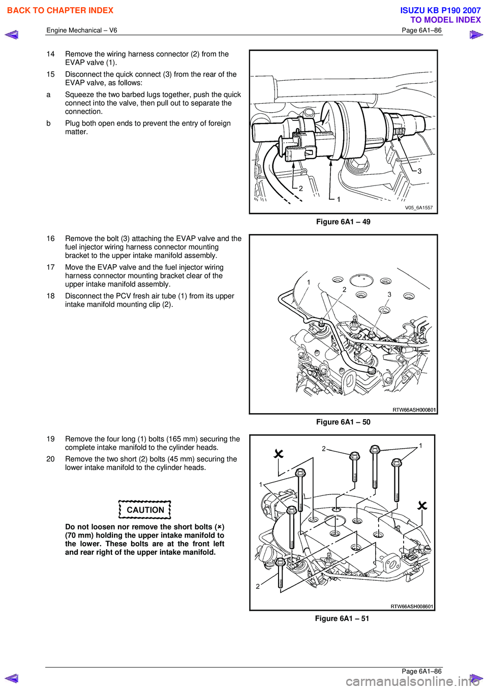
14 Remove the wiring harness connector (2) from the
EVAP valve (1).
15 Disconnect the quick connect (3 ) from the rear of the
EVAP valve, as follows:
a Squeeze the two barbed lugs together, push the quick
connect into the valve, t hen pull out to separate the
connection.
b Plug both open ends to prevent the entry of foreign
matter.
Figure 6A1 – 49
16 Remove the bolt (3) attaching the EVAP valve and the fuel injector wiring harness connector mounting
bracket to the upper inta ke manifold assembly.
17 Move the EVAP valve and the fuel injector wiring harness connector mounting bracket clear of the
upper intake manifold assembly.
18 Disconnect the PCV fresh air tube (1) from its upper intake manifold mounting clip (2).
Figure 6A1 – 50
19 Remove the four long (1) bolts (165 mm) securing the complete intake manifo ld to the cylinder heads.
20 Remove the two short (2) bolts (45 mm) securing the lower intake manifold to the cylinder heads.
Do not loosen nor remove the short bolts ( �8)
(70 mm) holding the upper intake manifold to
the lower. These bolts are at the front left
and rear right of the upper intake manifold.
Figure 6A1 – 51
BACK TO CHAPTER INDEX
TO MODEL INDEX
ISUZU KB P190 2007
Page 2870 of 6020

Engine Mechanical – V6 Page 6A1–93
Page 6A1–93
Inspect
Inspect the exhaust manifold (1) for the following:
• Damage to the threaded holes for the heat shield
mounting.
• Damage to the exhaust manifold mounting holes.
• Damage to the threads of the exhaust manifold to
exhaust pipe flange studs.
• Damage to the gasket sealing surfaces.
• Using a straight edge (2) and feeler gauges (3), check
the cylinder head mounting face of the exhaust
manifold does not exceed the maximum distortion
specification of 0.25mm.
NOTE
If the surface flatness is not within
specifications, the exhaus t manifold is warped
and must be replaced.
Figure 6A1 – 60
Reinstall
Reinstallation of the exhaust manifold assembly is the reverse of the removal procedure, noting the following:
1 Ensure the exhaust manifold, cylinder head and exhaust pipe flange surfaces are clean.
2 Position a new exhaust manifold gasket onto the exhaust manifold.
3 Apply a 5 mm bead of Loctite 272 thread sealant (or equival ent) to the threads of the exhaust manifold attaching
bolts.
4 Install the bolts into the exhaust manifold. This will prevent the gasket from falling off the manifold.
5 Manoeuvre the exhaust manifold into position and install the exhaust manifold attaching bolts.
6 From underneath the vehicle install the exhaust manifold to exhaust pipe flange nuts.
7 Tighten the exhaust manifold attaching bolts to the correct torque specification.
NOTE
When tightening the exhaust manifold to cylinder
head attaching bolts, begin with the centre bolts,
then alternate from side to side to the outer bolts.
Exhaust manifold to cylinder head
attaching bolt torque spec ification ........... 17.0 – 23.0 Nm
8 Apply an anti seize compound such as Caltex Kopr-Kot e (or equivalent) to the cleaned heat shield bolt threads.
Install the heat shield attaching bolts and ti ghten to the correct torque specification.
Exhaust manifold heat shield attaching
bolt torque specificat ion ............................ 8.0 – 12.0 Nm
9 For the right-hand side, install the battery harness ground cable attaching nut through the ground terminal and
lower coolant tube mounting lug, and tighten to the correct torque specification.
Battery harness ground terminal
attaching nut torque s pecification.......................13.0 Nm
BACK TO CHAPTER INDEX
TO MODEL INDEX
ISUZU KB P190 2007
Page 2881 of 6020

Engine Mechanical – V6 Page 6A1–104
Page 6A1–104
3.15 Front Cover Assembly
Remove
1 Drain the engine coolant, refer to Section 6B1 Engine Cooling.
2 Remove the water outlet pipe and coolant pump assembly, refer to Section 6B1 Engine Cooling:
3 Remove the camsha ft covers, refer to 3.12 Camshaft Cover .
4 Remove the crankshaft bal ancer assembly, refer to 3.13 Crankshaft Balancer Assembly .
5 Disconnect the purge vent hose from the water outlet pipe.
NOTE
Do not disconnect the power steering pipes or
drain the power steering fluid.
6 Remove the power steering pump reservoir mounting bracket, refer to 3.8 Power Steering Pump Bracket.
7 Remove the camshaft position sensor, refer to Section 6C1-3 Engine Management – V6 – Service Operations.
NOTE
Do not disconnect the A/C compressor pipes.
8 Remove the bolt (2), 22 places, attaching the front cover assembly (1).
CAUTION
Only use the prise points and a bolt in the
jackscrew hole to remove the engine front
cover.
9 Loosely install a 10 x 1.5 mm bolt in the jackscrew hole (1).
10 Using the prise points (2) located at the edge of the
front cover and the jackscrew, shear the RTV sealant.
Figure 6A1 – 83
Figure 6A1 – 84
BACK TO CHAPTER INDEX
TO MODEL INDEX
ISUZU KB P190 2007
Page 2895 of 6020
Engine Mechanical – V6 Page 6A1–118
Page 6A1–118
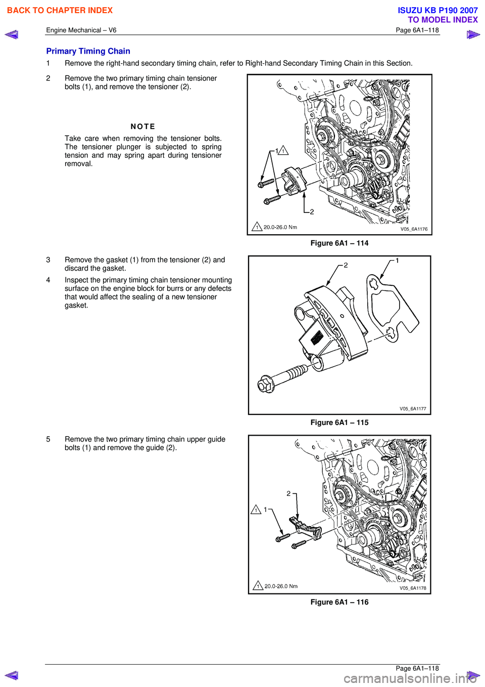
Primary Timing Chain
1 Remove the right-hand secondary timing chain, refer to Right-hand Secondary Timing Chain in this Section.
2 Remove the two primary timing chain tensioner bolts (1), and remove the tensioner (2).
NOTE
Take care when removing the tensioner bolts.
The tensioner plunger is subjected to spring
tension and may spring apart during tensioner
removal.
Figure 6A1 – 114
3 Remove the gasket (1) from the tensioner (2) and discard the gasket.
4 Inspect the primary timi ng chain tensioner mounting
surface on the engine block for burrs or any defects
that would affect the s ealing of a new tensioner
gasket.
Figure 6A1 – 115
5 Remove the two primary timing chain upper guide bolts (1) and remove the guide (2).
Figure 6A1 – 116
BACK TO CHAPTER INDEX
TO MODEL INDEX
ISUZU KB P190 2007