engine mount ISUZU KB P190 2007 Workshop Repair Manual
[x] Cancel search | Manufacturer: ISUZU, Model Year: 2007, Model line: KB P190, Model: ISUZU KB P190 2007Pages: 6020, PDF Size: 70.23 MB
Page 2677 of 6020
Engine Mechanical – V6 Page 6A1–198
k Timing chains, tensioners, shoes, guides & sprockets, refer to 3.16 Timing Chains, Tensioners, Shoes and
Guides.
l Cylinder head assemblies, refer to 3.22 Cylinder Head Assembly.
m Oil pan assembly, refer to 4.2 Oil Pan and Oil Pump Suction Pipe Assembly.
n Piston and connecting rod assemblies, refer to 4.5 Pistons, Pins, Rings, Connecting Rods and Big-end Bearings.
o Crankshaft assembly, refer to 4.6 Crankshaft and Main Bearings.
p Piston oil nozzles, refer 4.5 Pistons, Pins, Rings, Connecting Rods and Big-end Bearings.
Reassemble
Reassembly of the engine assembly is the reverse of the disassembly procedure.
Reinstall
Reinstallation of the engine assembly is the reverse to the removal procedure, noting the following:
NOTE
Refer to 6 Torque Wrench Specifications
for the correct torque specifications.
1 Tighten the fasteners to the correct torque specification.
Engine ground connector bolt
torque specification ............................................10.0 Nm
Power steering high pressure line
attaching bolt torque specification .............8.0 – 12.0 Nm
Power steering high pressure line
flare nut torque specification ...................25.0 – 35.0 Nm
Engine mount to frame attaching bolt
torque specification .................................44.0 – 60.0 Nm
Knock Sensor Attaching Nut
torque specification ............................................23.0 Nm
2 Use only the specified engine lubricant type and quantity. It is recommended that a fluorescent oil dye, such as that contained in J 28481-B, be added to assist in any future oil leak diagnosis.
3 Fill the cooling system with the correct quantity and grade of coolant, refer to 6B1 Engine Cooling – V6.
4 Check transmission fluid level, replenishing as required, using the specified lubricant for the transmission fitted, refer to 7C1 Automatic – 4L60E – General Information.
5 Disable the ignition system, refer to 6C1-3 Engine Management – V6 – Service Operations.
6 Crank the engine several times. Listen for any unusual noises or evidence that parts are binding.
7 Enable the ignition system. Start the engine and listen for any unusual noises.
8 Check the vehicle oil pressure gauge or warning indicator and confirm the engine has acceptable oil pressure. If required, install an oil pressure gauge and measure the engine oil pressure, refer to 2.19 Engine Oil Pressure
Diagnosis.
9 Run the engine at about 1,000 r.p.m. until the engine has reached normal operating temperature.
10 Listen for any unusual noises.
11 Check for oil, fuel, coolant and exhaust leaks while the engine is running, correcting as required.
12 Perform a final inspection for correct engine oil and coolant levels.
4.2 Oil Pan and Oil Pump Suction Pipe Assembly
Remove
1 Remove the engine assembly from the vehicle, refer to 4.1 Engine .
2 Separate the engine and transmission assemblies, refer to 7C1 Automatic – 4L60E – General Information.
3 Mount the engine assembly on a suitable engine stand.
4 Remove the engine front cover, refer to 3.15 Front Cover Assembly.
BACK TO CHAPTER INDEX
TO MODEL INDEX
ISUZU KB P190 2007
Page 2680 of 6020

Engine Mechanical – V6 Page 6A1–201
Inspect
1 Inspect the exterior of the oil pan for the following
conditions:
• Damage to the drain plug or drain plug hole,
• Damage to the transmission mounting bosses,
• Damage to the oil level sensor threads, and
• Dents or damage to the exterior.
2 Inspect the interior of the oil pan for the following conditions:
• Gouges or damage to the oil pan sealing
surfaces,
• Damage to the crankshaft oil deflector,
• Damage to the bolt holes,
• Damage to the oil suction tube mounting
bosses, and
• Damage to the crankshaft oil deflector mounting
bosses.
Figure 6A1 – 355
3 Inspect the oil pan deflector for damage.
4 Repair or replace the oil pan deflector and/or oil pan as required.
Figure 6A1 – 356
5 Inspect the following:
6 The mounting face (1) of the oil pump suction pipe for possible leakage paths.
7 The oil pump pipe support bracket (2) for cracks or damage.
8 The oil pump suction pipe tube (3) for cracks, imperfections and/or damage.
9 The oil pump screen (4) for blockage, foreign material, tears, cracks and/or damage.
10 Repair or replace the oil pan and/or oil pan components as required.
Figure 6A1 – 357
Reassemble
Reassembly of the oil pan and oil suction pipe assembly is the reverse of the disassembly procedure, noting the
following:
BACK TO CHAPTER INDEX
TO MODEL INDEX
ISUZU KB P190 2007
Page 2682 of 6020
Engine Mechanical – V6 Page 6A1–203
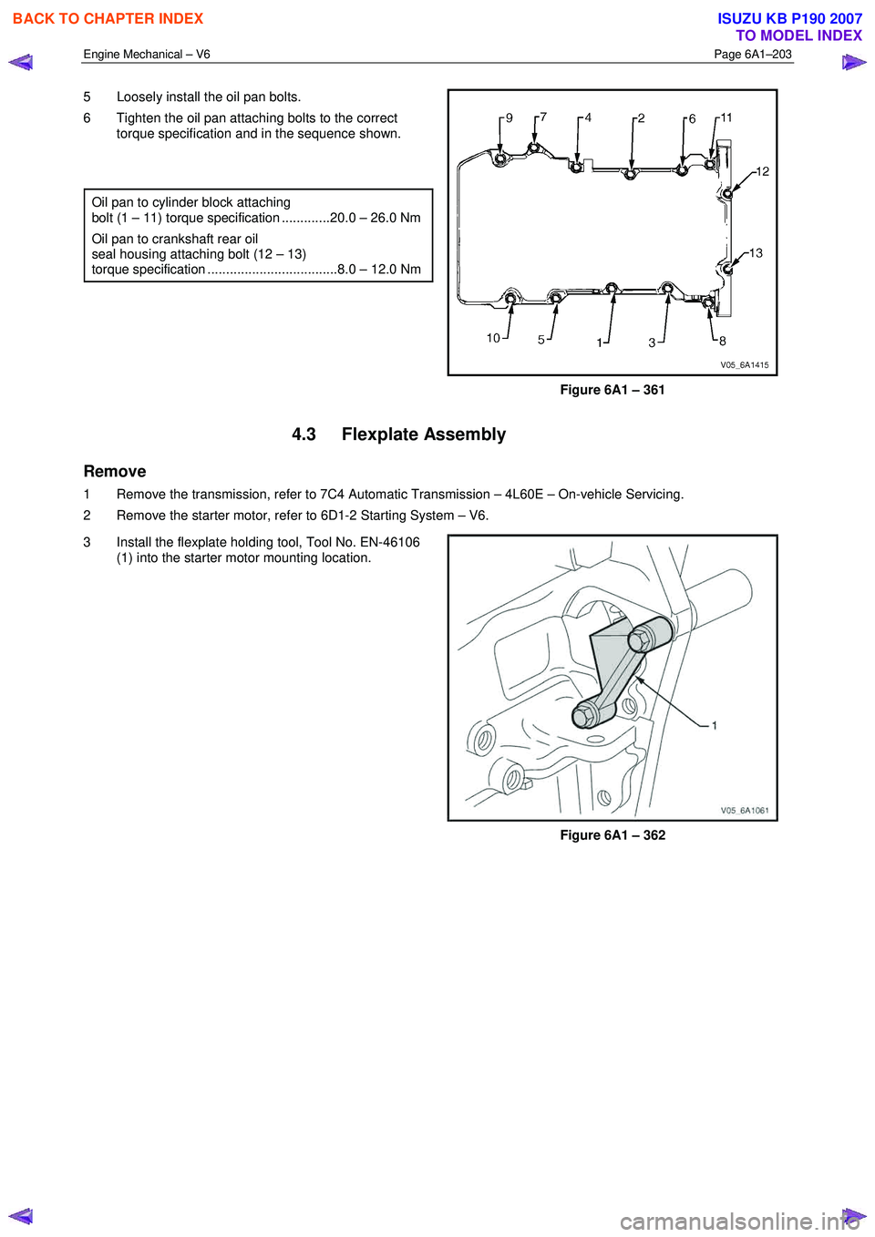
5 Loosely install the oil pan bolts.
6 Tighten the oil pan attaching bolts to the correct torque specification and in the sequence shown.
Oil pan to cylinder block attaching
bolt (1 – 11) torque specification .............20.0 – 26.0 Nm
Oil pan to crankshaft rear oil
seal housing attaching bolt (12 – 13)
torque specification ...................................8.0 – 12.0 Nm
Figure 6A1 – 361
4.3 Flexplate Assembly
Remove
1 Remove the transmission, refer to 7C4 Automatic Transmission – 4L60E – On-vehicle Servicing.
2 Remove the starter motor, refer to 6D1-2 Starting System – V6.
3 Install the flexplate holding tool, Tool No. EN-46106 (1) into the starter motor mounting location.
Figure 6A1 – 362
BACK TO CHAPTER INDEX
TO MODEL INDEX
ISUZU KB P190 2007
Page 2683 of 6020
Engine Mechanical – V6 Page 6A1–204
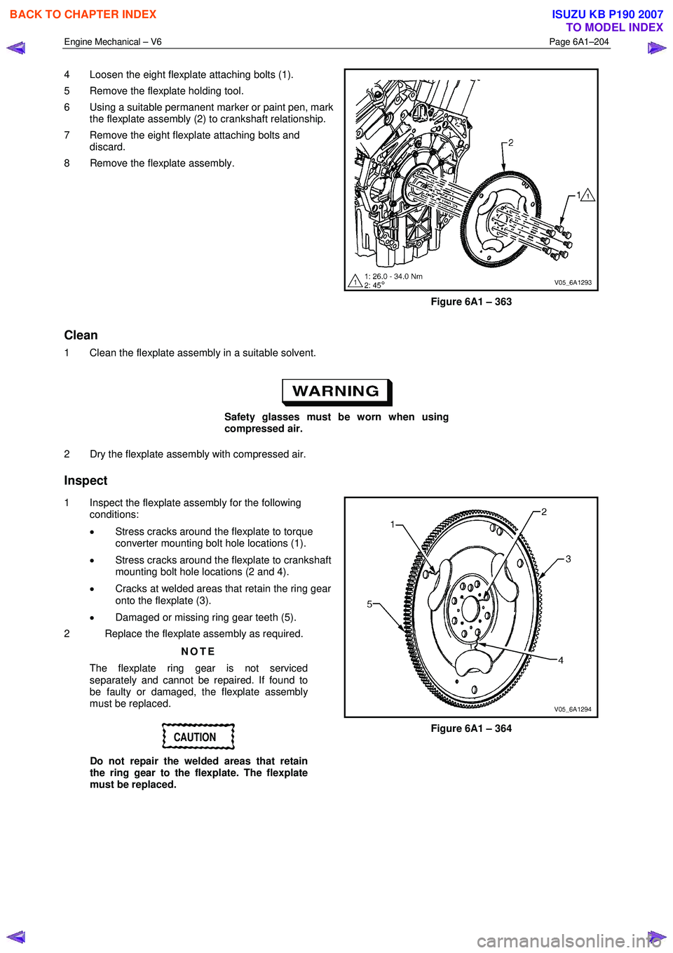
4 Loosen the eight flexplate attaching bolts (1).
5 Remove the flexplate holding tool.
6 Using a suitable permanent marker or paint pen, mark the flexplate assembly (2) to crankshaft relationship.
7 Remove the eight flexplate attaching bolts and discard.
8 Remove the flexplate assembly.
Figure 6A1 – 363
Clean
1 Clean the flexplate assembly in a suitable solvent.
Safety glasses must be worn when using
compressed air.
2 Dry the flexplate assembly with compressed air.
Inspect
1 Inspect the flexplate assembly for the following conditions:
• Stress cracks around the flexplate to torque
converter mounting bolt hole locations (1).
• Stress cracks around the flexplate to crankshaft
mounting bolt hole locations (2 and 4).
• Cracks at welded areas that retain the ring gear
onto the flexplate (3).
• Damaged or missing ring gear teeth (5).
2 Replace the flexplate assembly as required.
NOTE
The flexplate ring gear is not serviced
separately and cannot be repaired. If found to
be faulty or damaged, the flexplate assembly
must be replaced.
CAUTION
Do not repair the welded areas that retain
the ring gear to the flexplate. The flexplate
must be replaced.
Figure 6A1 – 364
BACK TO CHAPTER INDEX
TO MODEL INDEX
ISUZU KB P190 2007
Page 2684 of 6020
Engine Mechanical – V6 Page 6A1–205
Reinstall
NOTE
The bolt holes are unevenly spaced to enable
flexplate fitment in the one position only.
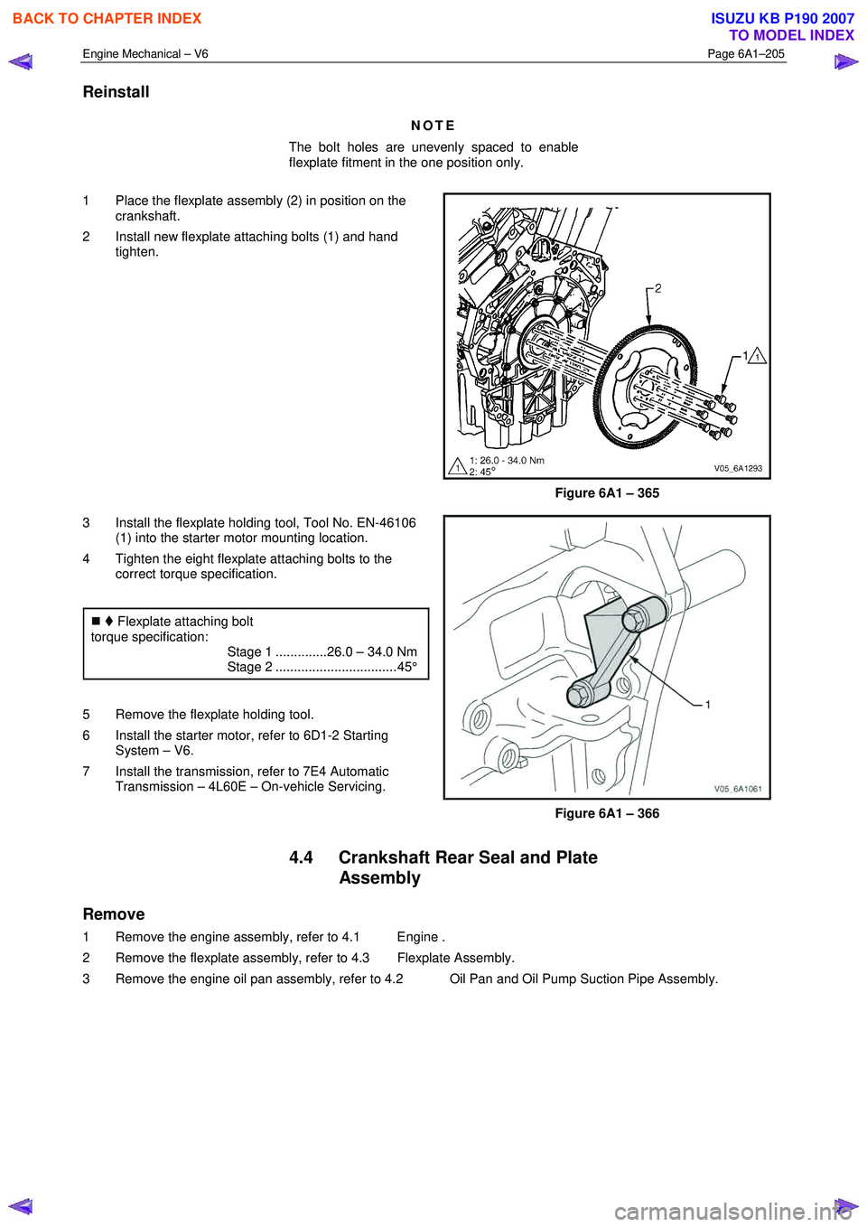
1 Place the flexplate assembly (2) in position on the crankshaft.
2 Install new flexplate attaching bolts (1) and hand tighten.
Figure 6A1 – 365
3 Install the flexplate holding tool, Tool No. EN-46106 (1) into the starter motor mounting location.
4 Tighten the eight flexplate attaching bolts to the correct torque specification.
�„ Flexplate attaching bolt
torque specification:
Stage 1 ..............26.0 – 34.0 Nm
Stage 2 ................................. 45°
5 Remove the flexplate holding tool.
6 Install the starter motor, refer to 6D1-2 Starting System – V6.
7 Install the transmission, refer to 7E4 Automatic Transmission – 4L60E – On-vehicle Servicing.
Figure 6A1 – 366
4.4 Crankshaft Rear Seal and Plate Assembly
Remove
1 Remove the engine assembly, refer to 4.1 Engine .
2 Remove the flexplate assembly, refer to 4.3 Flexplate Assembly.
3 Remove the engine oil pan assembly, refer to 4.2 Oil Pan and Oil Pump Suction Pipe Assembly.
BACK TO CHAPTER INDEX
TO MODEL INDEX
ISUZU KB P190 2007
Page 2701 of 6020
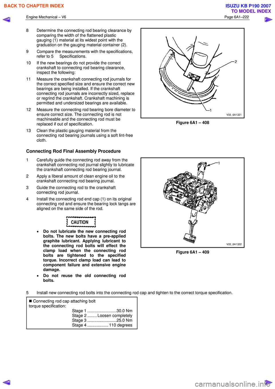
Engine Mechanical – V6 Page 6A1–222
8 Determine the connecting rod bearing clearance by
comparing the width of the flattened plastic
gauging (1) material at its widest point with the
graduation on the gauging material container (2).
9 Compare the measurements with the specifications, refer to 5 Specifications.
10 If the new bearings do not provide the correct crankshaft to connecting rod bearing clearance,
inspect the following:
11 Measure the crankshaft connecting rod journals for the correct specified size and ensure the correct new
bearings are being installed. If the crankshaft
connecting rod journals are incorrectly sized, replace
or regrind the crankshaft. Crankshaft machining is
permitted and undersized bearings are available.
12 Measure the connecting rod bearing bore diameter to ensure correct size. The connecting rod is not
machineable and the connecting rod must be
replaced if out of specification.
13 Clean the plastic gauging material from the connecting rod bearing journals using a soft lint-free
cloth.
Figure 6A1 – 408
Connecting Rod Final Assembly Procedure
1 Carefully guide the connecting rod away from the crankshaft connecting rod journal slightly to lubricate
the crankshaft connecting rod bearing journal.
2 Apply a liberal amount of clean engine oil to the crankshaft connecting rod bearing journal.
3 Guide the connecting rod to the crankshaft connecting rod journal.
4 Install the connecting rod end cap (1) on its original connecting rod and ensure the bearing lock tangs are
aligned on the same side of the rod.
CAUTION
• Do not lubricate the new connecting rod
bolts. The new bolts have a pre-applied
graphite lubricant. Applying lubricant to
the connecting rod bolts will effect the
clamp load when the connecting rod
bolts are tightened to the specified
torque. Incorrect clamp load can lead to
component failure and extensive engine
damage.
• Do not reuse the old connecting rod
bolts.
Figure 6A1 – 409
5 Install new connecting rod bolts into the connecting rod cap and tighten to the correct torque specification. �„ Connecting rod cap attaching bolt
torque specification:
Stage 1 .........................30.0 Nm
Stage 2 ........ Loosen completely
Stage 3 .........................25.0 Nm
Stage 4 .................. 110 degrees
BACK TO CHAPTER INDEX
TO MODEL INDEX
ISUZU KB P190 2007
Page 2705 of 6020
Engine Mechanical – V6 Page 6A1–226
Crankshaft and Main Bearing Visual Inspection
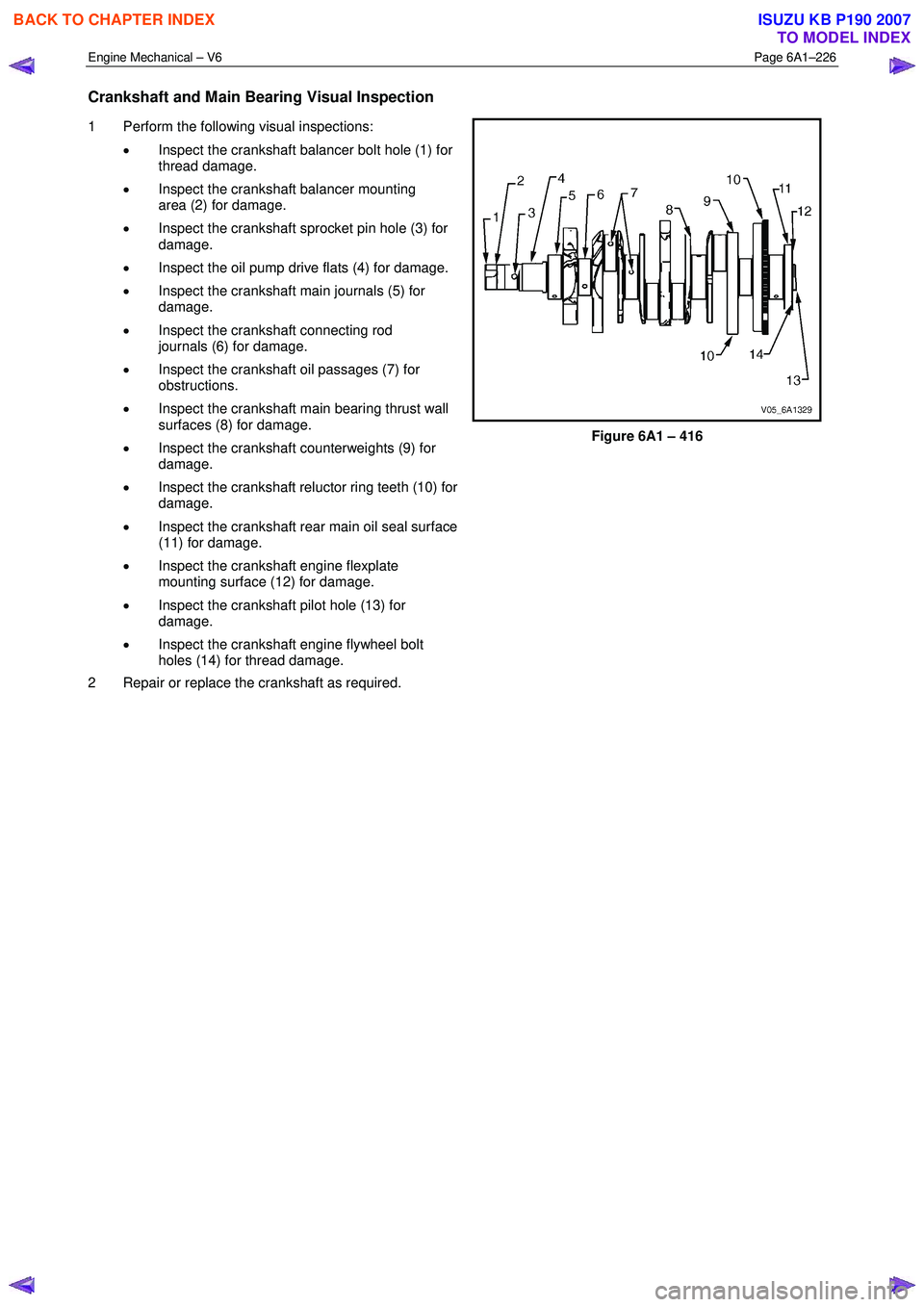
1 Perform the following visual inspections:
• Inspect the crankshaft balancer bolt hole (1) for
thread damage.
• Inspect the crankshaft balancer mounting
area (2) for damage.
• Inspect the crankshaft sprocket pin hole (3) for
damage.
• Inspect the oil pump drive flats (4) for damage.
• Inspect the crankshaft main journals (5) for
damage.
• Inspect the crankshaft connecting rod
journals (6) for damage.
• Inspect the crankshaft oil passages (7) for
obstructions.
• Inspect the crankshaft main bearing thrust wall
surfaces (8) for damage.
• Inspect the crankshaft counterweights (9) for
damage.
• Inspect the crankshaft reluctor ring teeth (10) for
damage.
• Inspect the crankshaft rear main oil seal surface
(11) for damage.
• Inspect the crankshaft engine flexplate
mounting surface (12) for damage.
• Inspect the crankshaft pilot hole (13) for
damage.
• Inspect the crankshaft engine flywheel bolt
holes (14) for thread damage.
2 Repair or replace the crankshaft as required.
Figure 6A1 – 416
BACK TO CHAPTER INDEX
TO MODEL INDEX
ISUZU KB P190 2007
Page 2708 of 6020
Engine Mechanical – V6 Page 6A1–229
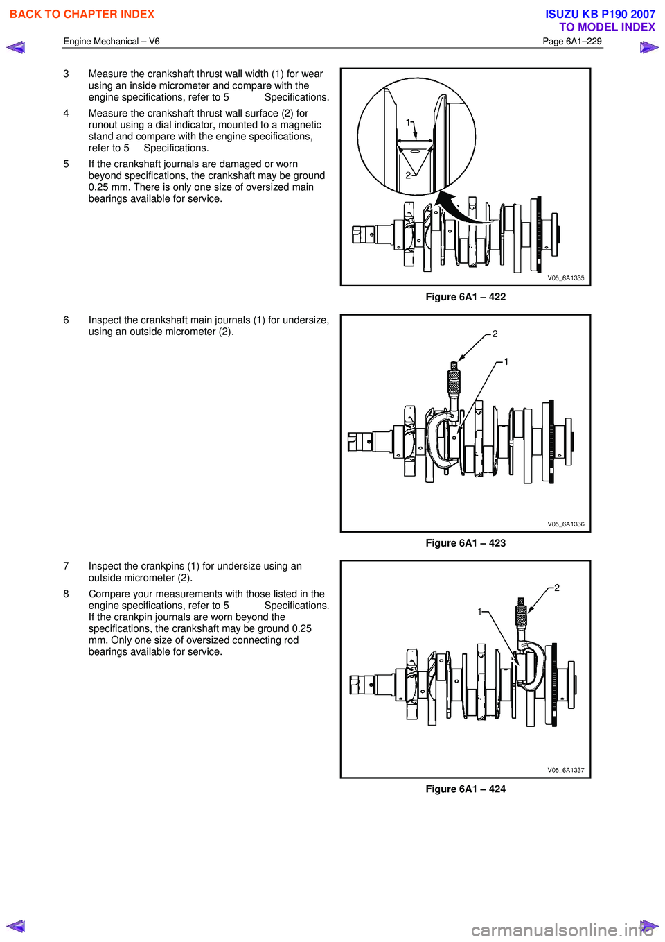
3 Measure the crankshaft thrust wall width (1) for wear
using an inside micrometer and compare with the
engine specifications, refer to 5 Specifications.
4 Measure the crankshaft thrust wall surface (2) for runout using a dial indicator, mounted to a magnetic
stand and compare with the engine specifications,
refer to 5 Specifications.
5 If the crankshaft journals are damaged or worn beyond specifications, the crankshaft may be ground
0.25 mm. There is only one size of oversized main
bearings available for service.
Figure 6A1 – 422
6 Inspect the crankshaft main journals (1) for undersize, using an outside micrometer (2).
Figure 6A1 – 423
7 Inspect the crankpins (1) for undersize using an outside micrometer (2).
8 Compare your measurements with those listed in the engine specifications, refer to 5 Specifications.
If the crankpin journals are worn beyond the
specifications, the crankshaft may be ground 0.25
mm. Only one size of oversized connecting rod
bearings available for service.
Figure 6A1 – 424
BACK TO CHAPTER INDEX
TO MODEL INDEX
ISUZU KB P190 2007
Page 2712 of 6020

Engine Mechanical – V6 Page 6A1–233
Crankshaft Final Installation Procedure
1 If removed, install the crankshaft sprocket drive
pin (1). Lightly tap the pin in place with a small soft
face, bronze/plastic, hammer until it bottoms in the
hole.
Figure 6A1 – 432
CAUTION
Ensure the crankshaft position sensor has
been removed from the cylinder block prior
to loading the crankshaft, as damage to the
sensor may occur.
2
Apply a liberal amount of clean engine oil to the upper
and lower bearing surfaces.
3 Gently lower the crankshaft (1) into position in the cylinder block (2).
Figure 6A1 – 433
4 Install the crankshaft main bearing caps.
5 Loosely install the original inner main cap bolts (1).
CAUTION
The outer crankshaft bearing cap bolts (2)
are yield tightened during assembly and
must be replaced prior to reassembly. Outer
crankshaft bearing cap bolts that are not
replaced will not torque to the correct clamp
load and can lead to serious engine damage.
6 Loosely install the new outer main bearing cap bolts (2).
7 Gently tap the crankshaft main bearing caps with a soft-faced hammer to help seat the caps.
Figure 6A1 – 434
BACK TO CHAPTER INDEX
TO MODEL INDEX
ISUZU KB P190 2007
Page 2718 of 6020
Engine Mechanical – V6 Page 6A1–239
Inspect
Visual Inspection
NOTE
The following procedure assumes the engine has
been disassembled and cleaned, as described
above.
1 Inspect the crankshaft bearing journals for damage or spun bearings. The crankshaft bearing journals are not repairable and if damage is found, the cylinder block assembly must be replaced.
2 Inspect the primary camshaft chain tensioner mounting surface on the engine block for burrs or any defects that would affect the sealing of the new primary camshaft chain tensioner gasket.
3 Inspect all sealing and mating surfaces for damage, repair or replace the cylinder block assembly if required.
4 Inspect all threaded and through holes for damage or excessive debris.
5 Inspect all bolts for damage, if damaged replace with new bolts only.
6 Inspect the cylinder walls for cracks or damage. The cylinder sleeves are not serviced separately, if the cylinders are damaged the cylinder block assembly must be replaced.
7 Inspect the engine block for cracks. Do not repair any cracks. If cracks are found, the cylinder block assembly must be replaced. Repair any damaged threaded holes, refer to 4.9 Thread Repair Specifications.
Measuring Cylinder Bore Diameter
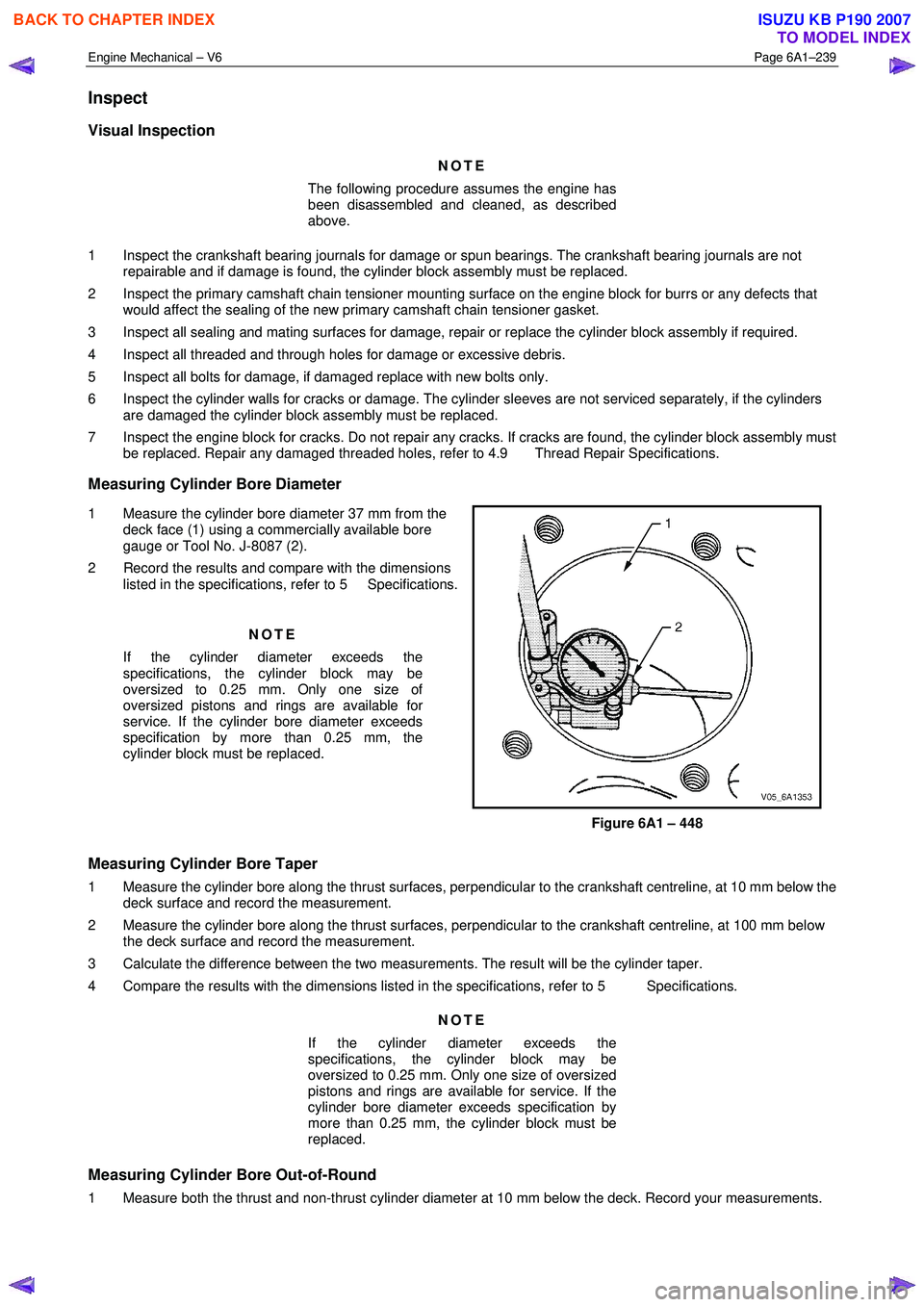
1 Measure the cylinder bore diameter 37 mm from the deck face (1) using a commercially available bore
gauge or Tool No. J-8087 (2).
2 Record the results and compare with the dimensions listed in the specifications, refer to 5 Specifications.
NOTE
If the cylinder diameter exceeds the
specifications, the cylinder block may be
oversized to 0.25 mm. Only one size of
oversized pistons and rings are available for
service. If the cylinder bore diameter exceeds
specification by more than 0.25 mm, the
cylinder block must be replaced.
Figure 6A1 – 448
Measuring Cylinder Bore Taper
1 Measure the cylinder bore along the thrust surfaces, perpendicular to the crankshaft centreline, at 10 mm below the deck surface and record the measurement.
2 Measure the cylinder bore along the thrust surfaces, perpendicular to the crankshaft centreline, at 100 mm below the deck surface and record the measurement.
3 Calculate the difference between the two measurements. The result will be the cylinder taper.
4 Compare the results with the dimensions listed in the specifications, refer to 5 Specifications.
NOTE
If the cylinder diameter exceeds the
specifications, the cylinder block may be
oversized to 0.25 mm. Only one size of oversized
pistons and rings are available for service. If the
cylinder bore diameter exceeds specification by
more than 0.25 mm, the cylinder block must be
replaced.
Measuring Cylinder Bore Out-of-Round
1 Measure both the thrust and non-thrust cylinder diameter at 10 mm below the deck. Record your measurements.
BACK TO CHAPTER INDEX
TO MODEL INDEX
ISUZU KB P190 2007