engine mount ISUZU KB P190 2007 Workshop Repair Manual
[x] Cancel search | Manufacturer: ISUZU, Model Year: 2007, Model line: KB P190, Model: ISUZU KB P190 2007Pages: 6020, PDF Size: 70.23 MB
Page 2635 of 6020
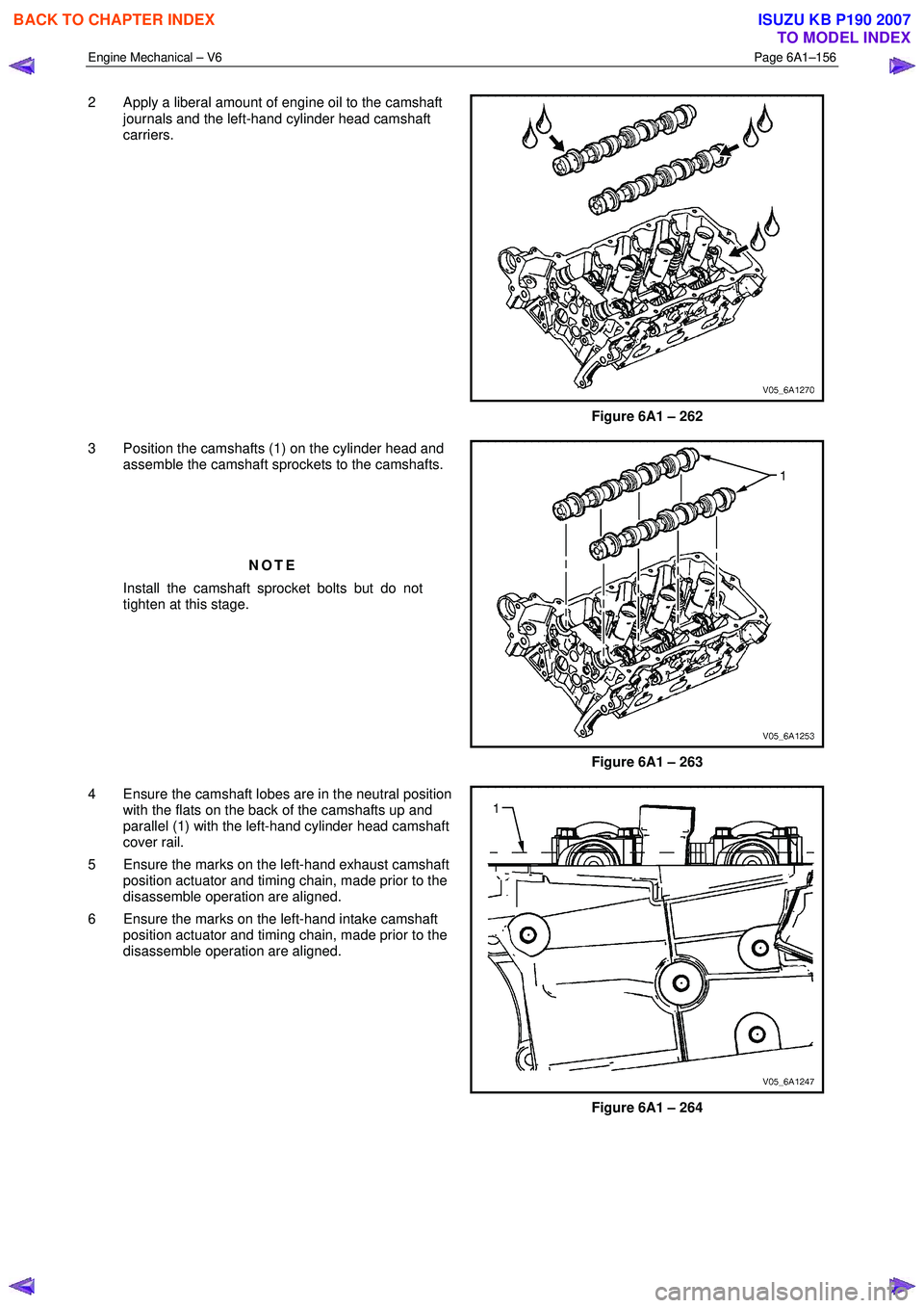
Engine Mechanical – V6 Page 6A1–156
2 Apply a liberal amount of engine oil to the camshaft
journals and the left-hand cylinder head camshaft
carriers.
Figure 6A1 – 262
3 Position the camshafts (1) on the cylinder head and assemble the camshaft sprockets to the camshafts.
NOTE
Install the camshaft sprocket bolts but do not
tighten at this stage.
Figure 6A1 – 263
4 Ensure the camshaft lobes are in the neutral position with the flats on the back of the camshafts up and
parallel (1) with the left-hand cylinder head camshaft
cover rail.
5 Ensure the marks on the left-hand exhaust camshaft position actuator and timing chain, made prior to the
disassemble operation are aligned.
6 Ensure the marks on the left-hand intake camshaft position actuator and timing chain, made prior to the
disassemble operation are aligned.
Figure 6A1 – 264
BACK TO CHAPTER INDEX
TO MODEL INDEX
ISUZU KB P190 2007
Page 2636 of 6020
Engine Mechanical – V6 Page 6A1–157
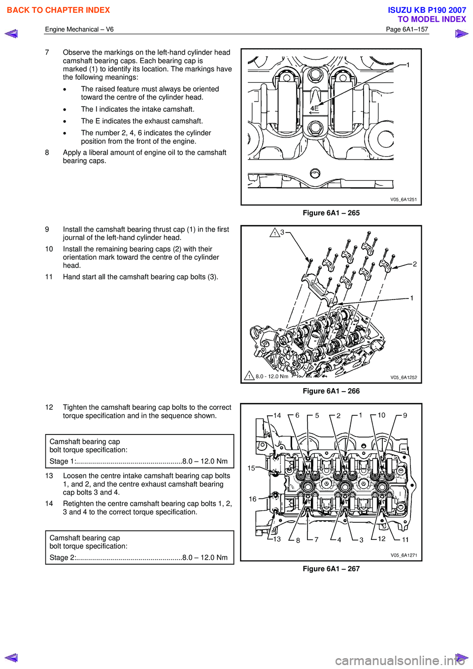
7 Observe the markings on the left-hand cylinder head
camshaft bearing caps. Each bearing cap is
marked (1) to identify its location. The markings have
the following meanings:
• The raised feature must always be oriented
toward the centre of the cylinder head.
• The I indicates the intake camshaft.
• The E indicates the exhaust camshaft.
• The number 2, 4, 6 indicates the cylinder
position from the front of the engine.
8 Apply a liberal amount of engine oil to the camshaft bearing caps.
Figure 6A1 – 265
9 Install the camshaft bearing thrust cap (1) in the first journal of the left-hand cylinder head.
10 Install the remaining bearing caps (2) with their orientation mark toward the centre of the cylinder
head.
11 Hand start all the camshaft bearing cap bolts (3).
Figure 6A1 – 266
12 Tighten the camshaft bearing cap bolts to the correct torque specification and in the sequence shown.
Camshaft bearing cap
bolt torque specification:
Stage 1:.....................................................8.0 – 12.0 Nm
13 Loosen the centre intake camshaft bearing cap bolts 1, and 2, and the centre exhaust camshaft bearing
cap bolts 3 and 4.
14 Retighten the centre camshaft bearing cap bolts 1, 2, 3 and 4 to the correct torque specification.
Camshaft bearing cap
bolt torque specification:
Stage 2:.....................................................8.0 – 12.0 Nm
Figure 6A1 – 267
BACK TO CHAPTER INDEX
TO MODEL INDEX
ISUZU KB P190 2007
Page 2638 of 6020

Engine Mechanical – V6 Page 6A1–159
Reinstall
1 Apply a liberal amount of commercially available
camshaft / lifter prelube or equivalent to the pivot
pocket (1), roller (2) and valve slot (3) areas of the
camshaft followers.
Figure 6A1 – 270
2 Place the rocker arm in position on the valve tip and stationary hydraulic lash adjuster (SHLA). The
rounded head end of the arm seats on the SHLA
while the flat end seats on the valve tip.
CAUTION
• The rocker arm (1) must be positioned
squarely on the valve tip so the full width
of the roller will completely contact the
camshaft lobe.
• If the rocker arms are being reused, they
must be reinstalled in their original
location.
3 Clean the camshaft journals and carriers with a clean, lint-free cloth.
4 Reinstall the camshafts, refer to 3.19 Camshaft.
Figure 6A1 – 271
BACK TO CHAPTER INDEX
TO MODEL INDEX
ISUZU KB P190 2007
Page 2640 of 6020
Engine Mechanical – V6 Page 6A1–161
Reinstall
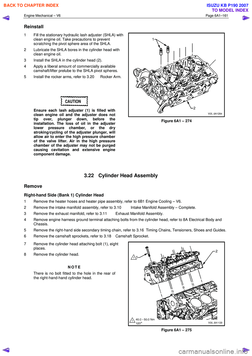
1 Fill the stationary hydraulic lash adjuster (SHLA) with
clean engine oil. Take precautions to prevent
scratching the pivot sphere area of the SHLA.
2 Lubricate the SHLA bores in the cylinder head with clean engine oil.
3 Install the SHLA in the cylinder head (2).
4 Apply a liberal amount of commercially available camshaft/lifter prelube to the SHLA pivot spheres.
5 Install the rocker arms, refer to 3.20 Rocker Arm.
CAUTION
Ensure each lash adjuster (1) is filled with
clean engine oil and the adjuster does not
tip over, plunger down, before the
installation. The loss of oil in the adjuster
lower pressure chamber, or the dry
stroking/cycling of the adjuster plunger, will
allow air to enter the high pressure chamber
of the valve lifter. Air in the high pressure
chamber of the adjuster may not be purged
causing cavitation and extensive engine
component damage.
Figure 6A1 – 274
3.22 Cylinder Head Assembly
Remove
Right-hand Side (Bank 1) Cylinder Head
1 Remove the heater hoses and heater pipe assembly, refer to 6B1 Engine Cooling – V6.
2 Remove the intake manifold assembly, refer to 3.10 Intake Manifold Assembly – Complete.
3 Remove the exhaust manifold, refer to 3.11 Exhaust Manifold Assembly.
4 Remove engine harness ground terminal attaching bolts from the cylinder head, refer to 8A Electrical Body and Chassis.
5 Remove the right-hand side secondary timing chain, refer to 3.16 Timing Chains, Tensioners, Shoes and Guides.
6 Remove the camshaft sprockets, refer to 3.18 Camshaft Sprocket.
7 Remove the cylinder head attaching bolt (1), eight places.
8 Remove the cylinder head.
NOTE
There is no bolt fitted to the hole in the rear of
the right-hand-hand cylinder head.
Figure 6A1 – 275
BACK TO CHAPTER INDEX
TO MODEL INDEX
ISUZU KB P190 2007
Page 2641 of 6020
Engine Mechanical – V6 Page 6A1–162
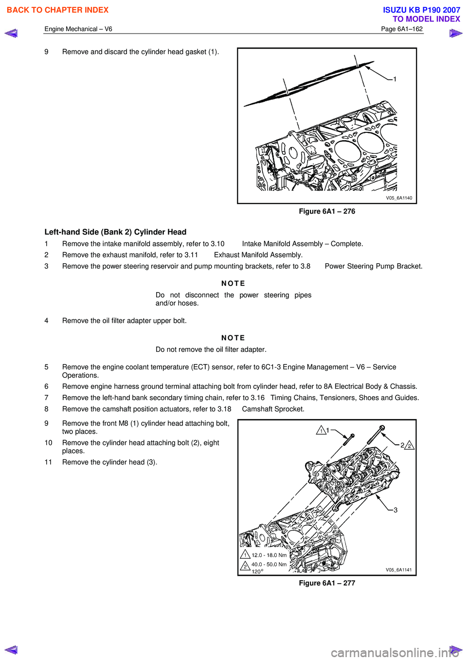
9 Remove and discard the cylinder head gasket (1).
Figure 6A1 – 276
Left-hand Side (Bank 2) Cylinder Head
1 Remove the intake manifold assembly, refer to 3.10 Intake Manifold Assembly – Complete.
2 Remove the exhaust manifold, refer to 3.11 Exhaust Manifold Assembly.
3 Remove the power steering reservoir and pump mounting brackets, refer to 3.8 Power Steering Pump Bracket.
NOTE
Do not disconnect the power steering pipes
and/or hoses.
4 Remove the oil filter adapter upper bolt. NOTE
Do not remove the oil filter adapter.
5 Remove the engine coolant temperature (ECT) sensor, refer to 6C1-3 Engine Management – V6 – Service Operations.
6 Remove engine harness ground terminal attaching bolt from cylinder head, refer to 8A Electrical Body & Chassis.
7 Remove the left-hand bank secondary timing chain, refer to 3.16 Timing Chains, Tensioners, Shoes and Guides.
8 Remove the camshaft position actuators, refer to 3.18 Camshaft Sprocket.
9 Remove the front M8 (1) cylinder head attaching bolt, two places.
10 Remove the cylinder head attaching bolt (2), eight places.
11 Remove the cylinder head (3).
Figure 6A1 – 277
BACK TO CHAPTER INDEX
TO MODEL INDEX
ISUZU KB P190 2007
Page 2647 of 6020
Engine Mechanical – V6 Page 6A1–168
2 Inspect the cylinder head camshaft bearing surfaces for any imperfections or scratches that could inhibit correct
camshaft clearances. Repair minor imperfections or scratches.
3 Install the camshafts in the cylinder head.
4 Install the camshaft bearing caps.
5 Install the camshaft cap bolts and tighten to the correct torque specification.
Camshaft bearing cap attaching bolt........8.0 – 12.0 Nm.
6 Ensure the camshafts spin freely in the cylinder head. If the camshaft does not run freely, replace the cylinder head.
Deck Flatness Inspection
1 Ensure the cylinder head decks are clean and free of gasket material.
2 Inspect the surface for any imperfections or scratches that could inhibit correct cylinder head gasket sealing.
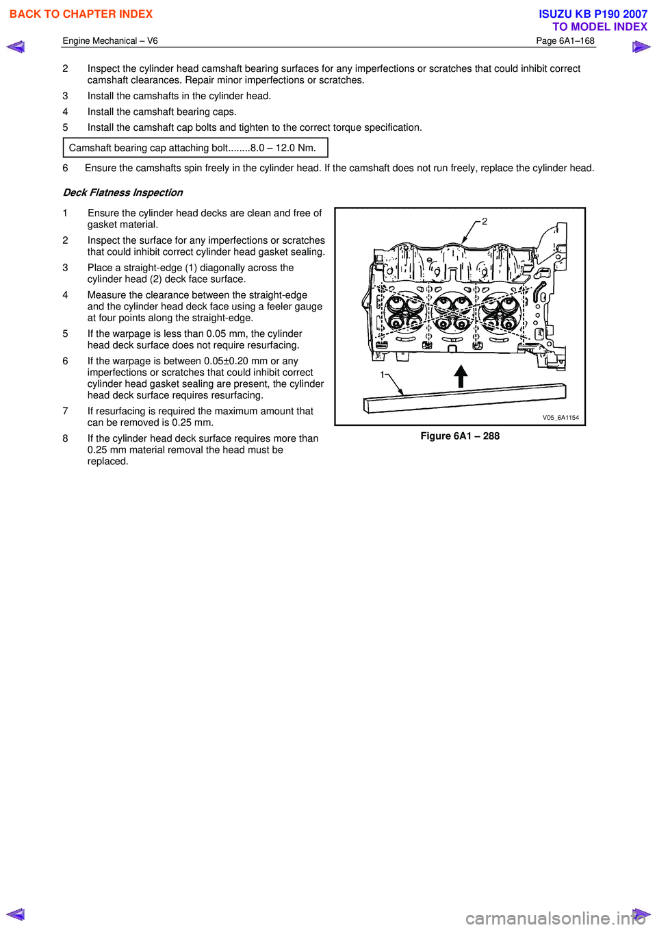
3 Place a straight-edge (1) diagonally across the cylinder head (2) deck face surface.
4 Measure the clearance between the straight-edge and the cylinder head deck face using a feeler gauge
at four points along the straight-edge.
5 If the warpage is less than 0.05 mm, the cylinder head deck surface does not require resurfacing.
6 If the warpage is between 0.05±0.20 mm or any imperfections or scratches that could inhibit correct
cylinder head gasket sealing are present, the cylinder
head deck surface requires resurfacing.
7 If resurfacing is required the maximum amount that can be removed is 0.25 mm.
8 If the cylinder head deck surface requires more than 0.25 mm material removal the head must be
replaced.
Figure 6A1 – 288
BACK TO CHAPTER INDEX
TO MODEL INDEX
ISUZU KB P190 2007
Page 2650 of 6020
Engine Mechanical – V6 Page 6A1–171
Valve Seat Width Measurement Procedure
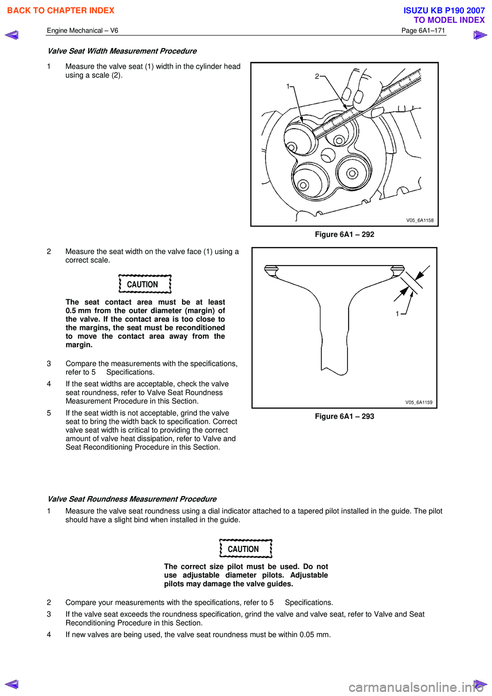
1 Measure the valve seat (1) width in the cylinder head
using a scale (2).
Figure 6A1 – 292
2 Measure the seat width on the valve face (1) using a correct scale.
CAUTION
The seat contact area must be at least
0.5 mm from the outer diameter (margin) of
the valve. If the contact area is too close to
the margins, the seat must be reconditioned
to move the contact area away from the
margin.
3 Compare the measurements with the specifications, refer to 5 Specifications.
4 If the seat widths are acceptable, check the valve seat roundness, refer to Valve Seat Roundness
Measurement Procedure in this Section.
5 If the seat width is not acceptable, grind the valve seat to bring the width back to specification. Correct
valve seat width is critical to providing the correct
amount of valve heat dissipation, refer to Valve and
Seat Reconditioning Procedure in this Section.
Figure 6A1 – 293
Valve Seat Roundness Measurement Procedure
1 Measure the valve seat roundness using a dial indicator attached to a tapered pilot installed in the guide. The pilot should have a slight bind when installed in the guide.
CAUTION
The correct size pilot must be used. Do not
use adjustable diameter pilots. Adjustable
pilots may damage the valve guides.
2 Compare your measurements with the specifications, refer to 5 Specifications.
3 If the valve seat exceeds the roundness specification, grind the valve and valve seat, refer to Valve and Seat Reconditioning Procedure in this Section.
4 If new valves are being used, the valve seat roundness must be within 0.05 mm.
BACK TO CHAPTER INDEX
TO MODEL INDEX
ISUZU KB P190 2007
Page 2657 of 6020
Engine Mechanical – V6 Page 6A1–178
3 Ensure the deck face is clean and the cylinder head
locating pins are securely mounted in the cylinder
block deck face.
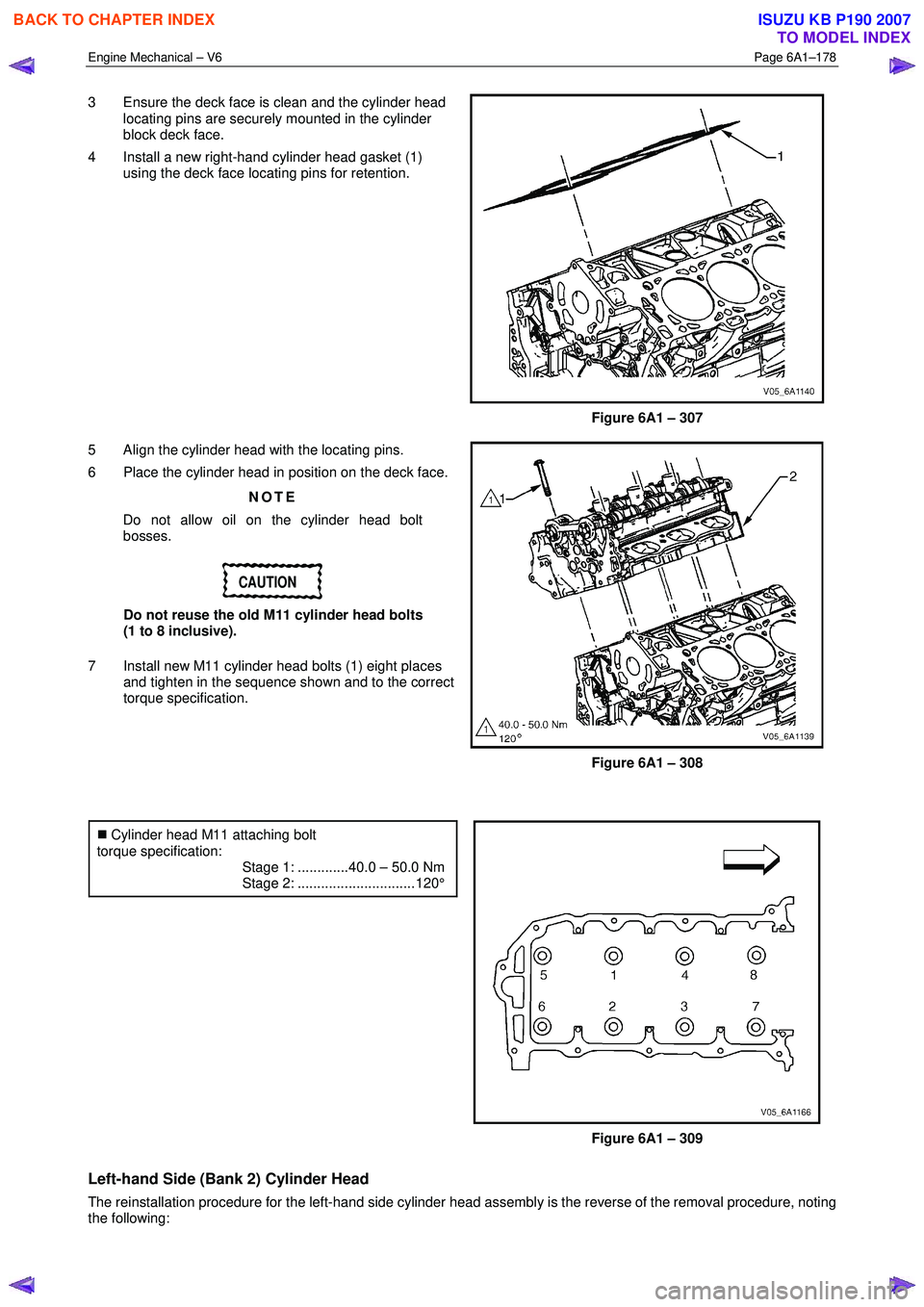
4 Install a new right-hand cylinder head gasket (1) using the deck face locating pins for retention.
Figure 6A1 – 307
5 Align the cylinder head with the locating pins.
6 Place the cylinder head in position on the deck face.
NOTE
Do not allow oil on the cylinder head bolt
bosses.
CAUTION
Do not reuse the old M11 cylinder head bolts
(1 to 8 inclusive).
7 Install new M11 cylinder head bolts (1) eight places and tighten in the sequence shown and to the correct
torque specification.
Figure 6A1 – 308
�„ Cylinder head M11 attaching bolt
torque specification:
Stage 1: .............40.0 – 50.0 Nm
Stage 2: .............................. 120°
Figure 6A1 – 309
Left-hand Side (Bank 2) Cylinder Head
The reinstallation procedure for the left-hand side cylinder head assembly is the reverse of the removal procedure, noting
the following:
BACK TO CHAPTER INDEX
TO MODEL INDEX
ISUZU KB P190 2007
Page 2658 of 6020
Engine Mechanical – V6 Page 6A1–179
1 Ensure all fasteners are tightened to the correct torque specification.
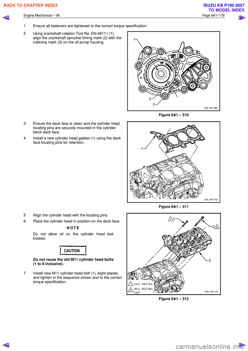
2 Using crankshaft rotation Tool No. EN-46111 (1), align the crankshaft sprocket timing mark (2) with the
indexing mark (3) on the oil pump housing.
Figure 6A1 – 310
3 Ensure the deck face is clean and the cylinder head locating pins are securely mounted in the cylinder
block deck face.
4 Install a new cylinder head gasket (1) using the deck face locating pins for retention.
Figure 6A1 – 311
5 Align the cylinder head with the locating pins.
6 Place the cylinder head in position on the deck face.
NOTE
Do not allow oil on the cylinder head bolt
bosses.
CAUTION
Do not reuse the old M11 cylinder head bolts
(1 to 8 inclusive).
7 Install new M11 cylinder head bolt (1), eight places, and tighten in the sequence shown and to the correct
torque specification.
Figure 6A1 – 312
BACK TO CHAPTER INDEX
TO MODEL INDEX
ISUZU KB P190 2007
Page 2660 of 6020
Engine Mechanical – V6 Page 6A1–181
3.23 Engine Mounts and Brackets
Remove
1 Remove the exhaust manifold assembly from the side of the engine where the engine mount is to be removed,
refer to 3.11 Exhaust Manifold Assembly.
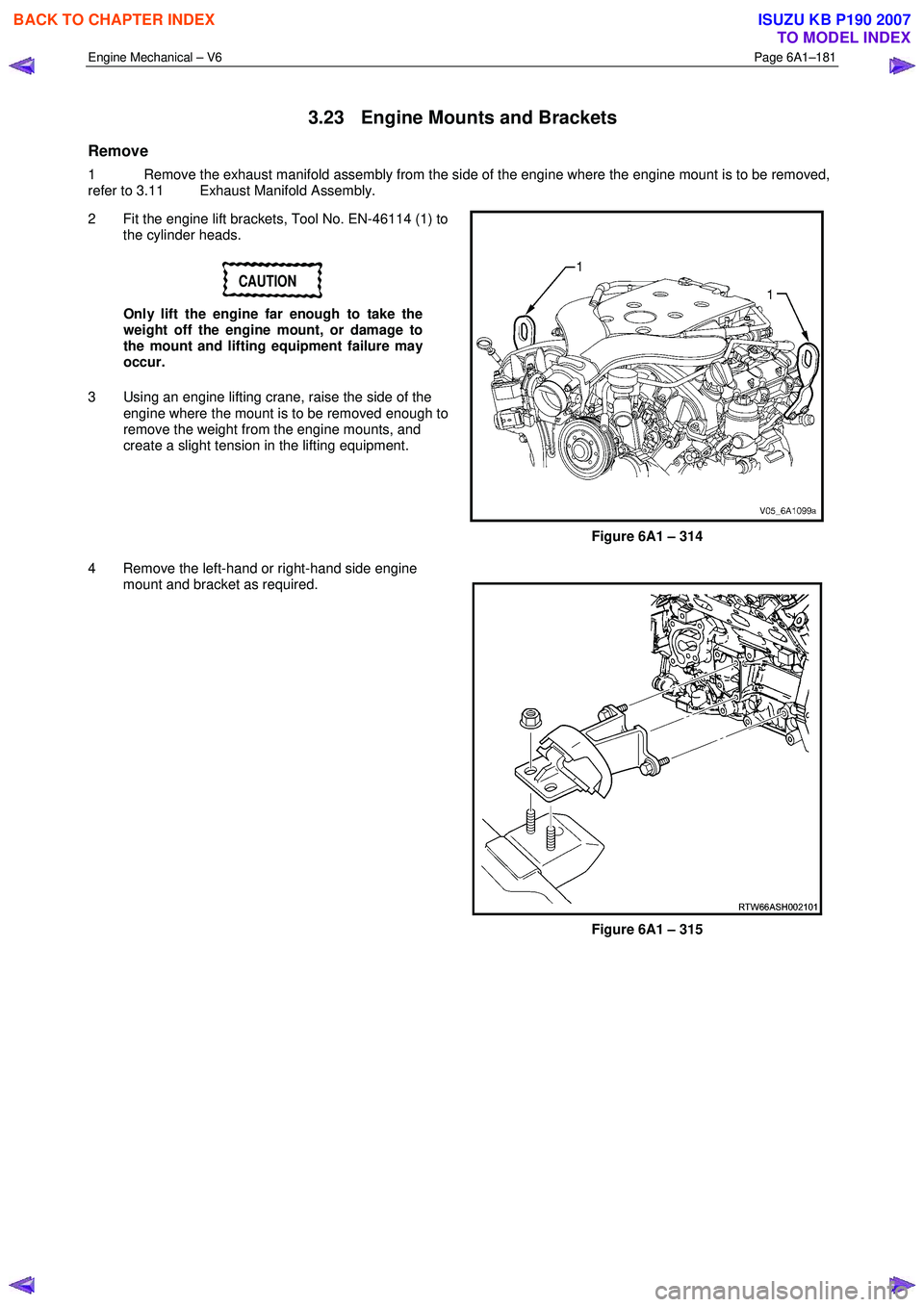
2 Fit the engine lift brackets, Tool No. EN-46114 (1) to the cylinder heads.
CAUTION
Only lift the engine far enough to take the
weight off the engine mount, or damage to
the mount and lifting equipment failure may
occur.
3 Using an engine lifting crane, raise the side of the engine where the mount is to be removed enough to
remove the weight from the engine mounts, and
create a slight tension in the lifting equipment.
Figure 6A1 – 314
4 Remove the left-hand or right-hand side engine mount and bracket as required.
Figure 6A1 – 315
BACK TO CHAPTER INDEX
TO MODEL INDEX
ISUZU KB P190 2007