relay ISUZU KB P190 2007 Workshop Repair Manual
[x] Cancel search | Manufacturer: ISUZU, Model Year: 2007, Model line: KB P190, Model: ISUZU KB P190 2007Pages: 6020, PDF Size: 70.23 MB
Page 3436 of 6020
Engine Management – V6 – Diagnostics Page 6C1-2–158
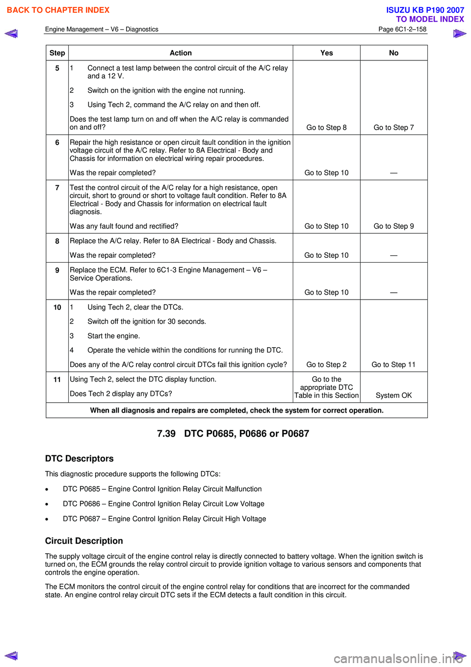
Step Action Yes
No
5 1 Connect a test lamp between the control circuit of the A/C relay
and a 12 V.
2 Switch on the ignition with the engine not running.
3 Using Tech 2, command the A/C relay on and then off.
Does the test lamp turn on and off when the A/C relay is commanded
on and off? Go to Step 8 Go to Step 7
6 Repair the high resistance or open circuit fault condition in the ignition
voltage circuit of the A/C relay. Refer to 8A Electrical - Body and
Chassis for information on electrical wiring repair procedures.
W as the repair completed? Go to Step 10 —
7 Test the control circuit of the A/C relay for a high resistance, open
circuit, short to ground or short to voltage fault condition. Refer to 8A
Electrical - Body and Chassis for information on electrical fault
diagnosis.
W as any fault found and rectified? Go to Step 10 Go to Step 9
8 Replace the A/C relay. Refer to 8A Electrical - Body and Chassis.
W as the repair completed? Go to Step 10 —
9 Replace the ECM. Refer to 6C1-3 Engine Management – V6 –
Service Operations.
W as the repair completed? Go to Step 10 —
10 1 Using Tech 2, clear the DTCs.
2 Switch off the ignition for 30 seconds.
3 Start the engine.
4 Operate the vehicle within the conditions for running the DTC.
Does any of the A/C relay control circuit DTCs fail this ignition cycle? Go to Step 2 Go to Step 11
11 Using Tech 2, select the DTC display function.
Does Tech 2 display any DTCs? Go to the
appropriate DTC
Table in this Section System OK
When all diagnosis and repairs are completed, check the system for correct operation.
7.39 DTC P0685, P0686 or P0687
DTC Descriptors
This diagnostic procedure supports the following DTCs:
• DTC P0685 – Engine Control Ignition Relay Circuit Malfunction
• DTC P0686 – Engine Control Ignition Relay Circuit Low Voltage
• DTC P0687 – Engine Control Ignition Relay Circuit High Voltage
Circuit Description
The supply voltage circuit of the engine control relay is directly connected to battery voltage. W hen the ignition switch is
turned on, the ECM grounds the relay control circuit to provide ignition voltage to various sensors and components that
controls the engine operation.
The ECM monitors the control circuit of the engine control relay for conditions that are incorrect for the commanded
state. An engine control relay circuit DTC sets if the ECM detects a fault condition in this circuit.
BACK TO CHAPTER INDEX
TO MODEL INDEX
ISUZU KB P190 2007
Page 3437 of 6020
Engine Management – V6 – Diagnostics Page 6C1-2–159
Conditions for Running the DTC
DTCs P0685, P0686 and P0687 run continuously once the following conditions are met:
• The ignition is switched on
• The ignition voltage is 10.0 – 16.0 V.
Conditions for Setting the DTC
The ECM detects a condition that is incorrect for the engine control relay commanded state.
Conditions for Clearing the DTC
The engine control relay control circuit DTCs are Type C DTCs. Refer to 1.4 Diagnostic Trouble Codes in this
Section, for action taken when Type C DTCs set and conditions for clearing Type C DTCs.
Additional Information
• For an intermittent fault condition, refer to 5.2 Intermittent Fault Conditions in this Section.
• Since fault condition in a wiring connector may trigger DTCs, always test the connectors related to this diagnostic
procedure for shorted terminals or poor wiring connection before replacing any component. Refer to 8A Electrical -
Body and Chassis for information on electrical fault diagnosis.
• To assist diagnosis, refer to 3 W iring Diagrams and Connector Charts in this Section, for the system wiring
diagram and connector charts.
Test Description
The following number refers to the step number in the diagnostic table:
4 Removal of the ECM Fuse 29 enables the ECM to power down completely prior to the test procedure.
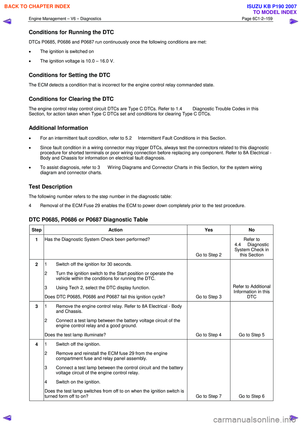
DTC P0685, P0686 or P0687 Diagnostic Table
Step Action Yes No
1 Has the Diagnostic System Check been performed?
Go to Step 2 Refer to
4.4 Diagnostic
System Check in this Section
2 1 Switch off the ignition for 30 seconds.
2 Turn the ignition switch to the Start position or operate the vehicle within the conditions for running the DTC.
3 Using Tech 2, select the DTC display function.
Does DTC P0685, P0686 and P0687 fail this ignition cycle? Go to Step 3 Refer to Additional
Information in this DTC
3 1 Remove the engine control relay. Refer to 8A Electrical - Body
and Chassis.
2 Connect a test lamp between the battery voltage circuit of the engine control relay and a good ground.
Does the test lamp illuminate? Go to Step 4 Go to Step 5
4 1 Switch off the ignition.
2 Remove and reinstall the ECM fuse 29 from the engine compartment fuse and relay panel assembly.
3 Connect a test lamp between the control circuit and the battery voltage circuit of the engine control relay.
4 Switch on the ignition.
Does the test lamp switches from off to on when the ignition switch is
turned form off to on? Go to Step 7 Go to Step 6
BACK TO CHAPTER INDEX
TO MODEL INDEX
ISUZU KB P190 2007
Page 3438 of 6020
Engine Management – V6 – Diagnostics Page 6C1-2–160
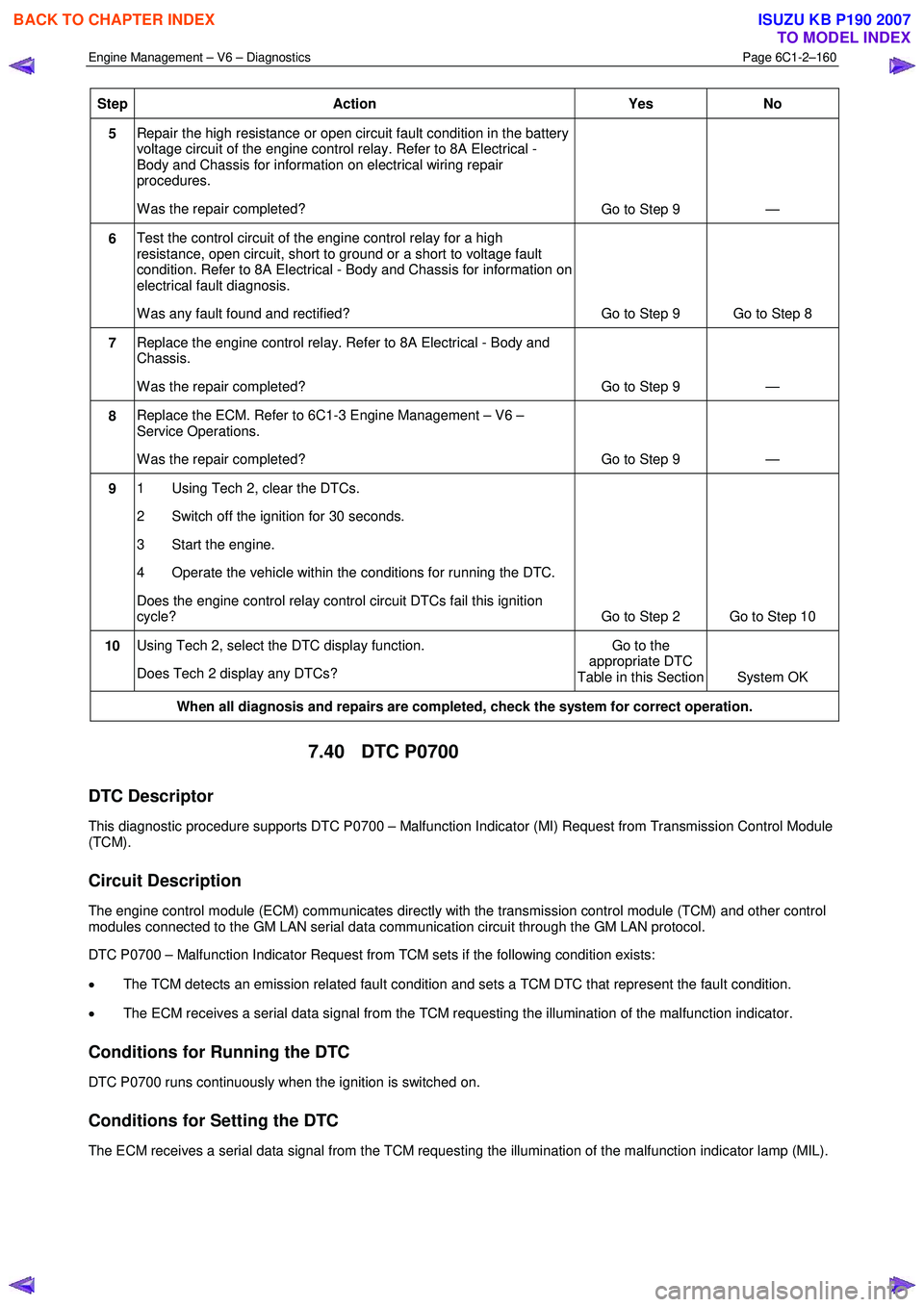
Step Action Yes
No
5 Repair the high resistance or open circuit fault condition in the battery
voltage circuit of the engine control relay. Refer to 8A Electrical -
Body and Chassis for information on electrical wiring repair
procedures.
W as the repair completed? Go to Step 9 —
6 Test the control circuit of the engine control relay for a high
resistance, open circuit, short to ground or a short to voltage fault
condition. Refer to 8A Electrical - Body and Chassis for information on
electrical fault diagnosis.
W as any fault found and rectified? Go to Step 9 Go to Step 8
7 Replace the engine control relay. Refer to 8A Electrical - Body and
Chassis.
W as the repair completed? Go to Step 9 —
8 Replace the ECM. Refer to 6C1-3 Engine Management – V6 –
Service Operations.
W as the repair completed? Go to Step 9 —
9 1 Using Tech 2, clear the DTCs.
2 Switch off the ignition for 30 seconds.
3 Start the engine.
4 Operate the vehicle within the conditions for running the DTC.
Does the engine control relay control circuit DTCs fail this ignition
cycle? Go to Step 2 Go to Step 10
10 Using Tech 2, select the DTC display function.
Does Tech 2 display any DTCs? Go to the
appropriate DTC
Table in this Section System OK
When all diagnosis and repairs are completed, check the system for correct operation.
7.40 DTC P0700
DTC Descriptor
This diagnostic procedure supports DTC P0700 – Malfunction Indicator (MI) Request from Transmission Control Module
(TCM).
Circuit Description
The engine control module (ECM) communicates directly with the transmission control module (TCM) and other control
modules connected to the GM LAN serial data communication circuit through the GM LAN protocol.
DTC P0700 – Malfunction Indicator Request from TCM sets if the following condition exists:
• The TCM detects an emission related fault condition and sets a TCM DTC that represent the fault condition.
• The ECM receives a serial data signal from the TCM requesting the illumination of the malfunction indicator.
Conditions for Running the DTC
DTC P0700 runs continuously when the ignition is switched on.
Conditions for Setting the DTC
The ECM receives a serial data signal from the TCM requesting the illumination of the malfunction indicator lamp (MIL).
BACK TO CHAPTER INDEX
TO MODEL INDEX
ISUZU KB P190 2007
Page 3457 of 6020
Engine Management – V6 – Diagnostics Page 6C1-2–179
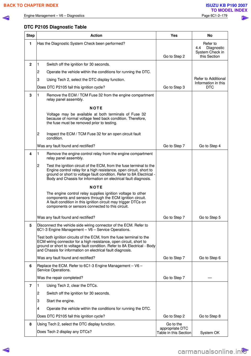
DTC P2105 Diagnostic Table
Step Action Yes No
1 Has the Diagnostic System Check been performed?
Go to Step 2 Refer to
4.4 Diagnostic
System Check in this Section
2 1 Switch off the ignition for 30 seconds.
2 Operate the vehicle within the conditions for running the DTC.
3 Using Tech 2, select the DTC display function.
Does DTC P2105 fail this ignition cycle? Go to Step 3 Refer to Additional
Information in this DTC
3 1 Remove the ECM / TCM Fuse 32 from the engine compartment
relay panel assembly.
NOTE
Voltage may be available at both terminals of Fuse 32
because of normal voltage feed back condition. Therefore,
the fuse must be removed prior to testing.
2 Inspect the ECM / TCM Fuse 32 for an open circuit fault condition.
W as any fault found and rectified? Go to Step 7 Go to Step 4
4 1 Remove the engine control relay from the engine compartment
relay panel assembly.
2 Test the ignition circuit of the ECM, from the fuse terminal to the Engine control relay for a high resistance, open circuit, short to
ground or short to voltage fault condition. Refer to 8A Electrical -
Body and Chassis for information on electrical fault diagnosis.
NOTE
The engine control relay supplies ignition voltage to other
components and sensors through the ECM ignition circuit.
A fault condition in this ignition circuit may trigger DTCs on
components or sensors connected to this circuit.
W as any fault found and rectified? Go to Step 7 Go to Step 5
5 Disconnect the vehicle side wiring connector of the ECM. Refer to
6C1-3 Engine Management – V6 – Service Operations.
Test both ignition circuits of the ECM, from the fuse terminal to the
ECM wiring connector for a high resistance, open circuit, short to
ground or short to voltage fault condition. Refer to 8A Electrical - Body
and Chassis for information on electrical fault diagnosis.
W as any fault found and rectified? Go to Step 7 Go to Step 6
6 Replace the ECM. Refer to 6C1-3 Engine Management – V6 –
Service Operations.
W as the repair completed? Go to Step 7 —
7 1 Using Tech 2, clear the DTCs.
2 Switch off the ignition for 30 seconds.
3 Start the engine.
4 Operate the vehicle within the conditions for running the DTC.
Does DTC P2105 fail this ignition cycle? Go to Step 2 Go to Step 8
8 Using Tech 2, select the DTC display function.
Does Tech 2 display any DTCs? Go to the
appropriate DTC
Table in this Section System OK
BACK TO CHAPTER INDEX
TO MODEL INDEX
ISUZU KB P190 2007
Page 3461 of 6020
Engine Management – V6 – Diagnostics Page 6C1-2–183
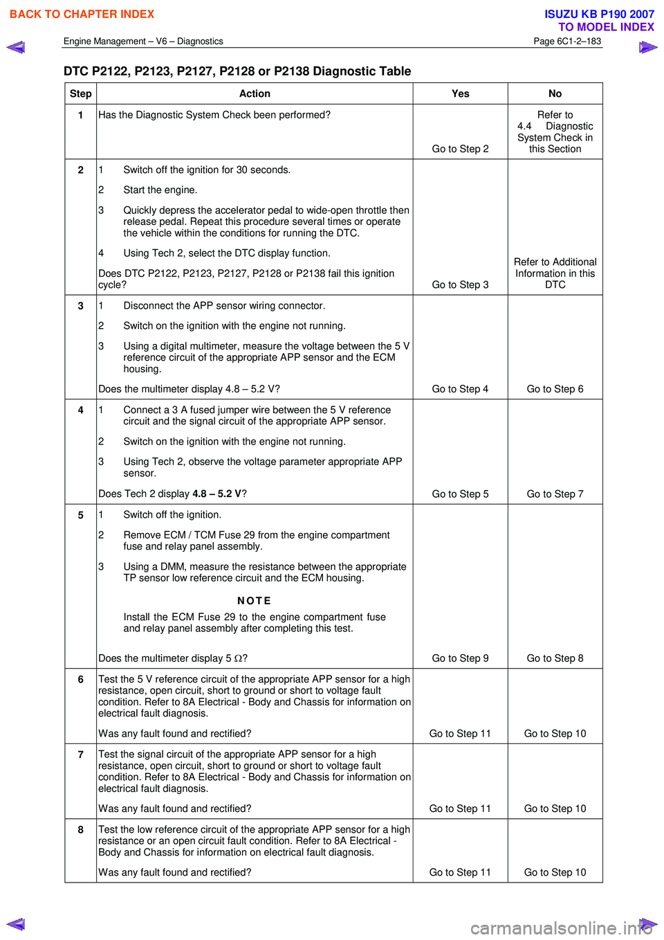
DTC P2122, P2123, P2127, P2128 or P2138 Diagnostic Table
Step Action Yes No
1 Has the Diagnostic System Check been performed?
Go to Step 2 Refer to
4.4 Diagnostic
System Check in this Section
2 1 Switch off the ignition for 30 seconds.
2 Start the engine.
3 Quickly depress the accelerator pedal to wide-open throttle then release pedal. Repeat this procedure several times or operate
the vehicle within the conditions for running the DTC.
4 Using Tech 2, select the DTC display function.
Does DTC P2122, P2123, P2127, P2128 or P2138 fail this ignition
cycle? Go to Step 3 Refer to Additional
Information in this DTC
3 1 Disconnect the APP sensor wiring connector.
2 Switch on the ignition with the engine not running.
3 Using a digital multimeter, measure the voltage between the 5 V reference circuit of the appropriate APP sensor and the ECM
housing.
Does the multimeter display 4.8 – 5.2 V? Go to Step 4 Go to Step 6
4 1 Connect a 3 A fused jumper wire between the 5 V reference
circuit and the signal circuit of the appropriate APP sensor.
2 Switch on the ignition with the engine not running.
3 Using Tech 2, observe the voltage parameter appropriate APP sensor.
Does Tech 2 display 4.8 – 5.2 V ?
Go to Step 5 Go to Step 7
5 1 Switch off the ignition.
2 Remove ECM / TCM Fuse 29 from the engine compartment fuse and relay panel assembly.
3 Using a DMM, measure the resistance between the appropriate TP sensor low reference circuit and the ECM housing.
NOTE
Install the ECM Fuse 29 to the engine compartment fuse
and relay panel assembly after completing this test.
Does the multimeter display 5 Ω? Go to Step 9 Go to Step 8
6 Test the 5 V reference circuit of the appropriate APP sensor for a high
resistance, open circuit, short to ground or short to voltage fault
condition. Refer to 8A Electrical - Body and Chassis for information on
electrical fault diagnosis.
W as any fault found and rectified? Go to Step 11 Go to Step 10
7 Test the signal circuit of the appropriate APP sensor for a high
resistance, open circuit, short to ground or short to voltage fault
condition. Refer to 8A Electrical - Body and Chassis for information on
electrical fault diagnosis.
W as any fault found and rectified? Go to Step 11 Go to Step 10
8 Test the low reference circuit of the appropriate APP sensor for a high
resistance or an open circuit fault condition. Refer to 8A Electrical -
Body and Chassis for information on electrical fault diagnosis.
W as any fault found and rectified? Go to Step 11 Go to Step 10
BACK TO CHAPTER INDEX
TO MODEL INDEX
ISUZU KB P190 2007
Page 3485 of 6020
Engine Management – V6 – Diagnostics Page 6C1-2–207
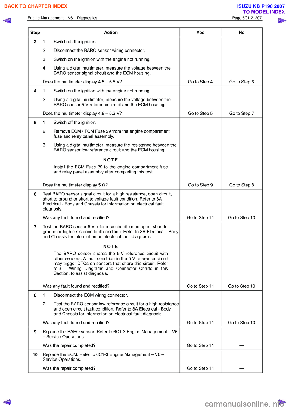
Step Action Yes
No
3 1 Switch off the ignition.
2 Disconnect the BARO sensor wiring connector.
3 Switch on the ignition with the engine not running.
4 Using a digital multimeter, measure the voltage between the BARO sensor signal circuit and the ECM housing.
Does the multimeter display 4.5 – 5.5 V? Go to Step 4 Go to Step 6
4 1 Switch on the ignition with the engine not running.
2 Using a digital multimeter, measure the voltage between the BARO sensor 5 V reference circuit and the ECM housing.
Does the multimeter display 4.8 – 5.2 V? Go to Step 5 Go to Step 7
5 1 Switch off the ignition.
2 Remove ECM / TCM Fuse 29 from the engine compartment fuse and relay panel assembly.
3 Using a digital multimeter, measure the resistance between the BARO sensor low reference circuit and the ECM housing.
NOTE
Install the ECM Fuse 29 to the engine compartment fuse
and relay panel assembly after completing this test.
Does the multimeter display 5 Ω? Go to Step 9 Go to Step 8
6 Test BARO sensor signal circuit for a high resistance, open circuit,
short to ground or short to voltage fault condition. Refer to 8A
Electrical - Body and Chassis for information on electrical fault
diagnosis.
W as any fault found and rectified? Go to Step 11 Go to Step 10
7 Test the BARO sensor 5 V reference circuit for an open, short to
ground or high resistance fault condition. Refer to 8A Electrical - Body
and Chassis for information on electrical fault diagnosis.
NOTE
The BARO sensor shares the 5 V reference circuit with
other sensors. A fault condition in the 5 V reference circuit
may trigger DTCs on sensors that share this circuit. Refer
to 3 W iring Diagrams and Connector Charts in this
Section, to assist diagnosis.
W as any fault found and rectified? Go to Step 11 Go to Step 10
8 1 Disconnect the ECM wiring connector.
2 Test the BARO sensor low reference circuit for a high resistance and open circuit fault condition. Refer to 8A Electrical - Body
and Chassis for information on electrical fault diagnosis.
W as any fault found and rectified? Go to Step 11 Go to Step 10
9 Replace the BARO sensor. Refer to 6C1-3 Engine Management – V6
– Service Operations.
W as the repair completed? Go to Step 11 —
10 Replace the ECM. Refer to 6C1-3 Engine Management – V6 –
Service Operations.
W as the repair completed? Go to Step 11 —
BACK TO CHAPTER INDEX
TO MODEL INDEX
ISUZU KB P190 2007
Page 3486 of 6020
Engine Management – V6 – Diagnostics Page 6C1-2–208
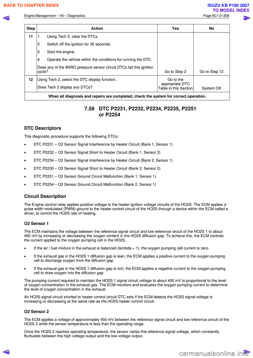
Step Action Yes
No
11 1 Using Tech 2, clear the DTCs.
2 Switch off the ignition for 30 seconds.
3 Start the engine.
4 Operate the vehicle within the conditions for running the DTC.
Does any of the BARO pressure sensor circuit DTCs fail this ignition
cycle? Go to Step 2 Go to Step 12
12 Using Tech 2, select the DTC display function.
Does Tech 2 display any DTCs? Go to the
appropriate DTC
Table in this Section System OK
When all diagnosis and repairs are completed, check the system for correct operation.
7.58 DTC P2231, P2232, P2234, P2235, P2251
or P2254
DTC Descriptors
This diagnostic procedure supports the following DTCs:
• DTC P2231 – O2 Sensor Signal Interference by Heater Circuit (Bank 1, Sensor 1)
• DTC P2232 – O2 Sensor Signal Short to Heater Circuit (Bank 1, Sensor 2)
• DTC P2234 – O2 Sensor Signal Interference by Heater Circuit (Bank 2, Sensor 1)
• DTC P2235 – O2 Sensor Signal Short to Heater Circuit (Bank 2, Sensor 2)
• DTC P2251 – O2 Sensor Ground Circuit Malfunction (Bank 1, Sensor 1)
• DTC P2254 – O2 Sensor Ground Circuit Malfunction (Bank 2, Sensor 1)
Circuit Description
The Engine control relay applies positive voltage to the heater ignition voltage circuits of the HO2S. The ECM applies a
pulse width modulated (PW M) ground to the heater control circuit of the HO2S through a device within the ECM called a
driver, to control the HO2S rate of heating.
O2 Sensor 1
The ECM maintains the voltage between the reference signal circuit and low reference circuit of the HO2S 1 to about
450 mV by increasing or decreasing the oxygen content in the HO2S diffusion gap. To achieve this, the ECM controls
the current applied to the oxygen pumping cell in the HO2S.
• If the air / fuel mixture in the exhaust is balanced (lambda = 1), the oxygen pumping cell current is zero.
• If the exhaust gas in the HO2S 1 diffusion gap is lean, the ECM applies a positive current to the oxygen pumping
cell to discharge oxygen from the diffusion gap.
• If the exhaust gas in the HO2S 1 diffusion gap is rich, the ECM applies a negative current to the oxygen pumping
cell to draw oxygen into the diffusion gap.
The pumping current required to maintain the HO2S 1 signal circuit voltage to about 450 mV is proportional to the level
of oxygen concentration in the exhaust gas. The ECM monitors and evaluates the oxygen pumping current to determine
the level of oxygen concentration in the exhaust.
An HO2S signal circuit shorted to heater control circuit DTC sets if the ECM detects the HO2S signal voltage is
increasing or decreasing at the same rate as the HO2S heater control circuit.
O2 Sensor 2
The ECM applies a voltage of approximately 450 mV between the reference signal circuit and low reference circuit of the
HO2S 2 while the sensor temperature is less than the operating range.
Once the HO2S 2 reaches operating temperature, the sensor varies this reference signal voltage, which constantly
fluctuates between the high voltage output and the low voltage output.
BACK TO CHAPTER INDEX
TO MODEL INDEX
ISUZU KB P190 2007
Page 3489 of 6020
Engine Management – V6 – Diagnostics Page 6C1-2–211
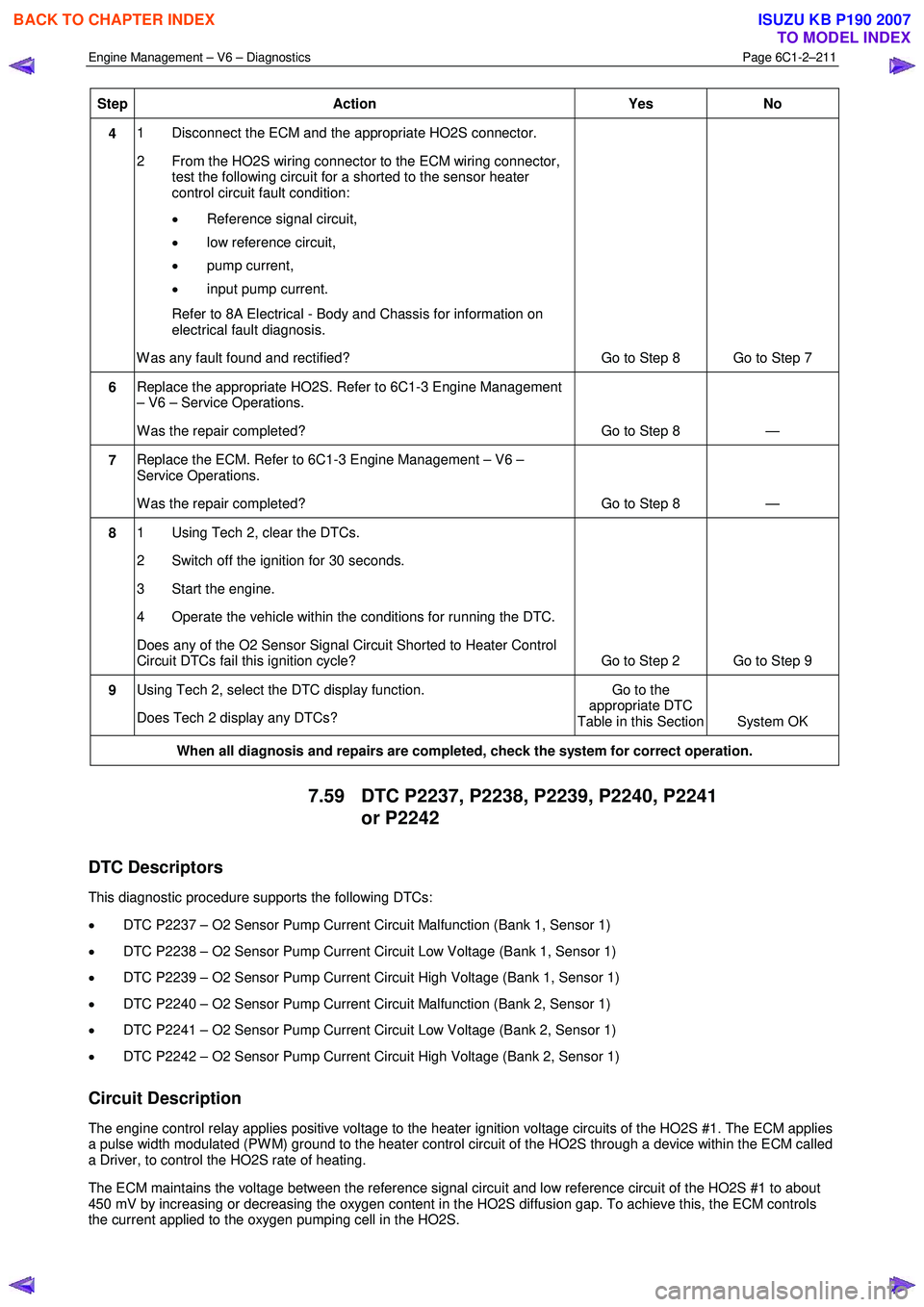
Step Action Yes No
4 1 Disconnect the ECM and the appropriate HO2S connector.
2 From the HO2S wiring connector to the ECM wiring connector, test the following circuit for a shorted to the sensor heater
control circuit fault condition:
• Reference signal circuit,
• low reference circuit,
• pump current,
• input pump current.
Refer to 8A Electrical - Body and Chassis for information on electrical fault diagnosis.
W as any fault found and rectified? Go to Step 8 Go to Step 7
6 Replace the appropriate HO2S. Refer to 6C1-3 Engine Management
– V6 – Service Operations.
W as the repair completed? Go to Step 8 —
7 Replace the ECM. Refer to 6C1-3 Engine Management – V6 –
Service Operations.
W as the repair completed? Go to Step 8 —
8 1 Using Tech 2, clear the DTCs.
2 Switch off the ignition for 30 seconds.
3 Start the engine.
4 Operate the vehicle within the conditions for running the DTC.
Does any of the O2 Sensor Signal Circuit Shorted to Heater Control
Circuit DTCs fail this ignition cycle? Go to Step 2 Go to Step 9
9 Using Tech 2, select the DTC display function.
Does Tech 2 display any DTCs? Go to the
appropriate DTC
Table in this Section System OK
When all diagnosis and repairs are completed, check the system for correct operation.
7.59 DTC P2237, P2238, P2239, P2240, P2241
or P2242
DTC Descriptors
This diagnostic procedure supports the following DTCs:
• DTC P2237 – O2 Sensor Pump Current Circuit Malfunction (Bank 1, Sensor 1)
• DTC P2238 – O2 Sensor Pump Current Circuit Low Voltage (Bank 1, Sensor 1)
• DTC P2239 – O2 Sensor Pump Current Circuit High Voltage (Bank 1, Sensor 1)
• DTC P2240 – O2 Sensor Pump Current Circuit Malfunction (Bank 2, Sensor 1)
• DTC P2241 – O2 Sensor Pump Current Circuit Low Voltage (Bank 2, Sensor 1)
• DTC P2242 – O2 Sensor Pump Current Circuit High Voltage (Bank 2, Sensor 1)
Circuit Description
The engine control relay applies positive voltage to the heater ignition voltage circuits of the HO2S #1. The ECM applies
a pulse width modulated (PW M) ground to the heater control circuit of the HO2S through a device within the ECM called
a Driver, to control the HO2S rate of heating.
The ECM maintains the voltage between the reference signal circuit and low reference circuit of the HO2S #1 to about
450 mV by increasing or decreasing the oxygen content in the HO2S diffusion gap. To achieve this, the ECM controls
the current applied to the oxygen pumping cell in the HO2S.
BACK TO CHAPTER INDEX
TO MODEL INDEX
ISUZU KB P190 2007
Page 3502 of 6020
Engine Management – V6 – Diagnostics Page 6C1-2–224
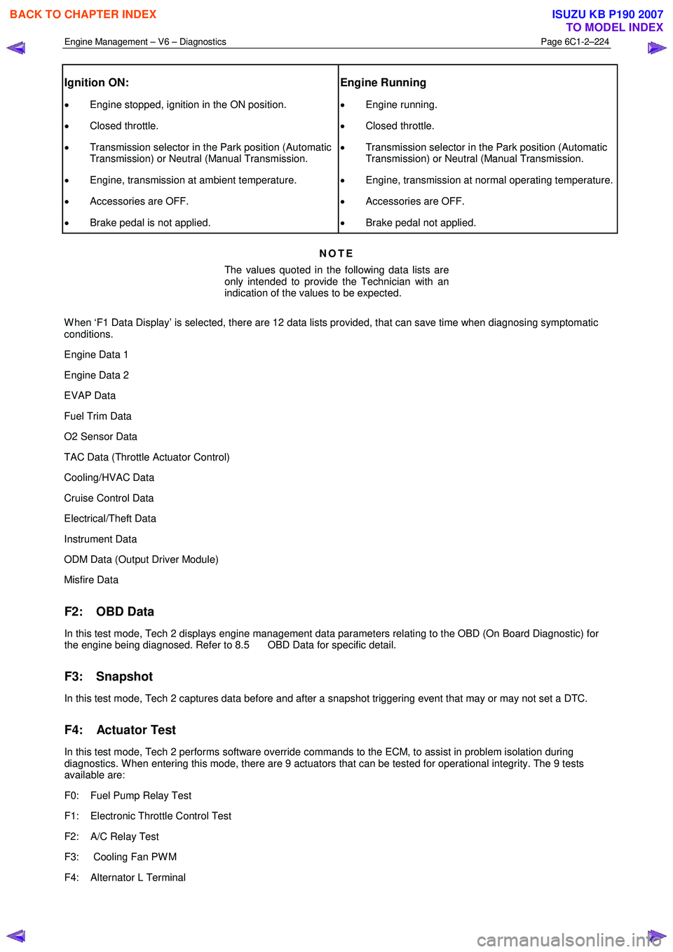
Ignition ON:
• Engine stopped, ignition in the ON position.
• Closed throttle.
• Transmission selector in the Park position (Automatic
Transmission) or Neutral (Manual Transmission.
• Engine, transmission at ambient temperature.
• Accessories are OFF.
• Brake pedal is not applied.
Engine Running
• Engine running.
• Closed throttle.
• Transmission selector in the Park position (Automatic
Transmission) or Neutral (Manual Transmission.
• Engine, transmission at normal operating temperature.
• Accessories are OFF.
• Brake pedal not applied.
NOTE
The values quoted in the following data lists are
only intended to provide the Technician with an
indication of the values to be expected.
W hen ‘F1 Data Display’ is selected, there are 12 data lists provided, that can save time when diagnosing symptomatic
conditions.
Engine Data 1
Engine Data 2
EVAP Data
Fuel Trim Data
O2 Sensor Data
TAC Data (Throttle Actuator Control)
Cooling/HVAC Data
Cruise Control Data
Electrical/Theft Data
Instrument Data
ODM Data (Output Driver Module)
Misfire Data
F2: OBD Data
In this test mode, Tech 2 displays engine management data parameters relating to the OBD (On Board Diagnostic) for
the engine being diagnosed. Refer to 8.5 OBD Data for specific detail.
F3: Snapshot
In this test mode, Tech 2 captures data before and after a snapshot triggering event that may or may not set a DTC.
F4: Actuator Test
In this test mode, Tech 2 performs software override commands to the ECM, to assist in problem isolation during
diagnostics. W hen entering this mode, there are 9 actuators that can be tested for operational integrity. The 9 tests
available are:
F0: Fuel Pump Relay Test
F1: Electronic Throttle Control Test
F2: A/C Relay Test
F3: Cooling Fan PW M
F4: Alternator L Terminal
BACK TO CHAPTER INDEX
TO MODEL INDEX
ISUZU KB P190 2007
Page 3503 of 6020
Engine Management – V6 – Diagnostics Page 6C1-2–225
F5: EVAP Purge Solenoid
F6: Engine Speed Control
F7: Starter Relay Test
F8: Fuel Injector Balance
F5: Additional Functions
W hen this selection is made from the Tech 2 screen, an additional two choices are provided:
F0: System Identification: In this mode, Tech 2 will display the engine identification screen.
F1: Security Information: W hen selected, this mode displays various engine management data parameters relating to the security system.
F6: Programming
W ithin this selection, there are five programming selections available:
F0: Immobiliser Link to ECM/PIM
F1: Reset ECU
F2: Fuel Trim Reset
F3: Reset Engine Oil Life
F4: Throttle Body Relearn
BACK TO CHAPTER INDEX
TO MODEL INDEX
ISUZU KB P190 2007