relay ISUZU KB P190 2007 Workshop Repair Manual
[x] Cancel search | Manufacturer: ISUZU, Model Year: 2007, Model line: KB P190, Model: ISUZU KB P190 2007Pages: 6020, PDF Size: 70.23 MB
Page 3814 of 6020
Automatic Transmission – 4L60E – Electrical Diagnosis Page 7C2–28
7 Ensure that all wiring harness connectors are fitted correctly and secure.
8 W hen steam or pressure cleaning vehicle components, such as engines, transmissions, etc., do not direct the cleaning nozzle at any system electrical wiring harness connectors or components.
9 Do not clear any DTCs unless instructed.
10 The fault must be present when using the Diagnostic Trouble Code (DTC) Diagnostic Tables. Otherwise, misdiagnosis or replacement of good parts may occur.
11 Do not touch any electronic control module connector pins or soldered components on the circuit board. This is required to avoid the possibility of electrostatic discharge damage.
12 Use only the test equipment specified in the diagnostic tables, as other test equipment may give incorrect results or damage good components.
13 Electronic control modules are designed to withstand normal current draws associated with vehicle operation. However, the following fault conditions or incorrect test procedure may overload internal control module circuits and
irreparably damage the control module:
• A short to voltage fault condition in any of the control module low reference circuits may cause internal and/or
sensor damage. Therefore, any short to voltage fault condition in the control module low reference circuits
must be rectified before replacing a faulty component.
• A short to ground fault condition in any of the control module 5 volts reference circuits may cause internal
control module and/or sensor damage. Therefore, any short to ground fault condition in the control module 5
volt reference circuits must be rectified before replacing a faulty component.
• W hen using a test light to test an electrical circuit, do not use any of the control module low reference circuits
or 5 volts reference circuits as a reference point. Otherwise, excessive current draw from the test light may
damage the control module.
14 Disregard DTCs that set while performing the following diagnostic Steps:
• Using the Tech 2 output control function, or
• Disconnecting a control module system sensor connector then switching the ignition ON.
15 After completing the required diagnostics and service operations, road test the vehicle to ensure correct system operation.
4.4 Preliminary Checks
The Preliminary Checks is a set of visual and physical checks or inspections that may quickly identify a control module
system fault condition:
1 Refer to relevant Service Techlines for information regarding the fault condition.
2 Ensure that the battery is fully charged.
3 Inspect the battery connections for corrosion or a loose terminal.
4 Ensure that all relevant control module system related fuses are serviceable.
5 Inspect for incorrect aftermarket theft deterrent devices, lights or mobile phone installation.
6 Ensure that there is no speaker magnet positioned too close to any electronic module that contains relays.
7 Inspect the system wiring harness for proper connections, pinches or cuts.
8 Ensure that all control module related electrical wiring connectors are fitted correctly.
9 Inspect the control module ground connections for corrosion, loose terminal or incorrect position.
10 Ensure that the resistance between the control module housing and the battery ground cable is less than 0.5 ohms.
11 Check that the control module and its mounting bracket is secure.
12 Check all control module related components for correct installation.
13 Check the control module and related wiring harness routing to ensure that no rubbing or cutting of the wiring harness by sharp body components can occur.
BACK TO CHAPTER INDEX
TO MODEL INDEX
ISUZU KB P190 2007
Page 3957 of 6020
Automatic Transmission – 4L60E – On-vehicle Servicing Page 7C4–44
b Starter motor, refer to 6D1-2 Starting System.
b Rear propeller shaft and for 4WD front propeller shaft, refer to 4A Propeller Shaft.
6 On 4WD vehicle, disconnect the harness two clips from the upper side of the transfer case.
7 From within the starter motor access hole, remove the three bolts (2) attaching the torque converter to the flexplate and discard, refer to Figure 7C4 – 62.
8 Remove the transmission support, refer to 3.7 Transmission Support and Mount.
9 Disconnect the fuel and EVAP pipes three brackets and clips, refer to 6C Fuel System – V6.
Before lowering the transmission take care of
the following:
• Do not strain the harness and connector
as the connector pins could be
permanently damaged.
• Ensure the inlet manifold does not hit the
firewall.
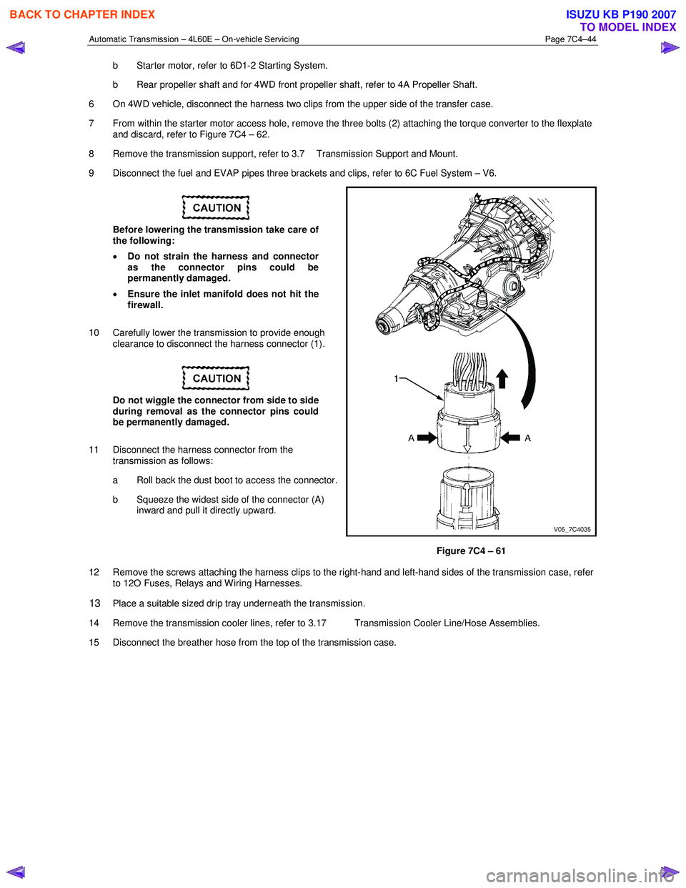
10 Carefully lower the transmission to provide enough clearance to disconnect the harness connector (1).
Do not wiggle the connector from side to side
during removal as the connector pins could
be permanently damaged.
11 Disconnect the harness connector from the transmission as follows:
a Roll back the dust boot to access the connector.
b Squeeze the widest side of the connector (A) inward and pull it directly upward.
Figure 7C4 – 61
12 Remove the screws attaching the harness clips to the right-hand and left-hand sides of the transmission case, refer to 12O Fuses, Relays and W iring Harnesses.
13 Place a suitable sized drip tray underneath the transmission.
14 Remove the transmission cooler lines, refer to 3.17 Transmission Cooler Line/Hose Assemblies.
15 Disconnect the breather hose from the top of the transmission case.
BACK TO CHAPTER INDEX
TO MODEL INDEX
ISUZU KB P190 2007
Page 3959 of 6020
Automatic Transmission – 4L60E – On-vehicle Servicing Page 7C4–46
Reinstall
1 If required on 4W D vehicle, reinstall the transfer case, refer to 7D Transfer Case and Adaptor Housing.
2 Ensure the transmission and the engine mating surfaces are clean and free of burrs.
3 Lubricate the torque converter spigot (7) with a small amount of high temperature wheel bearing grease, refer to Figure 7C4 – 62.
4 Install a new filler tube seal into the transmission case.
Support the transmission while installing the
attaching bolts to avoid damage to the torque
converter and flexplate. Do not have the
transmission hanging.
5 Bring the transmission up to the engine, inserting the filler tube and ensuring the locating dowels completely enter the torque converter housing.
6 Reconnect the breather hose to the top of the transmission case.
NOTE
The bolts attaching the torque converter housing
are facing forward except for the bolt in position ℑ
which is facing rearward.
7 With the transmission supported, install the bolt (1), nine places, attaching the torque converter housing to the engine and tighten to the correct torque specification following the sequence shown in
within Figure 7C4 – 62.
Torque converter housing attaching
bolt torque specification .......................... 52.0 – 66.0 Nm
8 Remove the access hole cover plate from the lower surface of the housing and push the torque converter forward to meet the flexplate, then hand start three new bolts (2) before tightening to the correct torque specification.
Reinstall the access hole cover plate.
Torque converter to flexplate attaching
bolt torque specification .......................... 60.0 – 70.0 Nm
9 Reinstall the bolt (3) and torque converter cover (4) on the transmission right-hand side and the bolt (5) and torque converter cover (6) on the transmission left-hand side, tighten the bolts to the correct torque specification.
Torque converter cover attaching
bolt torque specification .......................... 12.0 – 16.0 Nm
10 Reinstall the transmission fluid lines, refer to 3.17 Transmission Cooler Line/Hose Assemblies.
Prior to connecting the harness connector to
the transmission, check that all pins and
seals are in sound condition and the dust
boot is not torn or damaged.
11 Reconnect the transmission harness connector to the transmission as follows: a Push straight down on the connector body until a click is heard.
b Reinstall the dust boot ensuring it is correctly located.
12 Attach the harness clips to the right-hand and left-hand sides of the transmission case, refer to 12O Fuses, Relays and Wiring Harnesses.
13 On 4WD vehicle, connect the harness two clips from the upper side of the transfer case.
BACK TO CHAPTER INDEX
TO MODEL INDEX
ISUZU KB P190 2007
Page 4306 of 6020
7A2-22 TRANSMISSION CONTROL SYSTEM (JR405E)
Diagnostic System Check - Transmission Controls
Description
The Diagnostic System Check - Transmission Controls
is an organized approach to identifying a condition that
is created by a malfunction in the electronic
transmission control system. The Diagnostic System
Check must be the starting point for any driveability
concern. The Diagnostic System Check directs the
service technician to the next logical step in order to
diagnose the concern. Understanding and correctly
using the diagnostic table reduces diagnostic time, and
prevents the replacement of good parts.
Test Description
The numbers below refer to the step numbers on the
diagnostic table.
2. Lack of communication may be because of a partial
or a total malfunction of the serial data circuit.
8. If there are other modules with DTCs set, refer to the
DTC list. The DTC list directs you to the appropriate
diagnostic procedure. If the control module stores
multiple DTCs, diagnose the DTCs in the following
order:
• Component level DTCs, such as sensor DTCs, solenoid DTCs, actuator DTCs, and relay DTCs.
Diagnose the multiple DTCs within this category in
numerical order. Begin with the lowest numbered
DTC, unless the diagnostic table directs you
otherwise. Diagnostic System Check Transmission Controls
Important: • DO NOT perform this diagnostic if there is not a driveability concern, unless another procedure
directs you to this diagnostic.
• Before you proceed with diagnosis, search for applicable service bulletins.
• Unless a diagnostic procedure instructs you, DO NOT clear the DTCs.
• Ensure the battery has a full charge.
• Ensure the battery cables (+) (-) are clean and tight.
• Ensure the TCM grounds are clean, tight, and in the correct location.
• Ensure the TCM harness connectors are clean and correctly connected.
• Ensure the TCM terminals are clean and correctly mating.
• If there are gear ratio DTC's (P0731, P0732, P0733 or P0734), diagnose sensor DTCs and
solenoid DTCs first.
Diagnostic System Check - Transmission Controls
Step Action Value(s)Yes No
1 Install a scan tool.
Does the scan tool turn ON? —
Go to Step 2 Go to Scan Tool
Does Not Power Up
2 1. Turn ON the ignition, with the engine OFF.
2. Attempt to establish communication with the listed control modules.
•TCM
• Electronic hydraulic control unit (EHCU) [ABS module] (If so equipped)
• Supplemental restraint system (SRS) control module (If so equipped)
Does the scan tool communicate with all the listed
control modules? —
Go to Step 3 Go to Scan Tool
Does Not
Communicate with Keyword Device
3 Attempt to start the engine.
Does the engine start and idle? —
Go to Step 4 Go to Engine
Cranks but Does
Not Run in engine control section
4 Select the DTC display function for the following
control modules:
•TCM
• Engine control module (ECM)
Does the scan tool display any DTCs? —
Go to Step 5 Go to Step 9
5 Does the scan tool other control module
communication fault DTCs? —Go to Applicable
DTC Go to Step 6
BACK TO CHAPTER INDEX
TO MODEL INDEX
ISUZU KB P190 2007
Page 4320 of 6020
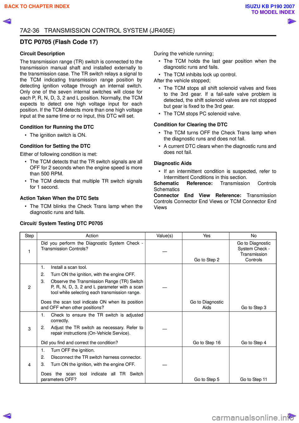
7A2-36 TRANSMISSION CONTROL SYSTEM (JR405E)
DTC P0705 (Flash Code 17)
Circuit Description
The transmission range (TR) switch is connected to the
transmission manual shaft and installed externally to
the transmission case. The TR switch relays a signal to
the TCM indicating transmission range position by
detecting ignition voltage through an internal switch.
Only one of the seven internal switches will close for
each P, R, N, D, 3, 2 and L position. Normally, the TCM
expects to detect one high voltage input for each
position. If the TCM detects more than one high voltage
input at the same time or no input, this DTC will set.
Condition for Running the DTC • The ignition switch is ON.
Condition for Setting the DTC
Either of following condition is met: • The TCM detects that the TR switch signals are all OFF for 2 seconds when the engine speed is more
than 500 RPM.
• The TCM detects that multiple TR switch signals for 1 second.
Action Taken When the DTC Sets • The TCM blinks the Check Trans lamp when the diagnostic runs and fails. During the vehicle running;
• The TCM holds the last gear position when the diagnostic runs and fails.
• The TCM inhibits lock up control.
After the vehicle stopped;
• The TCM stops all shift solenoid valves and fixes to the 3rd gear. If a fail-safe valve problem is
detected, the shift solenoid valves are not stopped
but gear is fixed to the 3rd gear.
• The TCM stops PC solenoid valve.
Condition for Clearing the DTC • The TCM turns OFF the Check Trans lamp when the diagnostic runs and does not fail.
• A current DTC clears when the diagnostic runs and does not fail.
Diagnostic Aids • If an intermittent condition is suspected, refer to Intermittent Conditions in this section.
Schematic Reference: Transmission Controls
Schematics
Connector End View Reference: Transmission
Controls Connector End Views or TCM Connector End
Views
Circuit/ System Testing DTC P0705
Step Action Value(s)Yes No
1 Did you perform the Diagnostic System Check -
Transmission Controls? —
Go to Step 2 Go to Diagnostic
System Check - Transmission Controls
2 1. Install a scan tool.
2. Turn ON the ignition, with the engine OFF.
3. Observe the Transmission Range (TR) Switch P, R, N, D, 3, 2 and L parameter with a scan
tool while selecting each transmission range.
Does the scan tool indicate ON when its position
and OFF when other positions? —
Go to Diagnostic Aids Go to Step 3
3 1. Check to ensure the TR switch is adjusted
correctly.
2. Adjust the TR switch as necessary. Refer to repair instructions (On-Vehicle Service).
Did you find and correct the condition? —
Go to Step 16 Go to Step 4
4 1. Turn OFF the ignition.
2. Disconnect the TR switch harness connector.
3. Turn ON the ignition, with the engine OFF.
Does the scan tool indicate all TR Switch
parameters OFF? —
Go to Step 5 Go to Step 11
BACK TO CHAPTER INDEX
TO MODEL INDEX
ISUZU KB P190 2007
Page 4337 of 6020
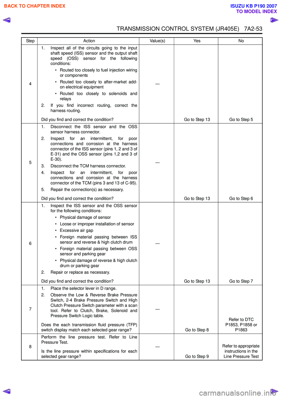
TRANSMISSION CONTROL SYSTEM (JR405E) 7A2-53
41. Inspect all of the circuits going to the input
shaft speed (ISS) sensor and the output shaft
speed (OSS) sensor for the following
conditions:
• Routed too closely to fuel injection wiring or components
• Routed too closely to after-market add- on electrical equipment
• Routed too closely to solenoids and relays
2. If you find incorrect routing, correct the harness routing.
Did you find and correct the condition? —
Go to Step 13 Go to Step 5
5 1. Disconnect the ISS sensor and the OSS
sensor harness connector.
2. Inspect for an intermittent, for poor connections and corrosion at the harness
connector of the ISS sensor (pins 1, 2 and 3 of
E-31) and the OSS sensor (pins 1,2 and 3 of
E-30).
3. Disconnect the TCM harness connector.
4. Inspect for an intermittent, for poor connections and corrosion at the harness
connector of the TCM (pins 3 and 13 of C-95).
5. Repair the connection(s) as necessary.
Did you find and correct the condition? —
Go to Step 13 Go to Step 6
6 1. Inspect the ISS sensor and the OSS sensor
for the following conditions:
• Physical damage of sensor
• Loose or improper installation of sensor
• Excessive air gap
• Foreign material passing between ISS sensor and reverse & high clutch drum
• Foreign material passing between OSS sensor and parking gear
• Physical damage of reverse & high clutch drum or parking gear
2. Repair or replace as necessary.
Did you find and correct the condition? —
Go to Step 13 Go to Step 7
7 1. Place the selector lever in D range.
2. Observe the Low & Reverse Brake Pressure Switch, 2-4 Brake Pressure Switch and High
Clutch Pressure Switch parameter with a scan
tool. Refer to Clutch, Brake, Solenoid and
Pressure Switch Logic table.
Does the each transmission fluid pressure (TFP)
switch display match each selected gear range? —
Go to Step 8 Refer to DTC
P1853, P1858 or P1863
8 Perform the line pressure test. Refer to Line
Pressure Test.
Is the line pressure within specifications for each
selected gear range? —
Go to Step 9 Refer to appropriate
instructions in the
Line Pressure Test
Step
Action Value(s)Yes No
BACK TO CHAPTER INDEX
TO MODEL INDEX
ISUZU KB P190 2007
Page 4376 of 6020
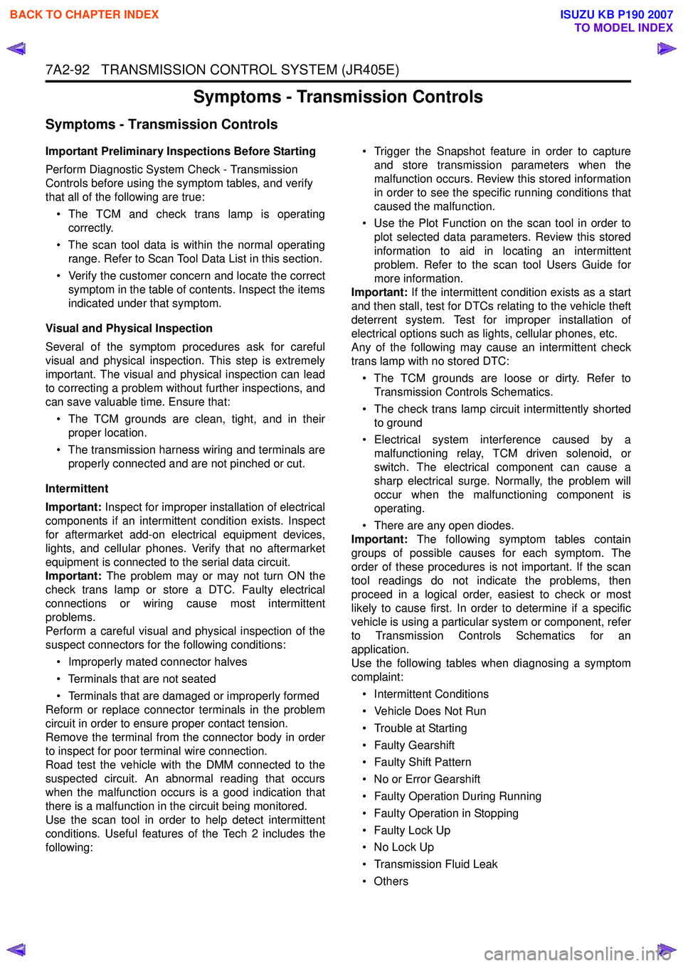
7A2-92 TRANSMISSION CONTROL SYSTEM (JR405E)
Symptoms - Transmission Controls
Symptoms - Transmission Controls
Important Preliminary Inspections Before Starting
Perform Diagnostic System Check - Transmission
Controls before using the symptom tables, and verify
that all of the following are true:
• The TCM and check trans lamp is operating correctly.
• The scan tool data is within the normal operating range. Refer to Scan Tool Data List in this section.
• Verify the customer concern and locate the correct symptom in the table of contents. Inspect the items
indicated under that symptom.
Visual and Physical Inspection
Several of the symptom procedures ask for careful
visual and physical inspection. This step is extremely
important. The visual and physical inspection can lead
to correcting a problem without further inspections, and
can save valuable time. Ensure that:
• The TCM grounds are clean, tight, and in their proper location.
• The transmission harness wiring and terminals are properly connected and are not pinched or cut.
Intermittent
Important: Inspect for improper installation of electrical
components if an intermittent condition exists. Inspect
for aftermarket add-on electrical equipment devices,
lights, and cellular phones. Verify that no aftermarket
equipment is connected to the serial data circuit.
Important: The problem may or may not turn ON the
check trans lamp or store a DTC. Faulty electrical
connections or wiring cause most intermittent
problems.
Perform a careful visual and physical inspection of the
suspect connectors for the following conditions:
• Improperly mated connector halves
• Terminals that are not seated
• Terminals that are damaged or improperly formed
Reform or replace connector terminals in the problem
circuit in order to ensure proper contact tension.
Remove the terminal from the connector body in order
to inspect for poor terminal wire connection.
Road test the vehicle with the DMM connected to the
suspected circuit. An abnormal reading that occurs
when the malfunction occurs is a good indication that
there is a malfunction in the circuit being monitored.
Use the scan tool in order to help detect intermittent
conditions. Useful features of the Tech 2 includes the
following: • Trigger the Snapshot feature in order to capture
and store transmission parameters when the
malfunction occurs. Review this stored information
in order to see the specific running conditions that
caused the malfunction.
• Use the Plot Function on the scan tool in order to plot selected data parameters. Review this stored
information to aid in locating an intermittent
problem. Refer to the scan tool Users Guide for
more information.
Important: If the intermittent condition exists as a start
and then stall, test for DTCs relating to the vehicle theft
deterrent system. Test for improper installation of
electrical options such as lights, cellular phones, etc.
Any of the following may cause an intermittent check
trans lamp with no stored DTC:
• The TCM grounds are loose or dirty. Refer to Transmission Controls Schematics.
• The check trans lamp circuit intermittently shorted to ground
• Electrical system interference caused by a malfunctioning relay, TCM driven solenoid, or
switch. The electrical component can cause a
sharp electrical surge. Normally, the problem will
occur when the malfunctioning component is
operating.
• There are any open diodes.
Important: The following symptom tables contain
groups of possible causes for each symptom. The
order of these procedures is not important. If the scan
tool readings do not indicate the problems, then
proceed in a logical order, easiest to check or most
likely to cause first. In order to determine if a specific
vehicle is using a particular system or component, refer
to Transmission Controls Schematics for an
application.
Use the following tables when diagnosing a symptom
complaint:
• Intermittent Conditions
• Vehicle Does Not Run
• Trouble at Starting
• Faulty Gearshift
• Faulty Shift Pattern
• No or Error Gearshift
• Faulty Operation During Running
• Faulty Operation in Stopping
• Faulty Lock Up
• No Lock Up
• Transmission Fluid Leak
•Others
BACK TO CHAPTER INDEX
TO MODEL INDEX
ISUZU KB P190 2007
Page 4378 of 6020
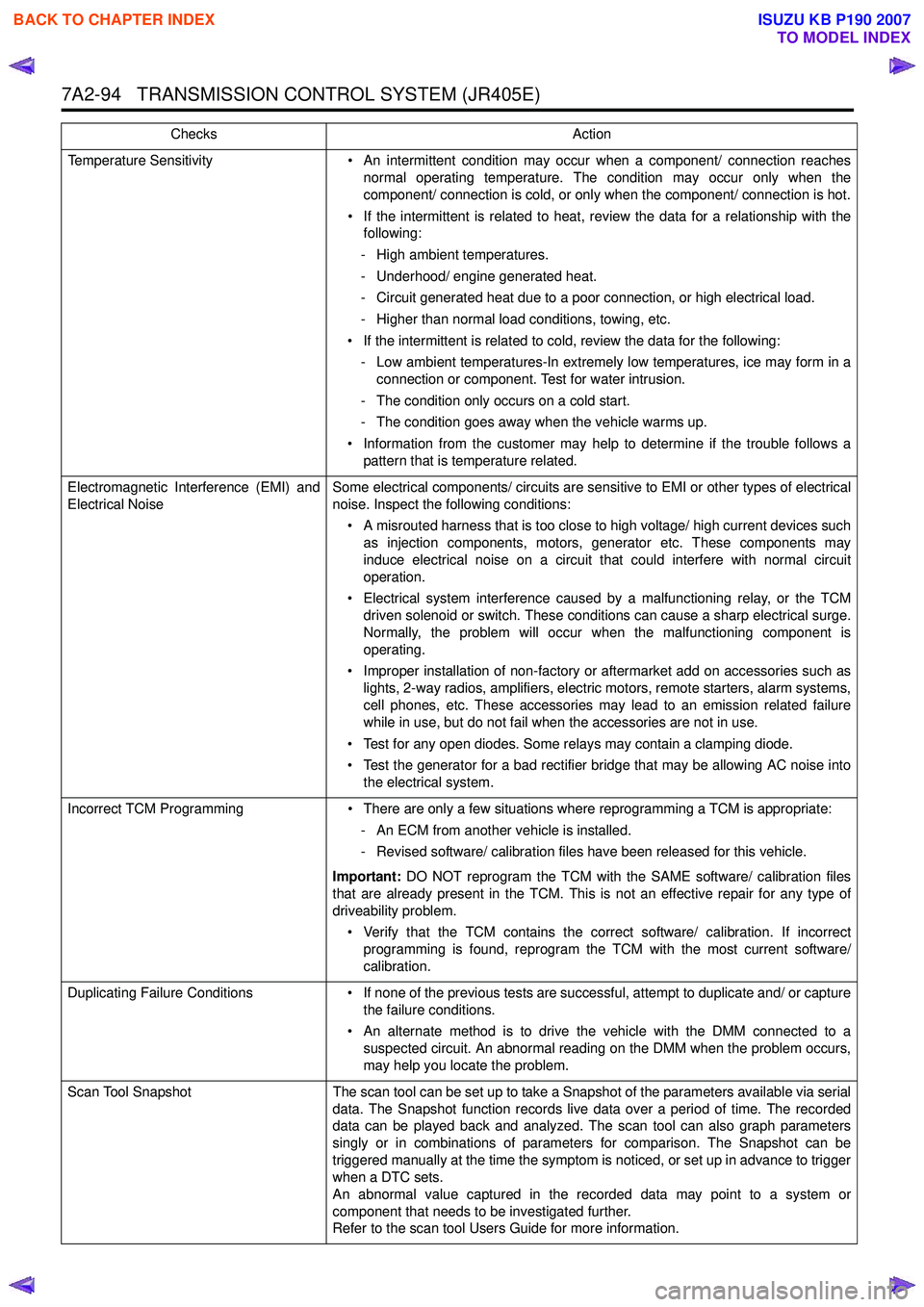
7A2-94 TRANSMISSION CONTROL SYSTEM (JR405E)
Temperature Sensitivity• An intermittent condition may occur when a component/ connection reaches
normal operating temperature. The condition may occur only when the
component/ connection is cold, or only when the component/ connection is hot.
• If the intermittent is related to heat, review the data for a relationship with the following:
- High ambient temperatures.
- Underhood/ engine generated heat.
- Circuit generated heat due to a poor connection, or high electrical load.
- Higher than normal load conditions, towing, etc.
• If the intermittent is related to cold, review the data for the following: - Low ambient temperatures-In extremely low temperatures, ice may form in a connection or component. Test for water intrusion.
- The condition only occurs on a cold start.
- The condition goes away when the vehicle warms up.
• Information from the customer may help to determine if the trouble follows a pattern that is temperature related.
Electromagnetic Interference (EMI) and
Electrical Noise Some electrical components/ circuits are sensitive to EMI or other types of electrical
noise. Inspect the following conditions:
• A misrouted harness that is too close to high voltage/ high current devices such as injection components, motors, generator etc. These components may
induce electrical noise on a circuit that could interfere with normal circuit
operation.
• Electrical system interference caused by a malfunctioning relay, or the TCM driven solenoid or switch. These conditions can cause a sharp electrical surge.
Normally, the problem will occur when the malfunctioning component is
operating.
• Improper installation of non-factory or aftermarket add on accessories such as lights, 2-way radios, amplifiers, electric motors, remote starters, alarm systems,
cell phones, etc. These accessories may lead to an emission related failure
while in use, but do not fail when the accessories are not in use.
• Test for any open diodes. Some relays may contain a clamping diode.
• Test the generator for a bad rectifier bridge that may be allowing AC noise into the electrical system.
Incorrect TCM Programming • There are only a few situations where reprogramming a TCM is appropriate:
- An ECM from another vehicle is installed.
- Revised software/ calibration files have been released for this vehicle.
Important: DO NOT reprogram the TCM with the SAME software/ calibration files
that are already present in the TCM. This is not an effective repair for any type of
driveability problem.
• Verify that the TCM contains the correct software/ calibration. If incorrect programming is found, reprogram the TCM with the most current software/
calibration.
Duplicating Failure Conditions • If none of the previous tests are successful, attempt to duplicate and/ or capture
the failure conditions.
• An alternate method is to drive the vehicle with the DMM connected to a suspected circuit. An abnormal reading on the DMM when the problem occurs,
may help you locate the problem.
Scan Tool Snapshot The scan tool can be set up to take a Snapshot of the parameters available via serial
data. The Snapshot function records live data over a period of time. The recorded
data can be played back and analyzed. The scan tool can also graph parameters
singly or in combinations of parameters for comparison. The Snapshot can be
triggered manually at the time the symptom is noticed, or set up in advance to trigger
when a DTC sets.
An abnormal value captured in the recorded data may point to a system or
component that needs to be investigated further.
Refer to the scan tool Users Guide for more information.
Checks
Action
BACK TO CHAPTER INDEX
TO MODEL INDEX
ISUZU KB P190 2007
Page 4435 of 6020
TRANSMISSION CONTROL SYSTEM (JR405E) 7A2-151
The transmission fluid temperature (TFT) sensor is part
of the harness assembly. The sensor is a variable
resistor and it measures the temperature of the
transmission fluid. When the TFT sensor is cold, the
sensor resistance is high. When the transmission fluid
temperature increases, the sensor resistance
decreases. With high sensor resistance, the TCM
detects a high voltage on the signal circuit. With lower
sensor resistance, the TCM detects a lower voltage on
the signal circuit.
If the fluid temperature increases to 135 °C (275 °F), the
TCM illuminates A/T Oil Temp lamp on the instrument
panel cluster. When the fluid temperature deceases
below 125 °C (257 °F), the lamp goes off.
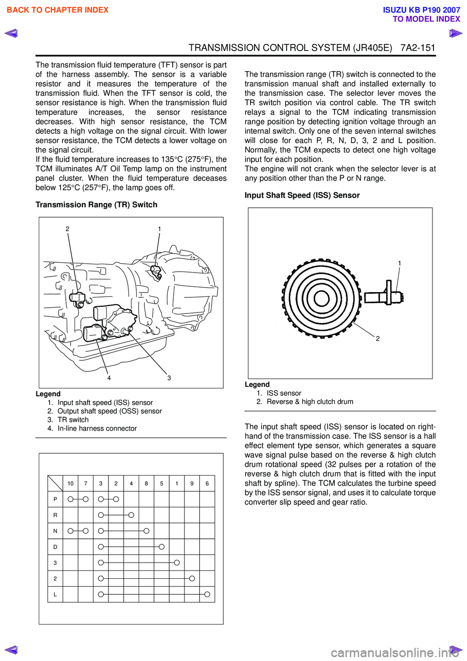
Transmission Range (TR) Switch
Legend 1. Input shaft speed (ISS) sensor
2. Output shaft speed (OSS) sensor
3. TR switch
4. In-line harness connector
The transmission range (TR) switch is connected to the
transmission manual shaft and installed externally to
the transmission case. The selector lever moves the
TR switch position via control cable. The TR switch
relays a signal to the TCM indicating transmission
range position by detecting ignition voltage through an
internal switch. Only one of the seven internal switches
will close for each P, R, N, D, 3, 2 and L position.
Normally, the TCM expects to detect one high voltage
input for each position.
The engine will not crank when the selector lever is at
any position other than the P or N range.
Input Shaft Speed (ISS) Sensor
Legend 1. ISS sensor
2. Reverse & high clutch drum
The input shaft speed (ISS) sensor is located on right-
hand of the transmission case. The ISS sensor is a hall
effect element type sensor, which generates a square
wave signal pulse based on the reverse & high clutch
drum rotational speed (32 pulses per a rotation of the
reverse & high clutch drum that is fitted with the input
shaft by spline). The TCM calculates the turbine speed
by the ISS sensor signal, and uses it to calculate torque
converter slip speed and gear ratio.
3
1
24
P
R
N
D
3
2
L
10732485196
1
2
BACK TO CHAPTER INDEX
TO MODEL INDEX
ISUZU KB P190 2007
Page 4918 of 6020
7D1-44 TRANSFER CONTROL SYSTEM
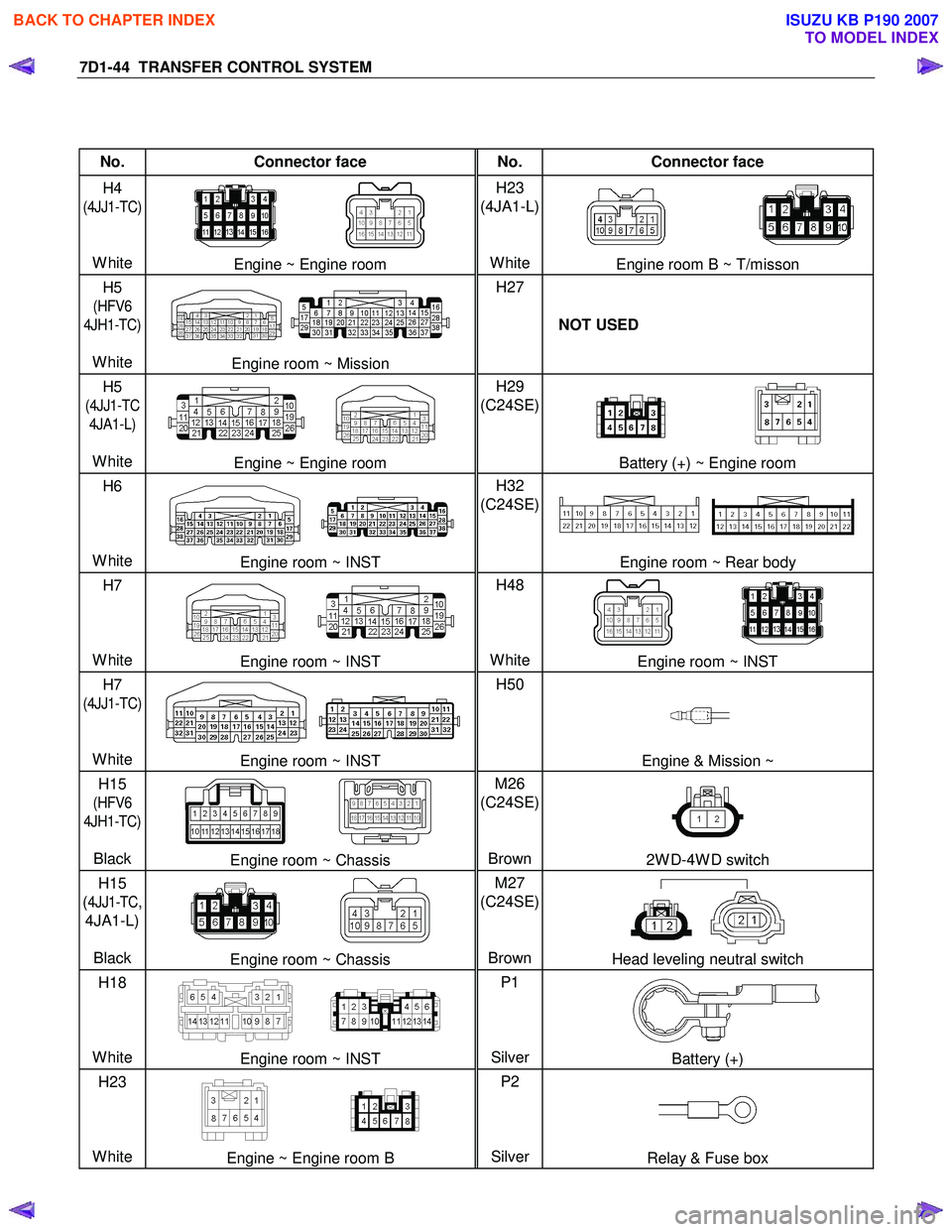
No. Connector face No. Connector face
H4
(4JJ1-TC)
White
Engine ~ Engine room H23
(4JA1-L)
WhiteEngine room B ~ T/misson
H5
(HFV6
4JH1-TC)
White
Engine room ~ Mission H27
NOT USED
H5
(4JJ1-TC
4JA1-L)
White
Engine ~ Engine room H29
(C24SE)
Battery (+) ~ Engine room
H6
White
Engine room ~ INST H32
(C24SE)
Engine room ~ Rear body
H7
White
Engine room ~ INST H48
WhiteEngine room ~ INST
H7
(4JJ1-TC)
White
Engine room ~ INST H50
Engine & Mission ~
H15
(HFV6
4JH1-TC)
Black
Engine room ~ Chassis M26
(C24SE)
Brown2W D-4W D switch
H15
(
4JJ1-TC,
4JA1-L)
Black
Engine room ~ Chassis M27
(C24SE)
BrownHead leveling neutral switch
H18
White
Engine room ~ INST P1
SilverBattery (+)
H23
White
Engine ~ Engine room B P2
SilverRelay & Fuse box
BACK TO CHAPTER INDEX
TO MODEL INDEX
ISUZU KB P190 2007