display ISUZU KB P190 2007 Workshop Repair Manual
[x] Cancel search | Manufacturer: ISUZU, Model Year: 2007, Model line: KB P190, Model: ISUZU KB P190 2007Pages: 6020, PDF Size: 70.23 MB
Page 3634 of 6020

Starting System – V6 Page 6D1-2–26
Reassemble
1 Reassemble the solenoid in the reverse order of the disassembly procedure noting the following points.
Dry all parts thoroughly before assembly,
taking care not to breathe in any vapours.
2 Lightly coat the solenoid switch plunger with 10% molybdenum disulphide grease.
Excess grease can enter the contact chamber
of the solenoid switch and cause contact
problems. Do not use too much grease.
3 Hook the plunger over the fork lever.
4 Insert the return spring into the plunger.
5 Slide solenoid switch over the plunger.
6 Align the solenoid switch with drive-end housing ensuring the solenoid switch terminal P – 4 faces away from the pole housing.
7 Install and tighten the solenoid switch mounting screws.
Solenoid switch mounting screw
torque specification .....................................4.1 – 7.6 Nm
8 W ith the starter motor reassembled, perform a No Load Test, refer to 4.3 Starter Motor Bench Tests.
9 If the starter motor fails the No Load Test specification, replace the starter motor.
4.5 Solenoid Switch Tests
Test the Solenoid Switch
1 Inspect the solenoid switch for any external damage.
2 Replace the solenoid switch if it displays significant damage.
3 Install the return spring and plunger into the solenoid switch.
4 Check the movement of the plunger, as follows: a Depress the plunger fully.
b Release the plunger.
c If the plunger sticks or binds in the switch bore, clean or replace the solenoid switch
assembly as required.
Figure 6D1-2 – 22
BACK TO CHAPTER INDEX
TO MODEL INDEX
ISUZU KB P190 2007
Page 3645 of 6020

Battery Page 6D1-3–5
This time is measured as the time taken for the battery voltage to reduce to 10.5 V from the following initial conditions:
• a fully charged battery at 25 °C, and
• discharged at a constant current of 25 A.
Cold Cranking Amps
The CCA rating indicates the ability of the battery to maintain enough voltage for ignition requirements while supplying
engine cranking current for long enough to start the engine under severely cold conditions.
The rating is the minimum amperage maintained when the engine is cranked for 30 seconds. The battery must maintain
at least 7.2 V at 18 °C.
Ratings
A specification label on the top of the battery displays the original equipment part number.
All vehicles are fitted with a low maintenance, 85 minute RC and 430 CCA battery.
BACK TO CHAPTER INDEX
TO MODEL INDEX
ISUZU KB P190 2007
Page 3665 of 6020

Powertrain Interface Module – V6 Page 6E1–4
Conditions for Setting the DTC........................................................................................................................... 56
Conditions for Clearing the DTC ................................................................................................ ........................ 56
Additional Information......................................................................................................................................... 56
DTC P0633 Diagnostic Table..................................................................................................... .......................... 56
9.15 DTC P1611 – Wrong Security Code Entered........................................................................................ .............. 57
DTC Description ................................................................................................................................................... 57
Circuit Description ............................................................................................................................................... 57
Additional Information......................................................................................................... ................................ 57
Conditions for Running the DTC ................................................................................................. ....................... 58
Conditions for Setting the DTC........................................................................................................................... 58
Action Taken When the DTC Sets ................................................................................................. ..................... 58
Conditions for Clearing the DTC ........................................................................................................................ 58
Test Description ................................................................................................................................................... 58
DTC P1611 Diagnostic Table..................................................................................................... .......................... 58
9.16 DTC B0981 – 3rd Start Switch Signal Malfunction ............................................................................................. 59
DTC Description ................................................................................................................................................... 59
Circuit Description ............................................................................................................................................... 59
Additional Information......................................................................................................... ................................ 59
Conditions for Running the DTC ................................................................................................. ....................... 59
Conditions for Setting the DTC........................................................................................................................... 60
Action Taken When the DTC Sets ................................................................................................. ..................... 60
Conditions for Clearing the DTC ........................................................................................................................ 60
Test Description ................................................................................................................................................... 60
DTC B0980 Diagnostic Table ..................................................................................................... ......................... 60
10 Diagnostics For Non DTC Faults ................................................................................................. .......62
10.1 PRND32L Display Diagnostics ............................................................................................... ................................ 62
Circuit Description ............................................................................................................................................... 62
Additional Information......................................................................................................... ................................ 62
Test Description ................................................................................................................................................... 62
PRND32L Display Diagnostic Table ............................................................................................... .................... 63
10.2 Warning Signal and Status Indicators Diagnostics.......................................................................... .................... 64
Circuit Description ............................................................................................................................................... 64
Additional Information......................................................................................................... ................................ 64
Test Description ................................................................................................................................................... 64
Hard-wired Warning Signals ..................................................................................................... .......................... 65
Warning Signal and Status Indicator Diagnostic Table ........................................................................... ......... 65
10.3 Tachometer Diagnostics......................................................................................................................................... 67
Circuit Description ............................................................................................................................................... 67
Additional Information......................................................................................................... ................................ 67
Test Description ................................................................................................................................................... 67
Tachometer Diagnostic Table .................................................................................................... ......................... 67
10.4 Temperature Gauge Diagnostics ............................................................................................. .............................. 69
Circuit Description ............................................................................................................................................... 69
Additional Information......................................................................................................... ................................ 69
Test Description ................................................................................................................................................... 69
Temperature Gauge Diagnostic Table ............................................................................................. .................. 70
11 Service Operations ...............................................................................................................................71
11.1 Safety and Precautionary Measures .................................................................................................................. 71
11.2 Powertrain Interface Module ............................................................................................................................... 71
Remove ................................................................................................................................................................. 72
Reinstall ................................................................................................................................................................ 72
11.3 Vertical Acceleration Sensor ................................................................................................... ........................... 73
Remove ................................................................................................................................................................. 73
Reinstall ................................................................................................................................................................ 73
12 PIM Security and Programming ................................................................................................... .......74
BACK TO CHAPTER INDEX
TO MODEL INDEX
ISUZU KB P190 2007
Page 3666 of 6020

Powertrain Interface Module – V6 Page 6E1–5
12.1 Security and Programming Information............................................................................................................. 74
Car Pass Card ...................................................................................................................................................... 74
Security Code ....................................................................................................................................................... 74
Tech 2 PIM Security Information Data List ...................................................................................... .................. 74
12.2 PIM Reset Procedure ........................................................................................................................................... 75
12.3 PIM Configuration ................................................................................................................................................ 76
Configuring the PIM ............................................................................................................ ................................. 76
Programming the VIN ............................................................................................................ .............................. 76
12.4 Immobiliser Link to ECM / PIM .................................................................................................. .......................... 77
13 Powertrain Interface Module – Tech 2 Functions .............................................................................79
13.1 Introduction .......................................................................................................................................................... 79
13.2 Tech 2 Functions ............................................................................................................... .................................. 79
F0: Diagnostic Trouble Codes ................................................................................................... ......................... 79
F1: Diagnostic Data Display................................................................................................................................ 79
F2: Snapshot Options.......................................................................................................................................... 80
F3: Miscellaneous Tests........................................................................................................ .............................. 80
F4: Additional Functions ..................................................................................................................................... 80
F5: Program .......................................................................................................................................................... 80
F6: Security .......................................................................................................................................................... 80
13.3 Powertrain Interface Module Data List .......................................................................................... ..................... 81
Diagnostic Data Display ...................................................................................................................................... 81
13.4 Miscellaneous Tests ............................................................................................................................................ 82
F0: Warnings ........................................................................................................................................................ 82
F1: Status Indicators .......................................................................................................... ................................. 82
F2: Gauge Control Tests ........................................................................................................ ............................. 82
13.5 Security................................................................................................................................................................. 83
F0: Immobiliser Link To ECM/PIM ................................................................................................ ...................... 83
F1: Reset PIM ....................................................................................................................................................... 83
F2: Security Information ....................................................................................................... ............................... 83
14 Specifications .......................................................................................................................................85
15 Torque Wrench Specifications................................................................................................... .........86
16 Special Tools ........................................................................................................................................87
BACK TO CHAPTER INDEX
TO MODEL INDEX
ISUZU KB P190 2007
Page 3677 of 6020

Powertrain Interface Module – V6 Page 6E1–16
Tech 2 PIM Diagnostic Tests
Tech 2 Limitations
Some DTCs trigger other DTCs to set, which causes Tech 2 to display multiple DTCs. In those situations, Tech 2 may
display more DTCs than is needed to rectify a fault.
W hen Tech 2 displays an output function, it displays only the command given by the PIM. If a connector is disconnected,
that fault will not register in the PIM output function. Tech 2 does not verify the command action.
The service technician must understand the system being diagnosed as well as the correct use and limitations of Tech 2
to be able to perform diagnostic procedures efficiently and successfully.
Tech 2 Intermittent Fault Tests
The following are lists of Tech 2 diagnostic tests that may be used to diagnose intermittent faults:
• W iggle test the suspected PIM wiring harness and connector while observing Tech 2 operating parameters of the
circuit being tested. If Tech 2 read-out fluctuates during this procedure, check the wiring harness circuit for loose
connection.
• Road test the vehicle in conditions that trigger the intermittent fault while an assistant observes the suspected Tech
2 operating parameter data.
• Capture and store data in the Snapshot mode when the fault occurs. The stored data may be replayed at a slower
rate to aid in diagnostics. Refer to Tech 2 User Instructions for more information on the Snapshot function.
• Operate suspected components to test their operation using Tech 2 Output Control Data.
BACK TO CHAPTER INDEX
TO MODEL INDEX
ISUZU KB P190 2007
Page 3687 of 6020

Powertrain Interface Module – V6 Page 6E1–26
Step Action Yes No
4
Using Tech 2, attempt to communicate with the PIM.
Does Tech 2 communicate with the PIM? Go to Step 5 Refer to
7.3 Powertrain Interface Module –
Module
Communication Check Failure
Diagnostic Table
5 Using Tech 2, view and record all DTCs.
Does Tech 2 display any DTCs? Go to Step 6 Refer to
Intermittent Fault Conditions.
6 Does DTC C0550 fail this ignition cycle? Refer to
9.1 DTC
C0550 – PIM
Internal Fault
Diagnostic Table Go to Step 7
7 Does DTC U2100 fail this ignition cycle? Refer to
9.2 DTC
U2100 – No
Communication
W ith CAN Bus (High Speed) Diagnostic
Table Go to Step 8
8 Does DTC U2106 fail this ignition cycle? Refer to
9.4 DTC
U2106 – CAN Bus
No Communication
W ith Transmission Control Module Go to Step 9
9
Does DTC U2105 fail this ignition cycle? Refer to
9.3 DTC
U2105 – CAN Bus
No Communication
W ith Engine Control Module Diagnostic
Table Go to Step 10
10 Does Tech 2 display multiple DTCs? Refer to
the DTC Table of
the fault condition
that is most likely to
trigger multiple
DTCs. Refer to
4.1 Diagnostic General
Descriptions for information on
multiple DTCs fault condition Refer to the relevant
DTC table
When all diagnosis and repairs are completed, clear all DTCs and check the system for correct operation.
BACK TO CHAPTER INDEX
TO MODEL INDEX
ISUZU KB P190 2007
Page 3689 of 6020

Powertrain Interface Module – V6 Page 6E1–28
Step Action Yes No
11
1 Using Tech 2, clear all DTCs.
2 Switch off the ignition for 30 seconds.
3 Check for DTCs.
Does Tech 2 display any PIM DTCs? Refer to
7.2 Diagnostic System Check Go to Step 7
12
Does Tech 2 display any other DTCs? Refer to the
appropriate Section System OK
When all diagnosis and repairs are completed, clear all DTCs and check the system for correct operation.
BACK TO CHAPTER INDEX
TO MODEL INDEX
ISUZU KB P190 2007
Page 3692 of 6020

Powertrain Interface Module – V6 Page 6E1–31
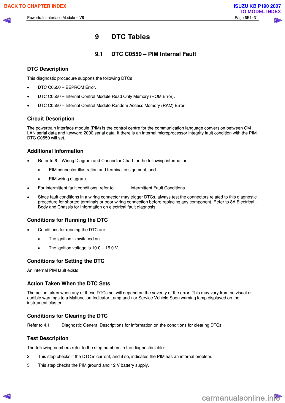
9 DTC Tables
9.1 DTC C0550 – PIM Internal Fault
DTC Description
This diagnostic procedure supports the following DTCs:
• DTC C0550 – EEPROM Error.
• DTC C0550 – Internal Control Module Read Only Memory (ROM Error).
• DTC C0550 – Internal Control Module Random Access Memory (RAM) Error.
Circuit Description
The powertrain interface module (PIM) is the control centre for the communication language conversion between GM
LAN serial data and keyword 2000 serial data. If there is an internal microprocessor integrity fault condition with the PIM,
DTC C0550 will set.
Additional Information
• Refer to 6 W iring Diagram and Connector Chart for the following information:
• PIM connector illustration and terminal assignment, and
• PIM wiring diagram.
• For intermittent fault conditions, refer to Intermittent Fault Conditions.
• Since fault conditions in a wiring connector may trigger DTCs, always test the connectors related to this diagnostic
procedure for shorted terminals or poor wiring connection before replacing any component. Refer to 8A Electrical -
Body and Chassis for information on electrical fault diagnosis.
Conditions for Running the DTC
• Conditions for running the DTC are:
• The ignition is switched on.
• The ignition voltage is 10.0 – 16.0 V.
Conditions for Setting the DTC
An internal PIM fault exists.
Action Taken When the DTC Sets
The action taken when any of these DTCs set will depend on the severity of the error. This may vary from no visual or
audible warnings to a Malfunction Indicator Lamp and / or Service Vehicle Soon warning lamp displayed on the
instrument cluster.
Conditions for Clearing the DTC
Refer to 4.1 Diagnostic General Descriptions for information on the conditions for clearing DTCs.
Test Description
The following numbers refer to the step numbers in the diagnostic table:
2 This step checks if the DTC is current, and if so, indicates the PIM has an internal problem.
3 This step checks the PIM ground and 12 V battery supply.
BACK TO CHAPTER INDEX
TO MODEL INDEX
ISUZU KB P190 2007
Page 3693 of 6020

Powertrain Interface Module – V6 Page 6E1–32
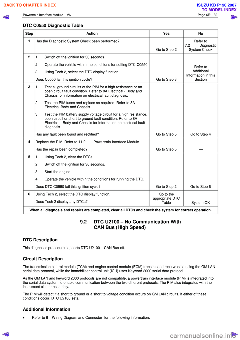
DTC C0550 Diagnostic Table
Step Action Yes No
1
Has the Diagnostic System Check been performed?
Go to Step 2 Refer to
7.2 Diagnostic System Check
2 1 Switch off the ignition for 30 seconds.
2 Operate the vehicle within the conditions for setting DTC C0550.
3 Using Tech 2, select the DTC display function.
Does C0550 fail this ignition cycle? Go to Step 3 Refer to
Additional
Information in this Section
3 1 Test all ground circuits of the PIM for a high resistance or an
open circuit fault condition. Refer to 8A Electrical - Body and
Chassis for information on electrical fault diagnosis.
2 Test the PIM fuses and replace as required. Refer to 8A Electrical-Body and Chassis.
3 Test the PIM battery supply voltage circuit for a high resistance, open circuit or short to ground fault condition. Refer to 8A
Electrical - Body and Chassis for information on electrical fault
diagnosis.
Has any fault been found and rectified? Go to Step 5 Go to Step 4
4 Replace the PIM. Refer to 11.2 Powertrain Interface Module.
Has the repair been completed? Go to Step 5 —
5 1 Using Tech 2, clear the DTCs.
2 Switch off the ignition for 30 seconds.
3 Start the engine.
4 Operate the vehicle within the conditions for running the DTC.
Does DTC C0550 fail this ignition cycle? Go to Step 2 Go to Step 6
6 Using Tech 2, select the DTC display function.
Does Tech 2 display any DTCs? Go to the
appropriate DTC
Table System OK
When all diagnosis and repairs are completed, clear all DTCs and check the system for correct operation.
9.2 DTC U2100 – No Communication With CAN Bus (High Speed)
DTC Description
This diagnostic procedure supports DTC U2100 – CAN Bus-off.
Circuit Description
The transmission control module (TCM) and engine control module (ECM) transmit and receive data using the GM LAN
serial data protocol, while the immobiliser control unit (ICU) uses Keyword 2000 serial data protocol.
As the GM LAN and keyword 2000 protocols are not compatible, a powertrain interface module (PIM) is integrated into
the serial data system to enable communication between the two different protocols. The PIM also integrates with the
instrument cluster assembly.
The PIM will detect if a short to ground or a short to voltage condition occurs on GM LAN circuits. If either of these
conditions occur, DTC U2100 sets.
Additional Information
• Refer to 6 W iring Diagram and Connector for the following information:
BACK TO CHAPTER INDEX
TO MODEL INDEX
ISUZU KB P190 2007
Page 3694 of 6020

Powertrain Interface Module – V6 Page 6E1–33
• PIM connector illustration and terminal assignment, and
• PIM wiring diagram.
• For intermittent fault conditions, refer to Intermittent Fault Conditions.
• Since fault conditions in a wiring connector may trigger DTCs, always test the connectors related to this diagnostic
procedure for shorted terminals or poor wiring connection before replacing any component. Refer to 8A Electrical -
Body and Chassis for information on electrical fault diagnosis.
Conditions for Running the DTC
Conditions for running the DTC are:
• The ignition is switched on.
• The ignition voltage is 10.0 – 16.0 V.
Conditions for Setting the DTC
The PIM detects a short to ground or short to voltage on the GM LAN circuits when the ignition is switched on and the
short condition exists for greater than five seconds.
NOTE
This DTC will only set when the ignition has
initially been turned to the ON position, and will
not set when the vehicle is being driven.
Action Taken When the DTC Sets
• W hen the DTC sets, the following warning lamps are displayed on the instrument cluster:
• Malfunction Indicator Lamp, and
• Service Vehicle Soon.
Conditions for Clearing the DTC
Refer to 4.1 Diagnostic General Descriptions for information on the conditions for clearing DTCs.
Test Description
The following numbers refer to the step numbers in the diagnostic table:
3 This step establishes if there is a fault with the ECM.
6 This step tests GM LAN serial data circuits between the TCM and the ECM.
8 This step tests GM LAN serial data circuits between the PIM and ECM (vehicles with manual transmission) or PIM and TCM (vehicles with automatic transmission).
9 This step tests GM LAN serial data circuits between the PIM and the data link connector.
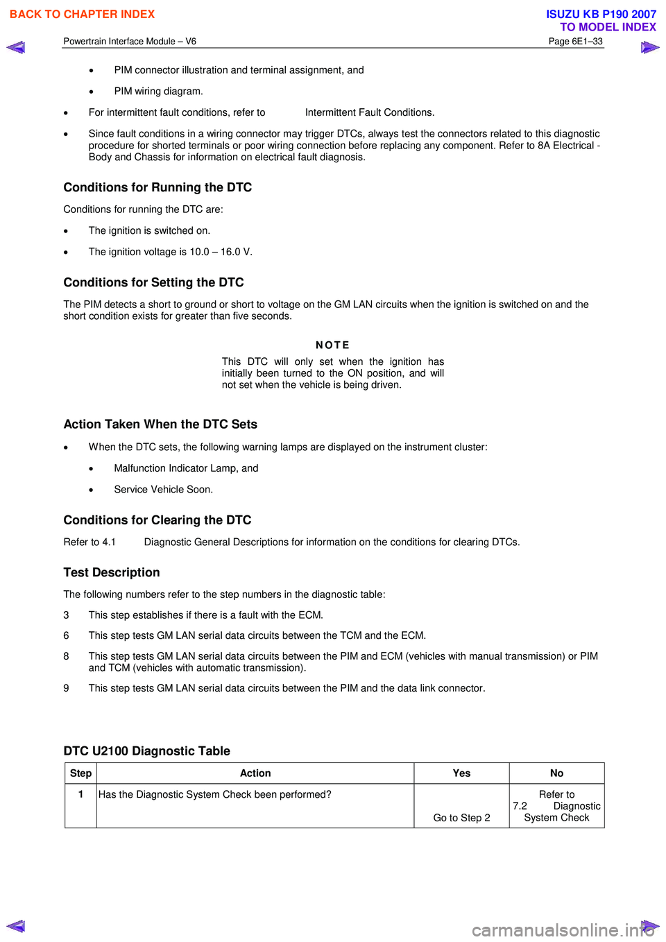
DTC U2100 Diagnostic Table
Step Action Yes No
1
Has the Diagnostic System Check been performed?
Go to Step 2 Refer to
7.2 Diagnostic System Check
BACK TO CHAPTER INDEX
TO MODEL INDEX
ISUZU KB P190 2007