display ISUZU KB P190 2007 Workshop Repair Manual
[x] Cancel search | Manufacturer: ISUZU, Model Year: 2007, Model line: KB P190, Model: ISUZU KB P190 2007Pages: 6020, PDF Size: 70.23 MB
Page 3728 of 6020

Powertrain Interface Module – V6 Page 6E1–67
10.3 Tachometer Diagnostics
Circuit Description
The powertrain interface module (PIM) receives the tachomer signal from the engine control module (ECM), it is then
sent to the instrument cluster by the PIM via a hard wired connection to drive the tachometer which displays the engine
RPM. Some of these components do not set a DTC, in the event of a component failure. The following diagnostic
procedures are devised to assist in these cases.
Additional Information
• Refer to 7.2 Diagnostic System Check to monitor DTC’s.
• Refer to 8A Electrical Body and Chassis for the following information:
• ECM wiring diagram.
• Refer to 6 W iring Diagram and Connector Chart for the following information:
• PIM connector illustration and terminal assignment, and
• PIM wiring diagram.
• For intermittent faults, refer to Intermittent Fault Conditions.
• Check for an intermittent fault in the wiring harness or connectors, if a fault cannot be found the system is
serviceable.
Since fault conditions in a wiring connector may trigger DTCs, always test the connectors related to this diagnostic
procedure for shorted terminals or poor wiring connection before replacing any component. Refer to 8A Electrical - Body
and Chassis for information on electrical fault diagnosis.
Test Description
The following numbers refer to the step numbers in the diagnostic table:
1 This step tests for DTC’s in the overall system.
2 This step uses the instrument cluster self test to check the function of the tachometer.
3 This step uses Tech 2 to drive the tachometer.
6 This step tests for tachometer drive frequency.
10 This step tests the in-vehicle function of the tachometer.
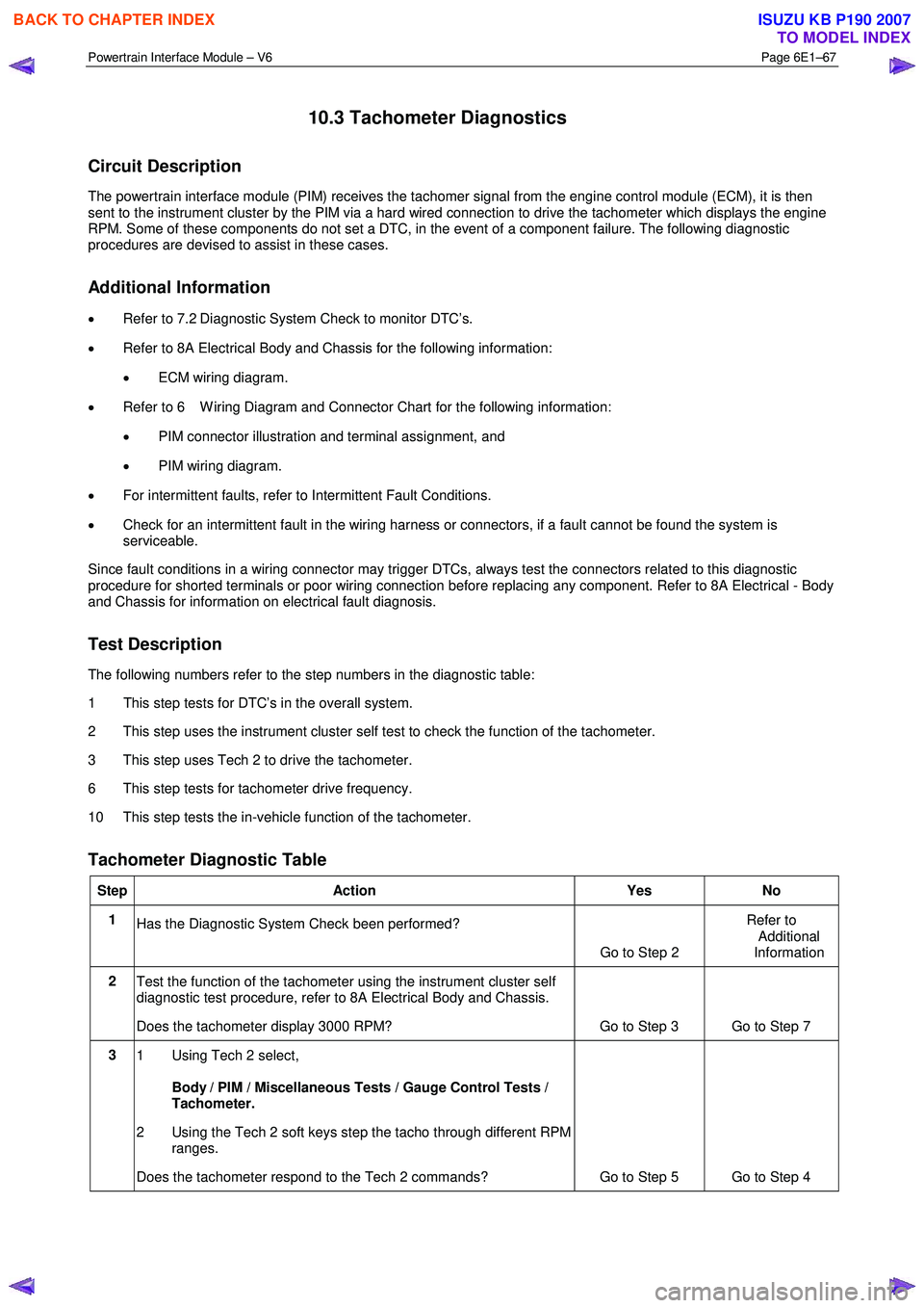
Tachometer Diagnostic Table
Step Action Yes No
1
Has the Diagnostic System Check been performed?
Go to Step 2 Refer to
Additional
Information
2 Test the function of the tachometer using the instrument cluster self
diagnostic test procedure, refer to 8A Electrical Body and Chassis.
Does the tachometer display 3000 RPM? Go to Step 3 Go to Step 7
3 1 Using Tech 2 select,
Body / PIM / Miscellaneous Tests / Gauge Control Tests /
Tachometer.
2 Using the Tech 2 soft keys step the tacho through different RPM ranges.
Does the tachometer respond to the Tech 2 commands? Go to Step 5 Go to Step 4
BACK TO CHAPTER INDEX
TO MODEL INDEX
ISUZU KB P190 2007
Page 3731 of 6020

Powertrain Interface Module – V6 Page 6E1–70
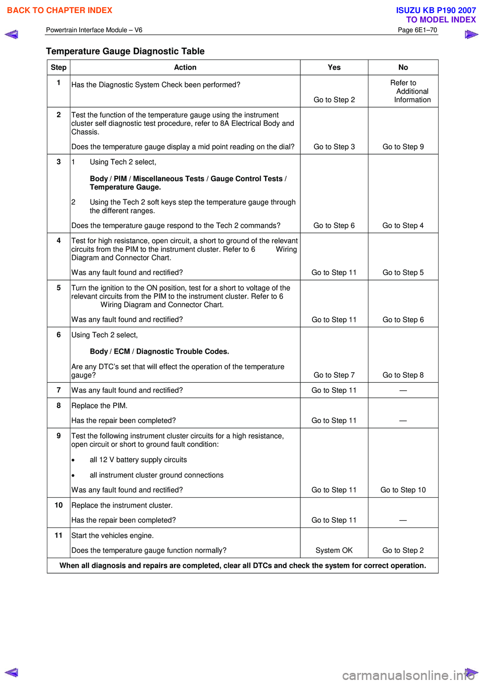
Temperature Gauge Diagnostic Table
Step Action Yes No
1
Has the Diagnostic System Check been performed?
Go to Step 2 Refer to
Additional
Information
2 Test the function of the temperature gauge using the instrument
cluster self diagnostic test procedure, refer to 8A Electrical Body and
Chassis.
Does the temperature gauge display a mid point reading on the dial? Go to Step 3 Go to Step 9
3
1 Using Tech 2 select,
Body / PIM / Miscellaneous Tests / Gauge Control Tests /
Temperature Gauge.
2 Using the Tech 2 soft keys step the temperature gauge through the different ranges.
Does the temperature gauge respond to the Tech 2 commands? Go to Step 6 Go to Step 4
4 Test for high resistance, open circuit, a short to ground of the relevant
circuits from the PIM to the instrument cluster. Refer to 6 W iring
Diagram and Connector Chart.
W as any fault found and rectified? Go to Step 11 Go to Step 5
5 Turn the ignition to the ON position, test for a short to voltage of the
relevant circuits from the PIM to the instrument cluster. Refer to 6
W iring Diagram and Connector Chart.
W as any fault found and rectified? Go to Step 11 Go to Step 6
6
Using Tech 2 select,
Body / ECM / Diagnostic Trouble Codes.
Are any DTC’s set that will effect the operation of the temperature
gauge? Go to Step 7 Go to Step 8
7 W as any fault found and rectified? Go to Step 11 —
8 Replace the PIM.
Has the repair been completed? Go to Step 11 —
9 Test the following instrument cluster circuits for a high resistance,
open circuit or short to ground fault condition:
• all 12 V battery supply circuits
• all instrument cluster ground connections
W as any fault found and rectified? Go to Step 11 Go to Step 10
10 Replace the instrument cluster.
Has the repair been completed? Go to Step 11 —
11 Start the vehicles engine.
Does the temperature gauge function normally? System OK Go to Step 2
When all diagnosis and repairs are completed, clear all DTCs and check the system for correct operation.
BACK TO CHAPTER INDEX
TO MODEL INDEX
ISUZU KB P190 2007
Page 3735 of 6020

Powertrain Interface Module – V6 Page 6E1–74
12 PIM Security and Programming
12.1 Security and Programming Information
Car Pass Card
W hen performing certain powertrain interface module (PIM) programming functions using Tech 2, you may be prompted
to enter a four digit Security Code (1). This information is found on the car pass card issued with the vehicle when new. If
the card is unavailable, contact the GM Holden Technical Assistance (TAS) centre to obtain the relevant Security Code.
Security Code
The security code is required when performing certain PIM, ICU and ECM programming functions. W hen Tech 2
requests the security code to be entered, and an incorrect code is entered, the PIM will go into a security wait time stage.
This wait time stage will prevent any further attempts to enter the security code until the wait time has elapsed.
Should a second incorrect security code be entered after the initial wait time has elapsed, the PIM will go into a second
wait time stage. The wait time will increase each time an incorrect code is entered. W hen the correct code is entered the
wait time will reset back to its original value of 10 seconds.
NOTE
The ignition switch must be in the ON position
with the battery connected during the wait time
period.
The wait time stages are as follows:
• Stage 1 = 10 seconds.
• Stage 2 = 10 seconds.
• Stage 3 = 10 minutes.
• Stage 4 = 20 minutes.
• Stage 5 = 40 minutes.
• Stage 5 = 80 minutes.
Tech 2 PIM Security Information Data List
The Tech 2 PIM Security Information Data List displays the PIM's current security status.
To view the data list:
1 Connect Tech 2 to the data link connector (DLC) and turn the ignition switch on.
2 On Tech 2 select: Body / Powertrain Interface Module / Security / Security Information .
BACK TO CHAPTER INDEX
TO MODEL INDEX
ISUZU KB P190 2007
Page 3736 of 6020

Powertrain Interface Module – V6 Page 6E1–75
NOTE
The Tech 2 PIM Security Information Data List
typical display values are obtained from a
correctly operating vehicle under the following
conditions:
• ignition switched on,
• engine not running, and
• vehicle is stationary.
Tech 2 Parameter Units Displayed Typical Display Values
ICU / PIM Status Yes / No Yes
Security Code Programmed Yes / No Yes
Security W ait Time Inactive / Active Inactive
Security W ait Time Inactive / 0:00:00 Inactive
Security Code Correct Enter Yes / No Yes
Security Code Reset Counter 0 0
12.2 PIM Reset Procedure
Do not perform the reset procedure within
sixty seconds of turning the ignition switch
on. Failure to comply may result in the PIM
failing to reset.
W hen a PIM has been installed into a vehicle, it is security linked to the immobiliser control unit (ICU) and engine control
module (ECM). Once this linking has been performed, the PIM cannot be installed in any other vehicle, unless the
security linking between the ICU and the ECM has been reset using the following procedure:
1 Prior to resetting the PIM, obtain the Security Code. For further information, refer to 12.1 Security and Programming Information.
2 Connect Tech 2 to the data link connector (DLC) and turn the ignition switch on.
3 On Tech 2 select: Body / Powertrain Interface Module / Security / Reset PIM .
NOTE
When Tech 2 requests programming approval,
obtain TIS approval.
NOTE
If a Tech 2 screen displaying Security Wait Time
Active, Please Wait! appears after selecting the
Reset PIM option, an incorrect security code has
been previously entered. Refer to 12.1
Security and Programming Information for further
information.
4 W hen Tech 2 displays Enter Security Code, enter the security code, press the Enter key and then the Okay soft
key.
The engine will not start after the PIM has
been reset.
5 W hen Tech 2 displays Do you really want to Reset? , press the Reset soft key.
BACK TO CHAPTER INDEX
TO MODEL INDEX
ISUZU KB P190 2007
Page 3737 of 6020

Powertrain Interface Module – V6 Page 6E1–76
Do not turn the ignition switch off within 60
seconds of performing the PIM reset
procedure. Failure to comply may result in the
PIM failing to reset.
6 W hen Tech 2 displays Reset Completed Successfully , press the Confirm soft key to return to the Tech 2
Security screen.
12.3 PIM Configuration
Configuring the PIM
Programming Transmission Variant
1 Connect Tech 2 to the data link connector (DLC).
2 On Tech 2 select: Body / Powertrain Interface Module / Program / Program Variant Configuration.
3 Press the Modify soft key.
4 Using the up or down arrow selection keys, select either manual or automatic transmission.
5 Press the Confirm soft key. Tech 2 reverts to the main Tech 2 Program Variant Configuration screen where the
selection made in the previous step is displayed.
6 Press the Program soft key. The changes are now programmed into the PIM.
Do not turn the ignition switch off within 60
seconds of configuring the PIM. Failure to
comply may result in the changes failing to be
programmed into the PIM.
7 W hen notified that the programming was successful, press the Confirm soft key to return to the Tech 2 Program
screen.
Programming the VIN
1 Connect Tech 2 to the data link connector (DLC).
2 On Tech 2 select: Body / Powertrain Interface Module / Program / Program VIN .
3 Enter the VIN using the Tech 2 arrow selection keys.
NOTE
The left and right arrow selection keys move the
Tech 2 cursor along the VIN number, whilst the
up and down selection arrows change the
character value.
Numbers can also be entered by pressing the
number key's on Tech 2.
4 After entering the VIN number, press the Enter key. The changes are now programmed into the PIM.
BACK TO CHAPTER INDEX
TO MODEL INDEX
ISUZU KB P190 2007
Page 3738 of 6020

Powertrain Interface Module – V6 Page 6E1–77
Do not turn the ignition switch off within 60
seconds of programming the VIN. Failure to
comply may result in the changes failing to be
programmed into the PIM.
5 W hen notified that the programming was successful, press the Confirm soft key to return to the Tech 2 Program
screen.
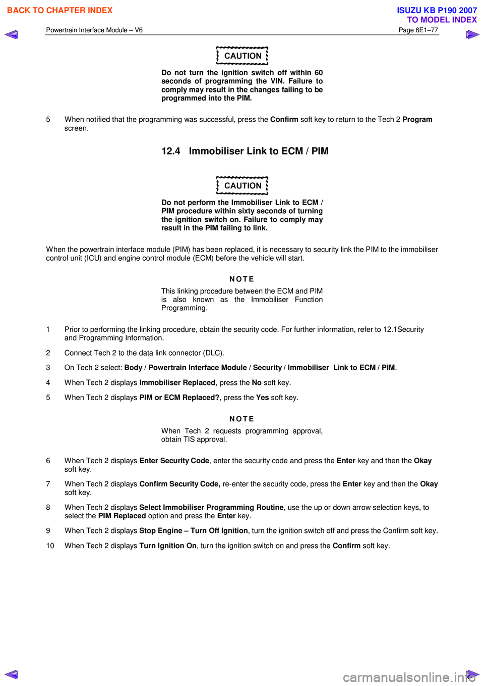
12.4 Immobiliser Link to ECM / PIM
Do not perform the Immobiliser Link to ECM /
PIM procedure within sixty seconds of turning
the ignition switch on. Failure to comply may
result in the PIM failing to link.
W hen the powertrain interface module (PIM) has been replaced, it is necessary to security link the PIM to the immobiliser
control unit (ICU) and engine control module (ECM) before the vehicle will start.
NOTE
This linking procedure between the ECM and PIM
is also known as the Immobiliser Function
Programming.
1 Prior to performing the linking procedure, obtain the security code. For further information, refer to 12.1Security and Programming Information.
2 Connect Tech 2 to the data link connector (DLC).
3 On Tech 2 select: Body / Powertrain Interface Module / Security / Immobiliser Link to ECM / PIM .
4 W hen Tech 2 displays Immobiliser Replaced, press the No soft key.
5 W hen Tech 2 displays PIM or ECM Replaced?, press the Yes soft key.
NOTE
When Tech 2 requests programming approval,
obtain TIS approval.
6 W hen Tech 2 displays Enter Security Code, enter the security code and press the Enter key and then the Okay
soft key.
7 W hen Tech 2 displays Confirm Security Code, re-enter the security code, press the Enter key and then the Okay
soft key.
8 W hen Tech 2 displays Select Immobiliser Programming Routine , use the up or down arrow selection keys, to
select the PIM Replaced option and press the Enter key.
9 W hen Tech 2 displays Stop Engine – Turn Off Ignition , turn the ignition switch off and press the Confirm soft key.
10 W hen Tech 2 displays Turn Ignition On, turn the ignition switch on and press the Confirm soft key.
BACK TO CHAPTER INDEX
TO MODEL INDEX
ISUZU KB P190 2007
Page 3739 of 6020

Powertrain Interface Module – V6 Page 6E1–78
Do not turn the ignition switch off within 60
seconds of performing the ICU Link to
ECM / PIM procedure. Failure to comply may
result in the PIM failing to link with the
ICU / ECM.
11 W hen Tech 2 displays Programming Successful, press the Confirm soft key to return to the Tech 2 Security
screen.
BACK TO CHAPTER INDEX
TO MODEL INDEX
ISUZU KB P190 2007
Page 3740 of 6020

Powertrain Interface Module – V6 Page 6E1–79
13 Powertrain Interface Module –
Tech 2 Functions
13.1 Introduction
Do not use a Tech 2 that displays faulty data;
have the Tech 2 repaired. The use of a faulty
Tech 2 can result in misdiagnosis and the
unnecessary replacement of parts.
From the Main Menu, having selected Diagnostics / 2006 / RA Rodeo / Body , the Tech 2 functions for the Powertrain
Interface, include:
F0: Diagnostic Trouble Codes
F1: Diagnostic Data Display
F2: Snapshot
F3: Miscellaneous Tests
F4: Additional Functions
F5: Program
F6: Security
13.2 Tech 2 Functions
F0: Diagnostic Trouble Codes
W hen this test mode is initiated, DTCs stored by the ECM can be displayed or cleared. W hen entered, there are two
additional modes for selection:
F0: Read DTC Info Ordered By Priority : All DTCs stored in the ECM will be displayed.
F1: Clear DTC Information : Clears all current DTCs in the ECM and TCM memories.
F1: Diagnostic Data Display
• Use the Tech 2 Data List under the following conditions:
• The Diagnostic System Check – V6 Engine has been completed.
• The On-Board Diagnostics are functioning correctly.
• No DTCs are present.
NOTE
The values quoted in the following data list are
only intended to provide the Technician with an
indication of the values to be expected.
BACK TO CHAPTER INDEX
TO MODEL INDEX
ISUZU KB P190 2007
Page 3742 of 6020

Powertrain Interface Module – V6 Page 6E1–81
13.3 Powertrain Interface Module Data List
Diagnostic Data Display
Tech 2 Display Units Displayed Switch On Switch Off
AC Switch On/Off On Off
Cruise Cancel Switch Active/Inactive Active Inactive
Cruise Resume Switch Active/Inactive Active Inactive
Cruise Set Switch Active/Inactive Active Inactive
Cruise Main Switch Active/Inactive Active Inactive
Cruise Control Set Lamp On/Off On Off
Cruise Control On Lamp On/Off On Off
Power Drive Switch On/Off On Off
Power Drive Lamp On/Off On Off
3rd Start Switch On/Off On Off
3rd Start Lamp On/Off On Off
4W D Low Gear Active/Inactive Active Inactive
G-Sensor V 2.43 2.43
G-Sensor Pa 0.027 0.027
Engine Speed RPM 152 1093
Coolant temperature Input °C 35 25
Coolant Temperature % 70 70
Fuel Level Input % 26 26
Fuel Level % 43 43
Alternator Lamp On/Off On Off
Oil Pressure Lamp On/Off On Off
SVS Lamp (Service Vehicle soon) On/Off On Off
Check transmission MIL On/Off On Off
Transmission Oil Temperature Lamp On/Off On Off
LED [ - P - ] On/Off On Off
LED [ - R - ] On/Off On Off
LED [ - N - ] On/Off On Off
LED [ - D - ] On/Off On Off
LED [ - 3 - ] On/Off On Off
LED [ - 2 - ] On/Off On Off
LED [ - 1 - ] On/Off On Off
BACK TO CHAPTER INDEX
TO MODEL INDEX
ISUZU KB P190 2007
Page 3745 of 6020

Powertrain Interface Module – V6 Page 6E1–84
Tech 2 PIM Security Information Data List
The Tech 2 PIM Security Information Data List displays the PIM's current security status.
To view the data list:
1 Connect Tech 2 to the data link connector (DLC) and turn the ignition switch on.
2 On Tech 2 select: Body / Powertrain Interface Module / Security / Security Information .
NOTE
The Tech 2 PIM Security Information Data List
typical display values are obtained from a
correctly operating vehicle under the following
conditions:
• ignition switched on,
• engine not running, and
• vehicle is stationary.
Tech 2 Parameter Units Displayed Typical Display Values
Security Code Programmed Yes / No Yes
Security W ait Time Inactive / Active Inactive
Security W ait Time Inactive / 0:00:00 Inactive
Security Code Reset Counter 0 0
BACK TO CHAPTER INDEX
TO MODEL INDEX
ISUZU KB P190 2007